Almost all classic models are traditionally equipped with a standard contact-type ignition system (KSZ). An exception is 21065, which uses a non-contact transistor circuit in which an interruption of the primary winding power circuit is realized using a breaker mounted in the distributor. Below we will consider in more detail how the contact ignition system of the VAZ-2106 is designed and works.
Contact ignition system device
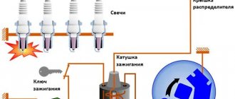
The design of the ignition contact circuit includes the following components:
- lock (switch);
- coil (short circuit);
- breaker (MP);
- distributor (MR);
- regulators, centrifugal and vacuum (CR and VR);
- candles (SZ);
- high-voltage wires (VP).
An ignition coil (IC) with two windings makes it possible to obtain a high current by converting a low voltage.
The mechanical breaker (MP) is structurally made together with a mechanical distributor (MD) in one housing - a distributor. It ensures the opening of the primary winding of the short circuit.
A mechanical distributor (MD) in the form of a rotor with a contact cover distributes current to the spark plugs.
The centrifugal regulator (CR) allows you to change the advance angle (AF) in proportion to the crankshaft speed. Structurally, the CR is made in the form of two weights. During rotation, they act on the movable plate on which the MP cams are located.
The vacuum regulator (VR) makes adjustments to the advance angle (TAA) depending on the load. When the position of the throttle valve (V) changes, the pressure in the cavity behind the V changes. The VR reacts to the degree of vacuum and adjusts the value of the SOP.
Ignition Tuning Guide
Adjusting the VAZ ignition is a priority for many of our compatriots. Before setting the VAZ ignition, you need to check the functionality of the spark plugs and wires. Otherwise, if these elements are not working, you will waste time on adjustments, but you will not achieve the desired result.
So, how to do it right:
- First, unscrew the spark plug and close its hole with your finger or rubber plug. Using a special wrench, rotate the crankshaft until the plug flies out of the hole. If you insert your finger, you will feel the air flow pushing it out.
- The crankshaft must be turned until the mark on its pulley is positioned opposite the mark on the timing cover. After this, you can dismantle the distributor cover. At the same time, make sure that the contact of the timing gear rotor is directed towards cylinder 1.
- Unscrew the nut that secures the distributor and turn it upward. The rotor axis should be set parallel to the axis of the power unit. After this, the nut must be tightened.
- Now, using a control light, connect one of its wires to the coil, namely to its low-voltage contact, and connect the second wire to ground, that is, the car body.
- Turn the key in the lock. The distributor must be turned clockwise until the light goes out. If the lamp is not lit at all, then the system does not need adjustment.
- When the lamp goes out, the breaker should be rotated in the opposite direction. When the lamp lights up again, the device must be fixed in place by tightening the nut.
1. Turn the crankshaft with a wrench.
2. Align the marks on the pulley.
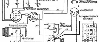
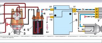
Operating principle and contact system diagram
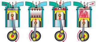
The VAZ-2106 contact ignition system operates according to the following scheme. When the contacts in the breaker close, a low current flows into the primary winding of the short circuit. When the contacts open, a high current is indicated in the secondary winding of the short circuit, which is first transmitted through high-voltage wires to the MR cover and then distributed to the spark plugs.
An increase in crankshaft revolutions leads to an increase in the speed of rotation of the CR, the weights of which diverge to the sides under the influence of centrifugal forces. As a result, the movable plate moves, increasing the SOP. Accordingly, as the speed decreases, the advance angle decreases.
The contact transistor ignition system is a modernized version of the classic circuit, which uses a transistor switch (TC) connected to the circuit of the primary winding of the short circuit. This design solution allows you to significantly increase the service life of the distributor contacts by reducing the current strength of the primary winding.
Types of SZ on VAZ cars
Before checking the VAZ ignition coil, let's understand the types of SZ.
- Contact system. This type is considered one of the oldest; compared to more modern options, it has many disadvantages. As a rule, most often in such systems the circuit breaker and distributor fail. In addition, over time, the SZ contacts may burn and stick, as a result of which the operation of the power unit may be disrupted.
- Contactless ignition on a VAZ or BSZ is a more modern option made by the developers to ensure higher reliability. In this case, the design eliminates the use of a breaker; instead, a contactless sensor is used. Today, BSZ is used on many cars; quite often VAZ owners install it instead of contact SZ. In general, units of this type require virtually no monitoring, since there are no rubbing elements in such systems. The use of BSZ allows you to achieve optimal engine performance and better combustion of the air mixture.
- Electronic ignition is considered one of the most advanced options. Electronic ignition also almost completely eliminates the use of friction components. In addition, such a system is equipped with various controllers, as well as a control unit. Controllers are used so that the electronic ignition can record the operating parameters of the internal combustion engine, and this, in turn, is necessary for the timely supply of a spark. This SZ ensures the most optimal and correct operation of the power unit. But its main advantage is its efficiency (the author of the video is Roman Romanov).
Signs of incorrect ignition on VAZ cars
Setting the ignition timing on a vehicle is necessary if the internal combustion engine is being repaired or the distributor is being dismantled. Also, during operation, it undergoes wear and tear, like any other engine systems, and accordingly the following signs of malfunction may appear:
- The motor does not start or has interruptions in operation. Provided that the combustible mixture is supplied correctly, the malfunction may be an incorrect setting of the advance angle, slipping or stretching of the timing chain.
- Poor acceleration and inelasticity of the engine. This means that the combustible mixture is not ignited at the required piston stroke position, which leads to a deterioration in the efficiency of the internal combustion engine.
- High gas consumption. This effect occurs under conditions of late ignition. Part of the combustible mixture does not have time to burn and flies out into the exhaust manifold. In such cases, you can hear characteristic popping noises in the exhaust while the engine is running.
Hard work of the internal combustion engine. This occurs under conditions of early ignition, when the working mixture ignites when the piston position has not reached top dead center.
In such cases, you can hear a characteristic ringing sound in the engine. Such symptoms can lead to burnt out exhaust valves.
Secondary voltage
Now we need to talk a little about secondary voltage, because it determines how well the air-fuel mixture will ignite. Of course, the breakdown voltage should be high if there is a large gap in the spark plug electrodes. You also need to pay attention to the pressure in the combustion chambers. As a rule, the breakdown voltage fluctuates in the range of 8..12 kV. This is the minimum value at which the air-fuel mixture must ignite.
In order for it to light up for sure, it is necessary to double the voltage. As a result, it turns out that a voltage develops in the secondary circuit in the range of 16..25 kV. The reserve is very large, because during the operation of the car, changes constantly occur. In particular, the spark plug gap may gradually increase as the center electrode begins to burn out. The composition of the air-fuel mixture may also change.
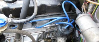
If it turns out to be too lean, then for ignition in the gasoline combustion chambers it is necessary to develop a voltage of at least 20 kV. The photo shows the ignition coils that are used in VAZ cars of the classic series. They can be with three terminals or four. The most reliable are the latter, in which there is one terminal from which the high voltage is removed, as well as three for connection to the low-voltage circuit.
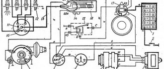
Wiring harness in the cabin
The front wiring harness, located in the engine compartment, is the main electrical system. The front beam enters the car interior through a technological hole with a seal under the instrument panel. The front end electrical system connects to the dash wires, fuse box, switches, and ignition. In this part of the cabin, the main electrical circuits are protected by fuses.
The new cable will provide sufficient voltage to power current consumers in the cabin
The fuse box is located to the left of the steering wheel. Auxiliary relays are attached to the bracket behind the block. The reliable operation of the VAZ 2101 depends on the proper functioning of electrical devices and relays. Fuses protect the electrical circuits of the VAZ 2101 from short circuits.
Simple fuses are a reliable safety element in the event of a short circuit
List of electrical components protected by fuses:
- Horn, brake lights, interior lamps, cigarette lighter, portable lamp socket (16 A).
- Heating motor, wiper relay, windshield washer motor (8 A).
- Main beam of the left headlight, high beam indicator lamp (8 A).
- High beam of the right headlight (8 A).
- Low beam left headlight (8 A).
- Low beam of the right headlight (8 A).
- Side light of the left sidelight, side light of the right rear light, size indicator lamp, instrument panel light, license plate light, trunk light (8 A).
- Side light of the right side light, side light of the left rear light, cigarette lighter lamp, engine compartment light (8 A).
- Coolant temperature sensor, fuel level sensor and reserve indicator lamp, oil pressure lamp, parking brake lamp and brake fluid level indicator, battery charge level lamp, direction indicators and their indicator lamp, reversing lamp, glove compartment lamp ) (8 A).
- Generator (excitation winding), voltage regulator (8 A).
Preparatory work
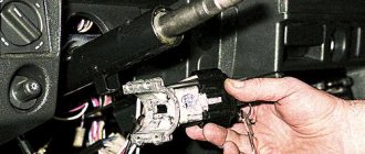
Before proceeding directly to removing the ignition switch, it is necessary to perform a number of actions. First of all, you need to disconnect the negative battery. This way, all electrical systems will be de-energized, and you can safely begin work. After this, it is advisable to remove the covers on the steering column. This is not difficult to do - you just need to have a screwdriver with you and apply a little effort.
After the casing has been dismantled, it is advisable to clean the surface of the lock from various types of contaminants. If you look closely, you can find the wiring harness block. It needs to be disconnected from the contacts of the VAZ ignition switch. All work must be done carefully so as not to damage the wiring. As for the tools, we only need a flat-head and Phillips screwdrivers, as well as a multimeter to check the functionality of the device. Now you can proceed directly to removing the device.