The effective ignition system of the UAZ 469 ensures quick and uninterrupted starting of the car engine under any conditions. With proper ignition, all electrical systems operate without failure: windshield wipers, headlights, receivers, sensors, turn signals. What types of systems are there, adjustment, tuning of the UAZ 469 ignition - in this article.
Ignition system UAZ 469
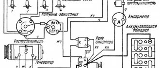
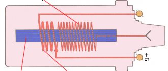
Photo 1: Ignition system of the UAZ 469 car (Source: Yandex.Photos)
Article navigation
Re: Cylinder numbering for UMZ 417
The voltage sensor consists of a rotor and a stator. The second terminal of the winding is electrically connected to the housing in the assembled sensor-distributor. 6. Install the distributor sensor cover, check the correct installation of the ignition wires to the spark plugs in accordance with the operating order of the engine cylinders 1–2–4–3, counting counterclockwise. After each ignition installation, check the accuracy of the ignition timing by listening to the engine while the vehicle is moving.
Numbering from the radiator. Remove the spark plug from the first one, tighten it to compression (check with your finger to see how it hisses), turn it until the moment of ignition (according to the marks on the pulley), and look at the slider. Insert the first wire where the slider is, and the rest are in order according to the direction of the slider.
I apologize for the lame question, but the previous owner of the automobile claims that the numbering of the cylinders in the UMZ 417 does not come from the radiator, but from the passenger compartment. I have encountered this in the French.
And both valves of the first cylinder are closed? Timing gears by marks?
Set the TDC in cylinder 1, remove the distributor from the drive (a boot in common parlance) and look inside. Sometimes the distributor drive is installed incorrectly. Try setting the ignition very early, if it gets better, move the distributor drive gear by 1 tooth. Just carefully reinstall the oil pump drive.
Characteristics of the 417 UAZ engine
Detailed review of the tomahawk tw-9020 car alarm: characteristics, installation, configuration and operating instructions, owner reviews
The basis for the power plant of the UAZ 417 was the 414 engine, which was produced before. In comparison with its predecessor, the unit received a new cylinder head and an increased compression ratio. As for the gas distribution, a new camshaft and intake valves have appeared (the cross-section has become larger). The head of the core received a rounded profile of the outlet channels for the mixture formation mechanism with two chambers.
417 UAZ engine characteristics:
| Explanation | Index |
| Motor purpose | «469», «452» |
| Year of manufacture of the motor | 1989-present |
| Engine fuel | Gasoline (A-76) |
| Motor environmental standards | "Euro-0" |
| How many strokes does the motor have? | «4» |
| Volume 417 UAZ engine (l) | 2,45 |
| Motor block alloy | aluminum |
| Motor positive displacement chamber (pcs.) | «4» |
| Placement of motor chambers | in-line, vertical |
| Motor valve, total (pieces) | «8» |
| The order of operation of cylinders 417 of the UAZ engine | "one/three/four/two" |
| Volumetric displacement chamber, diameter (m) | 0,092 |
| Distance between extreme positions of displacer (m) | 0,092 |
| Squeezing | 7 |
| Motor power (hp) | 92 |
| Pulse turning the crankshaft (Nm) | 172 |
| Motor weight (kg) | 166 |
| Motor service life (km.) | 150000 |
| Motor power | carburetor |
| Gasoline consumption: highway*mixture*city (l/hundred) | 8,4*10,6*14,5 |
| Generator | 3 phase, 75A, 14V |
| Engine ignition | distributor |
| Lubricant application system | pressure + steam |
| Oil volume in 417 engine (l) | 6 |
| Engine oil | 5W-30 (40), 0W-30 (40) |
| Lubricant consumption, (l/1000 km) | 0,6 |
| Liquid cooling | closed, ventilation |
| Coolant, quantity (l.) | 10,7 |
UAZ-469:
The power plant has some features that are not typical for engines of this type, features include:
- Sealing of the sleeves in the frame with rubber rather than copper rings;
- The first motors were produced without stiffeners, later 4 ribs appeared;
- Supply and intake of cooling fluid from the core head;
- Combined exhaust manifold;
- Dome-shaped combustion chamber.
Driving without interference: set the ignition on the UAZ
The operation of a car engine is impossible without correctly set ignition timing. Remove the cover from the ignition distributor. For example, for a VAZ-2106 car, the switch can be installed in the free space between the washer reservoir and the left headlight. Drill 2 holes and screw the switch with self-tapping screws. Correctly setting the ignition timing in a contactless ignition system makes it possible to operate the car in comfortable conditions. Set the crankshaft to a position that corresponds to the ignition timing of 5 degrees. Check the order of connecting the high-voltage wires of the engine cylinders.
The ignition system is fundamental to the normal operation of a car engine. If any actions were incorrect, this will be reflected when the engine is started by the starter and the car is moving. All you need to do is adjust the spark supply - set the ignition correctly on the contactless system. Tighten the bolt at the pointer on the sensor-distributor housing. Be sure to check how the ignition wires are installed to the spark plugs, taking into account the order of operation of the cylinders 1-2-4-3. If there is no detonation, we increase the ignition timing.
Serves to turn on and off the current in the primary circuit of the ignition system and to turn on the starter.
The UAZ distributor is considered one of the important components of the ignition system in a vehicle. What is the connection diagram for electronic or contactless ignition on a UAZ 417, how to convert contact ignition to contactless? Why does the coil heat up and how to adjust and adjust the advance angle? The ignition system can also be electronic. First of all, you must lock your car in one place by pulling the parking brake lever.
The ignition must be installed if the ignition distributor is removed from the engine or if the ignition timing is incorrect. TDC according to the mark on the engine crankshaft pulley (Figure 15.13). The following characteristic malfunctions are possible in the ignition system: the ignition system does not work, the ignition system works intermittently, the ignition timing is incorrect.
This will be the beginning of the compression stroke in the 1st cylinder. 5. Tighten the locking screw and check the gap between the contacts again. 6. Install the rotor and secure the distributor cap.
With the help of an emergency vibrator, the contactless battery ignition system of the UAZ can operate in the event of a failure or breakdown of the transistor switch or stator coil of the sensor-distributor. To switch to working with an emergency vibrator, you must disconnect the wire from the short-circuit terminal of the switch and connect it to the output of the emergency vibrator.
This is visible not only when starting the engine with the starter, but also when the car itself is moving. Afterwards, you need to check the installation of the ignition wires according to the basic order of operation of the cylinders one-two-four-three, counting counter (hours). After you have installed the ignition, you need to check that it is installed correctly while driving.
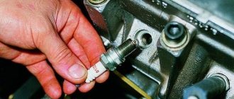
Spark plug gap. What should it be and what does it affect?
Although spark plugs are simple, they must be handled and used correctly. They should be properly cleaned, selected and replaced. However, even new versions can sometimes cause problems - the car may run unevenly, sometimes there are jerks during acceleration, as well as slight detonation. Many people immediately begin to look for the cause in the ignition system - of course, the spark plugs are new! However, the gap between the electrodes may be the culprit, just fix it and the engine will just start singing...
ARTICLE TITLE
First a little definition.
The spark plug gap is the distance between the top and bottom electrodes for optimal performance and ignition of the fuel mixture. If this clearance deviates from the recommended specifications, the engine will run rough and you may experience jerking or knocking similar to your engine.
Simply put, if the gap differs from the norm set by the factory or dealer, then you can even half the engine and still not find the reason. It is especially strong in carburetor systems. But first, I suggest you start with the device and operating principle.
We install and configure the ignition, change the distributor drive on UAZ vehicles
The UAZ distributor is considered one of the important components of the ignition system in a vehicle. Correct adjustment of this mechanism ensures optimal operation of the power unit as a whole. You can learn more about the principle of operation of the ignition system and how to set it up correctly with your own hands from this material.
Review of SZ on famous UAZs
Review of SZ on famous UAZs
What is the connection diagram for electronic or contactless ignition on a UAZ 417, how to convert contact ignition to contactless? Why does the coil heat up and how to adjust and adjust the advance angle? First, let’s look at the main points regarding the action and types of SZ.
Operating principle of SZ
Contact system diagram
The ignition system, or rather its correct setting, plays a big role in the operation and starting of a car engine. With correct adjustment, the combustible mixture will burn correctly in the power unit as a result of the supply of charge through the spark plugs. A spark plug is placed on each cylinder of the UAZ engine, each of which is turned on in a certain order, in turn, delivering a discharge to the cylinder after a certain time. It must be taken into account that any SZ makes it possible not only to deliver the required discharge, but also determines its strength.
Due to its technical characteristics, the car’s battery cannot produce the voltage and current required to ignite the mixture. This is due to the fact that the battery can only produce a current of a certain strength. And thanks to the correct operation of the system, the current value increases significantly, which allows you to successfully ignite the air-fuel mixture.
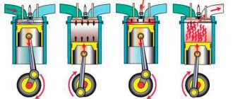
The operating principle of the system consists of several stages:
- First, the driver inserts the key into the ignition and turns it, electrical energy is stored in a coil.
- Then the coil converts the low-voltage voltage in the on-board network of 12 volts into high-voltage. As a result, the voltage value increases to 30 thousand V.
- After this, the discharge is distributed and supplied to one or another spark plug.
- The candle itself produces a spark that ignites the mixture.
Diagram of the UAZ contactless system
What types of SZ are there?
Domestic UAZ vehicles can use one of three ignition systems; let’s look at each of them in detail:
- Contact view. This type of SZ is outdated, however, it is used on most machines. In such a system, the principle of operation is to issue a certain impulse that is formed in a distributor - a distribution device. The contact system is considered one of the simplest in terms of design, which is an advantage, since if a malfunction occurs, the car owner will be able to independently check and repair the system. In addition, prices for structural parts of the contact system are usually affordable, which is good news. The contact SZ includes a coil, a switchgear, a breaker, a capacitor and spark plugs.
- Non-contact type, also called transistor type. Compared to the contact system, the contactless system has more advantages. The resulting spark has a higher power, which is achieved due to the formation of high voltage in the secondary winding of the coil. Also, contactless systems are equipped with an electromagnetic device, which makes it possible to achieve more stable operation of the engine. Ultimately, if the UAZ power unit is configured correctly, then by using a contactless system you can not only increase its power, but also achieve fuel savings, albeit insignificant. Also, such systems are easier to maintain. One of the main nuances in terms of maintenance is the need to periodically lubricate the distributor drive - at least every 10 thousand kilometers. One of the main disadvantages is the difficulty of repair. In practice, repairing a contactless SZ will be problematic, since diagnosing the system will require equipment that is usually available at a service station.
- The ignition system can also be electronic. This option is currently considered one of the most progressive and expensive; it is installed mainly on new cars. Compared with contact and non-contact systems, the electronic system has a more complex structure. The main advantage of this system is that, if necessary, the process of adjusting the ignition angle will be much easier. In addition, there are no contacts in the electronic system that are susceptible to oxidation. It should also be noted that in practice, the combustible mixture in the cylinders of a power unit with an electronic system almost always burns completely. But despite all the advantages, electronic repair systems also have their disadvantages, which relate to device repair. It is almost impossible to repair such an SZ with your own hands, since to perform this task, again, you will need equipment (video published by Nail Poroshin).
Specifications
Detailed review of the Sherkhan Logicar 4 car alarm: characteristics and differences, installation, configuration and operation instructions.
The ZMZ 409 Euro 3 engine has increased technical characteristics compared to its older brother. Thus, the power unit, due to the fact that it was designed on the basis of the 406, received high technical characteristics and endurance. Let's consider the main technical characteristics of the motor:
In addition to the Euro 3 standard, there are a number of modifications that are worth considering:
- ZMZ 409.10 is the main motor, meets the Euro-2 environmental standard. Power 143 hp
- ZMZ 40904.10 - analogue of 409.10 with a new CPG, new gaskets, DBP, complies with the Euro-3 environmental standard. Power 128 hp Installed on Patriot, Hunter, Pickup, Cargo.
- ZMZ 40905.10 - analogue of 40904.10, compliance with the Euro-4 environmental standard. Power 128 hp Installed on Patriot, Hunter, Pickup, Cargo.
- ZMZ 4091.10 - derated low-end version of ZMZ 40904.10, another receiver, camshafts (lift 8, phase 240), firmware, complies with Euro-3 environmental standard. Used on UAZ loaves. Power 112 hp
- ZMZ 40911.10 is an analogue of ZMZ 4091.10, DBP, meets the Euro-4 environmental standard. Used on UAZ loaves. Power 112 hp
- ZMZ 4092.10 is a non-serial motor. Power 160 hp Used on the Volga.
Expert recommendations on how to configure correctly
So, how to set the advance angle yourself in order to achieve proper operation of the UAZ engine:
- First of all, you must lock your car in one place by pulling the parking brake lever. Rotate the crankshaft so that the piston of cylinder 1 reaches TDC (top point). In this case, you need to ensure that the hole on the crankshaft pulley coincides with the mark marked on the timing gear cover.
- After this, remove the cover from the distribution mechanism. After dismantling, you will be able to see the slider, which is located inside the cover itself, opposite the contact. If there is no slider, you should turn the crankshaft 180 degrees again, and then set the octane corrector to 0. Using a wrench, you will need to screw the pointer to the distribution mechanism housing so that it aligns with the middle mark. When these steps are completed, the fastening bolt with which the plates are attached to the distributor body must be loosened slightly.
- Then, holding the slider in one place with a finger to prevent it from rotating, you need to carefully rotate the housing itself, this will allow you to remove possible backlash in the drive. The housing must be rotated until you achieve alignment of the sharp end of the stator mechanism petal with the red mark located on the rotor device. After this, the plate itself must be secured to the body using the appropriate bolt.
- Once you have completed these steps, you need to replace the controller cover and check the high voltage cables. You need to make sure that these wires are installed in the correct sequence, taking into account the firing order of the cylinders. When you manage to correctly adjust the lead angle, you need to make sure that the entire procedure was performed correctly.
- To diagnose the correctness of the actions performed, you need to start the engine of your UAZ and wait about 5-10 minutes until the power unit warms up. The operating temperature of the engine is about 90 degrees; you can wait until the internal combustion engine warms up to 80 degrees. Then you need to drive onto a flat road and accelerate the car to 40 km/h, after which you should sharply press the gas. At this moment, the car will accelerate and if, when the speed increases to 60 km/h, a short-term detonation (metallic knock) is heard from under the hood, then this indicates that all actions were performed correctly. If the detonation is too long, the system will need to be adjusted. To do this, the housing of the distribution mechanism will need to be turned one notch or half, and it must be turned counterclockwise. If the diagnostics showed that there is no knocking of the “fingers” at all, then the advance angle should be increased. To do this, the mechanism should be turned in the opposite direction.
Malfunctions and repairs
Common problems:
- Lack of battery charging occurs when the drive belt slips due to wear or low tension. Repair consists of installing a new part and adjusting the tension. Another reason may be wear on the brush assembly, which needs to be cleaned of dirt and carbon deposits. At the same time, it is recommended to inspect and clean the collector; if there is severe wear, the surface is worn away.
- Constant overcharging of the battery occurs due to a breakdown of the voltage regulator or damage to the power circuit of the integrated unit. The burnt part is replaced with a new one.
- Low generator power occurs when the belt slips or the regulator is damaged. It is also possible that there is an interturn short circuit inside the stator windings, which will have to be replaced. It is recommended to check the functionality of the diode bridge.
- Accelerated wear of the brushes occurs when the commutator beats or the surface of the unit becomes oily. Repair consists of grinding the surface and degreasing it with gasoline.
How to check
Testing the generator is carried out using a test device that is connected to the positive terminal and the housing. The voltage should be in the range of 13.5-14.6 V.
The voltage regulator is tested using a lamp and applying increased voltage. You can thoroughly check the generator in a workshop using a special stand.
Replacing the alternator belt
The type and size of the belt depends on the engine model. For example, the ZMZ-409 injection unit uses a poly-wedge part with a length of 1220 mm. To remove the element, you need to loosen the tensioner pulley and then unscrew the generator mount. After this, the belt is removed from the pulleys and a new part is mounted.
See » How to identify faults and repair the front axle of a UAZ
To replace the V-belt used on carburetor engines, you need to loosen the generator. After installing the new part, tension is ensured by moving the housing along the guide bracket
It is important to align the generator and crankshaft pulleys in the same plane, which prolongs the life of the belt and reduces operating noise
A guide to replacing a distributor with an oil pump drive
Before installing a new distributor with a drive, you need to weigh your strengths, since it is not recommended to make mistakes when performing work.
So, how to replace and install the distributor:
- Turn off the ignition and remove the distributor cover; the tips and high-voltage cables are connected to it.
- Then you need to disconnect the wire connected to the switch from the distribution mechanism. You also need to disconnect the pipe connected to the vacuum regulator.
- Taking a 13mm wrench, unscrew the two nuts securing the device and remove the mechanism along with the oil pump drive from the power unit.
- After completing these steps, you will be able to see the gasket located under the drive. If as a result of these actions the position of the crankshaft has not changed, then simply install a new mechanism, making sure that the slider is located opposite the mark. All actions are performed in reverse order. When the installation is completed, the advance angle is adjusted.
- If, as a result, the location of the shaft has changed, then before installation it is necessary to move the piston of cylinder 1 to top dead center. You need to ensure that the marks on the pulley align with the pointer on the motor itself.
Engine tuning options
Since the UMZ 417 carburetor engine has a heavy piston system, tuning is carried out according to the following scheme:
- boring of exhaust seats up to 39 mm and use of valves from 412 internal combustion engines;
- installation of a 51 mm exhaust pipe;
- Replacing the stock camshaft with a city camshaft to increase torque at low speeds.
Thus, the UMZ 417 motor was copied from the 402 power drive of the Zavolzhsky Motor Plant with minor changes. Even with existing shortcomings, the internal combustion engine serves regularly in UAZ all-wheel drive buses, trucks and SUVs, that is, in very difficult operating conditions.
We carry out the wiring diagram for electronic ignition on a UAZ
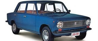
Classics of the domestic auto industry
Many UAZ vehicles are equipped with a contactless ignition system. It makes it possible to save fuel, reduces the amount of harmful substances in gases, and makes it much easier to start the car in winter.
The connection diagram for electronic ignition on a UAZ is not as complicated as it might seem at first glance. A person who has at least a little knowledge of technology will be able to repair and correct problems himself, if any arise.
Ignition system on UAZ 469
The ignition system for the UAZ 469 can be made not only at a service station, but also with your own hands. It consists of:
- ignition coils or distributor;
- switch;
- emergency vibrator;
- variator (additional resistor);
- spark plugs.
Today, contactless ignition systems are most often preferred. The most interesting thing about them is the switch.
If the crankshaft rotates at a frequency of 500 revolutions per minute, it turns out that the signal at the sensor output will change too quickly. This mode is used if you start the engine with the starter. At this time, there will be not just one spark on the candles, but many, which will make it possible to start the car easily and quickly. Ignitions on UAZ have a simple design.
Contactless ignition is more convenient to use than contact ignition.
Installation instructions
Installing contactless ignition on the UAZ 469 is quite easy. It is easy to configure and install, and the reliability of the UAZ ignition can only please us. It works very accurately, even in the cold season, when starting the car is quite difficult.
Once a new system has been purchased, it must be installed. To install you will need:
- drill;
- self-tapping screws;
- drill;
- key to 38;
- open-end wrench 13;
- Socket and socket wrenches for 10 and 8.
Ignition on the UAZ 469 is done as follows:
- First, the engine must be set to the TDC mark using a 38 key. Before you do anything with the equipment, you need to remember the location of the parts before replacement.
- We look at how the slider and distributor are installed, so that we can then install a new one in the same position. Next, we find the place where the ignition coil is located, on which we find the B + mark and look at the location of the wires and what is attached to what. After everyone has looked, you can unscrew the coil. We remove the distribution lock, place the switch, and also install the ignition coil and attach it to the body. We connect standard wires. From the switch, wires labeled + are attached to terminal B, and a second wire is attached to terminal K.
- You connect the distributor, but the nut is not tightened completely. You need to connect the wires from the switch to it. After this, you need to check the location of the slider and distributor, put on the cover and connect all the wires in the order in which they were before replacement.
- When everything has already been replaced and secured, you should start the engine, check how it works, and adjust any inaccuracies.
Adjusting the ignition of a UAZ is a fairly simple task. With the engine running, you need to turn the distributor very slowly to find the position at which the engine will run smoothly and the speed will be high.
The UAZ 469 car has an ignition coil, which is also a kind of transformer that converts low voltage to high voltage. When the engine is running, current flows through an additional resistor into the primary winding of the ignition coil. It is located between the legs of the fastening brackets - in the insulator.
When the engine is started using the starter, the resistor is turned off, and the current flows into the primary winding without entering it, which makes starting the engine much easier due to the enhanced spark.
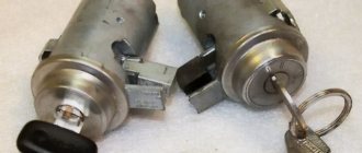
How to connect the ignition switch
Replacing the ignition switch involves dismantling the old one and installing a new mechanism with its subsequent connection. To remove the old lock you will need a Phillips and flathead screwdriver.
The procedure for dismantling the old vehicle ignition system lock:
- Remove the fasteners from the lower trim panel of the steering column.
- Insert the key into the lock and set it to the zero position, at which the steering mechanism will be locked.
- Remove the steering column.
- Unscrew the ignition switch mounting bolts.
- Insert a flat-head screwdriver into the small technological hole and press the latch that holds the lock.
- Push the lock out of its seat.
- Disconnect all system wires.
- Install a new lock, connect the wires and reassemble the mechanism, performing all the steps in reverse order.
All wires are connected in a clockwise direction.
To terminal number 50 you need to connect a red wire, which is responsible for the stable operation of the starter device.
To terminal number 15 you must connect a blue wire with a black stripe, which is responsible for heating the vehicle interior.
A pink wire is connected to pin number 30, and a brown wire is connected to 30/1.
The black wire must be connected to the INT connector, which is responsible for the operation of the side lights and headlights.
After all the wires are connected, you need to connect the battery terminal. A black wire should be connected to the top of the terminal. Then you need to start the engine and check the serviceability and functionality of the entire ignition system. First, it is recommended to check the operation of electrical devices, and then the serviceability of the starter mechanism.
If all wires are connected correctly, then when the ignition system key is in the zero position, all elements of electrical equipment will be disconnected from power. When the key is turned to the first position, the system is activated, which controls the internal combustion engine, generator set, headlights and brake lights, as well as washers and windshield wipers. When the key is moved to the second position, the starter is activated, the anti-theft system rod extends and retracts when the key position is changed.
If this does not happen, it means the wires are connected incorrectly. It is necessary to disassemble the mechanism and repeat the connection procedure.
Coil device
Underwater ignition on a jeep
The UAZ 469 ignition coil has a complex design:
- screw-in terminal with high voltage;
- voltage output;
- lid;
- contact spring;
- low voltage clamp;
- gasket for sealing;
- fastening bracket;
- magnetic circuits;
- contact plate;
- primary and secondary winding;
- insulation gaskets;
- frame;
- insulator;
- iron core;
- insulating mass;
- additional resistor and its insulator;
- screw and plate for fastening the resistor.
What characteristics does the generator have?
The factory UAZ is a fairly low-power vehicle. On earlier releases, the output current of its generator was only 40A. Then the parameter increased to 60A. The design of the rectifier unit and voltage regulator has changed. What kind of standard generator did the UAZ “Bukhanka” have? Model 452 is a very unreliable unit. Fortunately, you can easily find out about its problems using the ammeter built into the dashboard. Another feature of the old generator is the voltage regulator, made in the form of a separate unit. If it malfunctioned, due to self-excitation of the winding, the engine refused to stall when the ignition was turned off.
New generators have a different design and, accordingly, a different connection diagram. Here the voltage regulator is built into the brush holder and is made as a single unit. The differences also apply to the drive belt. Old devices were driven by a narrow belt, new ones by a wider, poly-V belt. The UAZ Patriot generator is more powerful, with an output current of up to 120A, since this vehicle has many electrical consumers installed, which is not present in previous models.
UAZ 31514 wiring diagram for ignition conversion
Many UAZ owners know about the vagaries of classic ignition, which sometimes presents unpleasant moments. And often craftsmen find ways to modernize a problematic unit or an entire system. And one such method of improving the launch system with your own hands will be discussed in this publication.
In the photo, UAZ 31514 is a reliable all-terrain vehicle for many purposes.
General concept
The contact ignition circuit itself is not bad, because humanity has been using it since the advent of the first car. But, of course, it is far from the capabilities of contactless ignition. Therefore, many UAZ owners, in an effort to improve the performance of the power unit, reconfigure it.
General ignition circuit for older UAZ models
And not only UAZs, but also other domestic cars, for example, the wiring of the Moskvich 2141 and a number of other brands and models are subject to alterations.
Effect of modernization
What is important is that the engine compartment and interior electrical wiring of the UAZ 31514 remains virtually unchanged, and the alteration itself is characterized by the installation of new elements under the hood.
As a result:
- The engine begins to operate stably in all modes;
- Improves cold starting;
- Fuel consumption is normalized;
- The engine power will reach the passport data.
Differences between ignition systems
The main difference between the two systems is the moment of sparking:
- In classic ignition, a slider under the distributor cover is responsible for this when it comes into contact with the output contact on the spark plug wire. In this case, the supply of a high-voltage pulse occurs with an increase. It seems to be lubricated, reducing the spark power at the spark plug electrodes.
- In contactless ignition, the switch generates a charge and releases it almost instantly upon receiving a signal from the Hall sensor. As a result, the candle produces a more powerful spark. Among domestic off-road vehicles, the Niva has a similar contactless ignition system - see the VAZ 21213 wiring diagram.
The electronic switch is often mounted in UAZ vehicles on the partition on the left side.
Please note! More powerful sparking promotes self-cleaning of the spark plug, because The fuel burns intensively, leaving no deposits.
Period from 1965 to 1984
hi-electric.com Hall sensor: how to connect, check or replace, where it is located, principle of operation, signs of malfunction, linear or analog, dual-circuit ignition. Electronic ignition with hall sensor During this period, the automaker equipped its products with electrical components available to the domestic industry. Some of them were known for a long time, others were experimental, as evidenced by videos from previous years, and which had to prove their suitability.
Connection diagram for headlights on UAZ 452 first editions
Lighting control
In particular, the controls and a number of main units migrated from its predecessor, the GAZ-69. Thanks to this, the price of the car remained the same.
On models of the first years of production, a foot light switch was installed, which had several operating modes:
- The first position activated the circuit for switching the low beam headlights and side lights;
- In the second position, the low and high beam headlight circuit was activated.
Foot switch for headlights and parking lights
The modernized light switch has a different operating algorithm:
- The first position supplies power to the side lights only;
- The second position is side lights and low (high) beam headlights.
The most correct option is to replace the old switch with a modern one, which uses only 3 contact groups.
Also, on older versions of the “452” there was no alarm, so in the electrical diagram:
- An RS-57 breaker relay was installed (mounted in the wiring gap from the “+” terminal of the battery to the direction indicator switch);
- The middle contact of the relay closed the indicator light on the instrument panel.
Ignition system
Ignition of UAZ 452 model 1968
Also on the “452” contact ignition was installed:
- The “+” wire from the battery supplied power to the ignition coil;
- From the coil, the high-voltage wire transmitted the impulse to the breaker (distributor) and further to the spark plugs.
Period from 1985 to 2013
In later modifications, with the advent of injection, some changes were made to the ignition:
- An additional resistance was installed in the “battery-ignition coil” circuit;
- A separate wire from the starter was laid to the coil wire connection terminal (past the additional resistance)
- On later models, an additional starter relay was installed in the circuit.
Control devices UAZ 452
Conclusions: along with the car, the electrical circuit also changed. This factor should be taken into account when carrying out scheduled repair work in order to eliminate emergency situations.
What to buy
In fact, you don’t need to buy much, and if you have a working distributor and reel, then the list of purchases will be minimal.
So, you need to buy:
- Hall Sensor;
- High-voltage wires (preferably silicone);
- Switch from VAZ 08.
Advice: If your UAZ is already many years old, then we recommend that in addition to the already indicated list, you buy a new distributor, a coil, and you will also need UAZ 31514 wiring with connectors for the switch.
For reconfiguration and operation, you will also need a new UAZ 31514 wiring diagram, which is shown in the photo below, and which you can print for convenience.
For a new ignition - a new circuit
You can also make your ignition system more powerful by upgrading it with two kits at once:
- Two switches;
- Two Hall sensors;
- Two ignition coils.
With this approach, each subsystem will be responsible for sparking 2 cylinders at once:
- First and third;
- Second and fourth.
Most often, UAZ cars that take part in competitions or are used by professional fishermen and hunters are subjected to such serious modifications. The video below shows how an engine works with such a system.
Advice: if you use your UAZ 31514 in everyday life, not related to extreme sports, then it is enough to limit yourself to alterations with one set - it’s easier to maintain it. After all, domestic all-terrain vehicles use a proven UAZ wiring diagram.
Site about off-road vehicles, SUVs, off-road vehicles
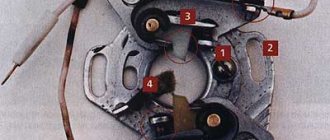
The procedure for installing the ignition on a UAZ-469B car is as follows. Remove the distributor cap and rotor and check the gap between the breaker contacts. If it goes beyond the range of 0.35-0.45 mm, it is necessary to adjust the gap and put the rotor in place.
Unscrew the spark plug of the first cylinder and, covering the hole for the spark plug with your finger, turn the engine crankshaft with the starting handle until air begins to escape from under the finger. This will occur at the beginning of the compression stroke in the first cylinder.
After making sure that compression has begun, carefully rotate the engine crankshaft until the hole on the pulley aligns with the pin. Then use the nuts to smoothly adjust the octane corrector scale to zero division.
Loosen the screw securing the breaker housing and turn the distributor housing counterclockwise enough to close the breaker contacts.
Take a portable lamp and, using additional wires, connect one of its wires to the body, the other to the low voltage terminal on the coil, to which the wire going to the distributor is attached.
Turn on the ignition and turn the distributor housing clockwise until the light comes on. The rotation of the distributor should stop exactly at the moment the light comes on. If this fails, repeat the operation.
Secure the distributor housing with a screw, put the cover and central wire in place.
After each installation of the ignition and after adjusting the gap in the chopper, it is necessary to check the accuracy of setting the ignition timing of the combustible mixture by listening to the operation of the engine while the car is moving. The ignition installation can be fine-tuned using an octane corrector without loosening the mounting screw. To do this, just rotate the smooth adjustment nuts, unscrewing one and tightening the other.
The most advantageous ignition timing will be one in which during sharp acceleration, full throttle opening, a fully loaded vehicle on a horizontal road with an initial speed of 30-35 km/h in direct gear, single detonation knocks in the engine cylinders can barely be heard.
If there are no knocks during intensive acceleration of the car, this means that the ignition is late. Conversely, the appearance of a series of successive distinct knocks indicates too early ignition.
Maintenance of ignition coil B7-A.
After one maintenance, you should check the condition of the coil directly on the car using a special portable device. The ignition coil is considered to be in good condition if, with a spark gap of 7 mm, uninterrupted and intense sparking is observed.
In the absence of a special device, the ignition coil can be checked on a specialized bench by comparing it with the standard coil of the bench along the length of the spark on an adjustable spark gap. If the spark length of the coil being tested is 2 mm shorter than the spark length of the reference coil, the coil being tested must be replaced.
Maintenance of the ignition distributor-distributor P119.
When carrying out maintenance, it is necessary to check the reliability of the electrical connections and fastening of the breaker-distributor to the engine and lubricate the distributor. Lubricate the distributor shaft by turning the oiler cap one turn.
Place one drop of engine oil on the axis of the breaker lever, one or two drops on the cam brush and three or four drops on the cam bushing, after removing the rotor and the felt underneath. When lubricating the cam and the breaker axis, you must ensure that the oil does not get on the breaker contacts.
After one maintenance, inspect the distributor contacts, remove dirt and oil from the contacts, wiping them with a rag lightly moistened with gasoline. Then wipe them with a clean, dry cloth that does not leave lint on the contacts. Burnt or oxidized contacts must be thoroughly cleaned.
After cleaning, wipe the contacts with a rag slightly moistened with gasoline and check the gap between them with a feeler gauge. If the gap differs by more than 0.05 mm from the nominal 0.35-0.45 mm, then adjust it. However, the specified gap between the contacts ensures normal operation of the ignition system only with new contacts. More reliable is to adjust the gap in the contacts of the breaker by changing the angle of the closed state of the contacts.
Rework
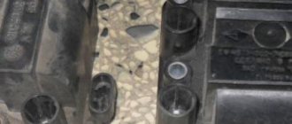
Actually, the work itself comes down to remaking the distributor, which will no longer have a high-voltage part - an electronic switch will generate high-voltage pulses for it . The photos below show the location of two sensors at once.
The sensors are attached to the base and the contact plate has curved edges
Pay attention to the shape of the contact plate:
- It has curved ends - the sensors are located vertically;
- Flat – the sensors are mounted horizontally.
Flat plate option
Flat plate option
Both options are working, it all depends on the design of the distributor. In the future, you only have to adjust the ignition. The instructions are simple - you must remember that sparking begins when the edge of the plate is in the center of the Hall sensor.
The order is as follows:
- Rotate the crankshaft until the piston in the first cylinder reaches TDC;
- Rotate the distributor body until the contact plate is in the sensor slot;
- Carefully tighten all mounting screws to eliminate any play.
- Start the engine.