The lubrication system of a car engine or the engine lubrication system (ELS) is a set of car mechanisms that are involved in reducing friction between the mating parts of the internal combustion engine, minimizing the power consumption of the internal combustion engine on friction. The operating principle of the engine lubrication system is to ensure the supply of lubricants (engine oil) to all rubbing parts of the internal combustion engine in all operating modes. The SSD works cyclically. An oil film forms between two surfaces of moving bodies. It separates moving surfaces and protects rubbing surfaces from additional loads.
Purpose of the lubrication system and functions performed
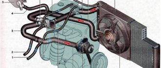
Engine lubrication system
The internal combustion engine of any vehicle consists of many elements that interact very aggressively with each other during its operation. Due to their constant movement inside the installation, a high friction force arises, leading to large power losses and, as a consequence, increased fuel consumption. Prolonged operation “dry” can even lead to jamming of the power unit: increased interaction of parts will lead to heating of their surfaces and further expansion; as a result, this will reduce the working gaps of the structure and will lead to their filling with metal shavings formed as a result of the destruction of the main elements.
To prevent this condition and extend its useful life, the internal combustion engine is equipped with a lubrication structure that facilitates the movement of parts, creating a strong protective film around the elements of the internal combustion system.
Thus, the lubrication system of any two-stroke or four-stroke engine performs the following number of functions:
- Reducing the friction force between working elements;
- Cooling their surfaces;
- Reduced engine operating temperature;
- Removal of metal shavings and contaminants outside the working space of the installation;
- Prevention of rapid wear, destruction and coking of parts;
- Ensuring the required working fluid pressure for efficient operation of the internal combustion engine (changing the timing of the gas distribution mechanism, adjusting the operating valve clearances with hydraulic compensators).
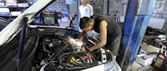
MAIN FAULTS
The design of the oil pump, no matter what type it is, is relatively simple, which ensures its reliability and long service life. And yet it does have faults, or rather there is only one – a decrease in productivity, which leads to a drop in pressure in the system. And this can lead to more serious damage, since components that are not sufficiently lubricated begin to wear out intensively due to oil starvation. This can happen for various reasons.
- The first of these does not apply to the pump, but leads to negative consequences in its operation - clogging of the oil receiver mesh with wear products and dirt. As a result, insufficient oil flows to the pump. It is not difficult to fix such a malfunction - just remove the pan and oil receiver, then thoroughly clean and rinse the mesh.
- The problem with pressure drop can occur due to wear of the pump components or prolonged operation with oil that contains a large number of contaminants. The result of this is the formation and increase of gaps between pump parts. Because of this, the lubricant simply flows through these gaps inside the injection cavity and the gears or rotors are not able to capture it in order to pump it into the line. In most cases, the performance of the lubrication system is restored by replacing worn elements or the assembly as a whole.
- The bypass valve can also create problems. Due to dirt, it can jam in the open position, and oil will constantly flow into the pan. This malfunction can be eliminated by disassembling and washing the pump and its channels.
Lubrication system design
We figured out what this system is intended for, now it’s time to study its structure. Each car has its own lubrication system, so its design components may differ significantly from each other. It may be supplemented with some elements, or it may not have the following components at all, but, as a rule, modern systems are characterized by the presence of the following elements:
- Carter with pallet. The sump is the lowest part of the power plant. It is attached to the crankcase using bolts and gaskets and serves as a kind of “storage” for the working fluid. In the sump, it cools and “calms down” - thanks to special partitions, the engine oil stops agitating when the vehicle moves over uneven surfaces.
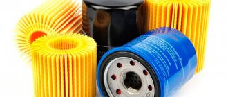
- Filter. The filter element in the lubrication system serves as a place where the working fluid “brings” debris that impairs the performance of the power plant. This can be soot, soot, dust from outside, metal shavings and other pollutants. Once the filter is clogged, the engine oil begins to quickly lose its properties due to an excessive amount of dirt particles, which leads to a loss of power performance of the entire vehicle. In order to prevent harmful consequences for the internal combustion engine, it is necessary to promptly replace the working fluid and do not forget to change the filter elements.
Oil filter
- Oil pump. Without a pump, the operation of the mechanism would not be possible: it is the pump that creates the required pressure inside the installation and “forces” the working fluid to act on the mechanisms. There are two types of pumps used in cars - gear and rotary. The first type of units provides oil supply with constant pressure, while the rotary unit allows for changing the supply force. A pressure of 2 to 16 atmospheres is created inside the engine compartment.
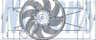
- Radiator. This element of the engine lubrication system ensures cooling of the engine oil. Moreover, cooling can be of two types - liquid and air.
- Reducing and bypass valves. These elements allow you to reduce blood pressure if it exceeds the established norm. These elements are installed inside the power plant next to the oil pump, filter, etc. and are activated by the activation of special sensors. For example, when the filter is clogged, the bypass valve allows working fluid to bypass it to prevent the entire engine from stopping.
- Oil pressure and temperature sensors. It is thanks to them that the on-board computer learns about the performance of the system. The pressure sensor is installed in the central line and measures the main parameter. If it deviates from the norm, an indicator lights up on the car’s dashboard.
- Lubrication channels. It is not difficult to guess what these elements are used for: they provide the supply of motor fluid to interacting mechanisms.
- Main highway. Carries out the flow of oil from the pump to the filter. Thanks to the large cross-section, the line maintains fluid circulation at the required level. Also, thanks to the line, the crankshaft bearings are lubricated.
Depending on the design features of the vehicle, a modern lubrication unit can be supplemented with other components.
Valve N428
The oil pump control valve N428 is designed to regulate the pressure on the control piston. Depending on the pressure on the piston, the position of the stator and the volume of the suction chamber changes. Part of the oil from the discharge cavity is always supplied to the control line to valve N428. At the command of the engine control unit, power is supplied to the valve and oil is supplied to the control piston. By design, the N428 is an electrically controlled hydraulic 3/2 way valve.
Types of lubrication systems
Despite the fact that all devices in the lubrication system perform the same functions, it can be of three types:
- oil spray system,
- pressure fluid supply system,
- combined system.
The first type has a fairly simple device: here the oil gets to the working parts thanks to special scoops installed on the crank heads of the connecting rods. The liquid captured from the pan is dispersed throughout the working area in the form of oil mist.
The disadvantage of this method of oil distribution is associated with uneven lubrication of structural elements due to periodic changes in its level in the lower engine container - the sump.
The volume of working fluid constantly changes with increasing crankshaft speed, tilting the vehicle and in aggressive driving mode. The scoops cannot control the amount of liquid splashing, so the motor periodically begins to experience oil starvation or, conversely, choke from an excessive amount of liquid.
The second type of system involves a continuous supply of engine oil to all elements of the installation. The lubricant composition is collected in the installation crankcase, and then supplied through special channels to the working unit. After completing the set goals, the oil flows into the oil pan. If in the first type of system it is not possible to adjust the amount of oil, then in the second type such adjustment is quite possible. Despite the fact that the system provides an economical and rational distribution of technical fluid, it has not received widespread use - it involves too costly and labor-intensive production.
Engine oil in the engine
By combining the technologies of spraying and supplying oil under pressure, engineers were able to create a combined type of lubricant distribution: protective fluid is supplied to the main structural components that are most susceptible to wear under pressure, while the rest of the mechanisms, operated in quieter conditions, are sprayed with oil by splashing.
The combined system involves the use of a wet and dry sump. A wet sump means that it is constantly filled with working fluid. The simplicity and reliability of the principle allowed it to become widespread: almost all standard cars are equipped with a similar system. However, it has some not entirely pleasant drawbacks: if air or a fuel mixture gets into the crankcase, the oil composition begins to foam and lose its lubricating properties. As a result, the internal combustion engine remains without the proper level of protection. To prevent such an unfavorable effect, diagnostics of the vehicle system for depressurization should be carried out regularly.
A dry sump is ensured by the presence of a special tank in the power plant, into which all waste fluid flows. Here, mixing it with air and the fuel mixture is simply impossible. The advantages of such a system include the stability of its operation when the vehicle passes obstacles with a large angle of inclination. The dry sump principle is used on racing cars, sports cars and some SUVs.
Choosing engine oil
The main task of motor oil is to prevent dry friction of the moving internal parts of the engine, as well as to ensure minimal friction force with maximum tightness of the working cylinders.
Based on the requirements of the engine of a particular car and the ambient temperature, motor oil is selected according to two main criteria: - the level of performance properties according to the API or ACEA classification, which must meet the requirements of your engine; — viscosity according to SAE classification, which is selected depending on the ambient temperature and the degree of engine wear.
One of the main properties of motor oil is its viscosity and its dependence on temperature over a wide range (from the ambient air temperature at the time of cold start in winter to the maximum temperature in the engine at maximum load in summer). The most complete description of the compliance of the viscosity-temperature properties of oils with engine requirements is contained in the internationally accepted classification SAE3000.
Operating principle of the lubrication structure
Lubrication system operation
The principle of operation of the lubrication system is the uninterrupted supply of working fluid to all elements subject to mechanical wear.
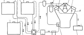
The operation diagram of the lubrication system is as follows. During startup of the power plant, the oil receiver captures the required amount of oil from the oil pan and directs it to the oil pump. The pump, in turn, sets the fluid force and speed with which it will circulate cyclically through the system. After the pump, the oil enters the filter and undergoes thorough cleaning. As mentioned earlier, if this element of the chain is dirty, the bypass valve will allow the working lubricant to bypass the filter element. After it, the fuel and lubricants are sent to the bearings of the connecting rods and crankshaft, the camshaft supports and pins, and the rocker arms of the valve drive. If there is a turbocharger, oil is also distributed onto its shaft.
The working mixture enters the inner sides of the cylinders through holes in the connecting rod head. Here it ensures unhindered movement of oil scraper and compressor rings and reduces wear on the cylinder walls. After lubricating the elements of the power plant, the waste liquid is returned back to the car sump, where, under the influence of a continuously rotating crank mechanism, it is sprayed over the remaining elements of the system.
Oil filter
The filter is full-flow, non-separable, screwed onto the fitting of the cylinder block and connected by channels to the oil pump and the main oil line. To remove the filter, use device A.60312. When installing the filter, it is recommended to wrap it manually without a tool. A filter element made of special cardboard is installed in the steel filter housing. The filter has anti-drainage and bypass valves. The anti-drainage valve does not allow oil to drain from the system when the engine is stopped, the bypass valve allows oil to pass through when the filter element is clogged from the pump into the main oil line.
Possible problems with the system and how to resolve them
Some engine problems in the lubrication system may occur unexpectedly, even if you recently repaired the car or carried out its maintenance. Let's list the main problems and look at ways to solve them:
| Type of malfunction | Cause | Elimination |
| The oil pressure sensor does not light up when the ignition is turned on. | 1. The indicator is burnt out | 1. Replace the gauge bulb in the dashboard |
| 2. Damage to the wire, oxidation of the connector | 2. Inspect the connection and, if necessary, replace the wire | |
| 3. Failure of the oil pressure sensor | 3. Replace the sensor with a new one | |
| The oil pressure indicator lights up at idle and turns off when the speed increases. | Low oil pressure due to overheating. The cooling system is not working properly | “Drive” the car at high speeds for 15-20 minutes to cool the engine; Carry out a diagnostic inspection of the cooling system performance |
| The indicator on the dashboard lights up at increased engine speeds | Reducing valve faulty | Using a dipstick, check the engine oil level in the car and, if necessary, replace the pressure relief valve |
| The indicator is constantly on | 1. Too low amount of oil fluid | 1. Check the oil level and add if necessary |
| 2. The pump does not work, the oil pump channel is dirty | 2. Clean or replace the pump | |
| High oil consumption | Wear of cylinders, piston rings, valve stem seals, sealing elements | Inspect the engine system and eliminate the cause of the leak. |
Main oil line
The main oil line runs in the middle part of the block. From it, oil flows through inclined channels to the main bearings and camshaft bushings. There are grooves on the second and fourth journals of the camshaft. When each of these grooves coincides on one side with the hole through which oil is supplied to the bearing, and on the other with a channel in the block, the oil passes into this channel and then enters the corresponding cylinder head to lubricate the parts of the gas distribution mechanism located in them. The resulting pulsating supply of oil is quite sufficient to lubricate the rocker arms and the upper ends of the rods.
From the main oil line 4, which is a channel in the crankcase boss, oil is supplied through channels to the main bearings, and then through channels in the crankshaft to the connecting rod bearings. From the main bearings, oil also flows through channels in the walls of the crankcase to the camshaft bearings.
From the main oil line, oil under pressure through the holes in the crankcase and block flows to the main bearings 13 of the crankshaft, the camshaft bearings 14 and the hollow axis 15 of the rocker arms. From the main bearings, through holes in the journals and cheeks, oil is supplied to the connecting rod bearings of the crankshaft.
From the main oil line there are inclined channels 21 to all five main bearings.
| Diagram of the ZMZ-53 engine lubrication system. |
From the main oil line, oil under pressure is supplied to the crankshaft main bearings, camshaft bearings and rocker arm axles. Oil is supplied to the connecting rod bearings through channels in the crankshaft cheeks and the cavity of 11 dirt traps made inside the connecting rod journals. In these cavities, the oil is cleared of mechanical impurities, which, under the influence of centrifugal forces, are thrown to the walls of the cavities and settle on them. Other parts of the crank mechanism and the gas distribution mechanism are splash lubricated.
From the main oil line, oil under pressure through holes in the crankcase and block flows to the main bearings 13 of the crankshaft, bearings 14 of the camshaft and into the hollow axis 75 of the rocker arms.
| Diagram of the MAI engine lubrication system. |
From the main oil line, oil flows through inclined channels 4 to the main bearings of the crankshaft, and from there through the shaft channels to the connecting rod bearings. Through channels 5, oil from the main bearings flows to the four camshaft bearings. The oil coming out of the connecting rod bearings and spraying lubricates the cylinder walls. From the front and rear camshaft bearings, oil flows through pipelines 2 and channels in the cylinder heads and rocker arm axle supports to the rocker arm axles and rocker arms.
From the main oil line, oil is supplied through the power regulator Z through channel 6 to the manual control spool L, through channel 12 to the 1st-2nd gear shift valve E and through channel 9 to the 2nd-3rd gear shift valve B. Oil pressure in channel 12 (throttle pressure) depends on the movement of the gas pedal.
Inside the crankcase there is a main oil line with branches to lubrication points.
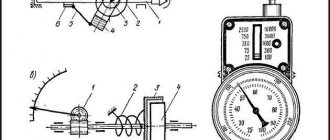
The pressure gauge is connected to the main oil line 4, and the thermometer sensor is installed in the cavity of the slotted oil filter.
| A. Lubrication chart for tractors type DT-54. D-54 engine lubrication diagram. |
ASFO-I: / - main engine oil line, 2 - drive gear of the oil pump, 3 - oil pump housing, 4 - oil pan, 5 - oil receiver screen, 6 - driven gear of the oil pump, 7 - drain plug , 8 - oil gauge line, 9 - oil pump pressure reducing valve, 10 - oil pump discharge channel, II - drain valve, 12 - thermostat valve, 13 - oil line from the pump to the filter housing, 14 - safety valve, IS - oil lines from filter housings to the oil cooler, 16 - filter housing, 17 - remote thermometer sensor, 18 - internal element of the coarse filter, 19 - external element of the coarse filter, 20 - cardboard element (ASFO-1) of the fine filter, 21 - calibrated hole in the wall of the coupling bolt, 22 — oil filler neck, 23 — remote thermometer indicator, 24 — pressure gauge, 25 — oil radiator.
Some of the oil from the main oil line is supplied through an oil pipeline to a fine oil filter 13, which retains small particles of mechanical impurities. After passing through the fine oil filter, the oil returns through the oil line through the oil filler neck 12 to the oil pan.
Main oil line
Below the water jacket, along the right wall of the crankcase, there is the main oil line 11 (Fig. There are channels in the walls and bosses of the block to supply lubricant to the rubbing parts.
The upper section of the pump supplies oil through channels in the block to the main oil line, from where it passes to all rubbing surfaces. Unlike the ZIL-130 engine, the GAZ-53 engine oil from the lower section does not flow into the oil cooler, but into a centrifugal filter. Thus, the filter is connected in parallel and part of the oil passes through it, drained into the crankcase after cleaning.
| Diagram of a serial jet oil centrifuge KhTZ, connected to a branch of the main oil line and operating with a coarse filter. |
The RMC jet oil centrifuge of the D-54 tractor engine is connected to a branch of the main oil line.
The filter has a bypass valve that ensures oil flow into the main oil line, bypassing the filter, in case of significant contamination of the filter element, as well as in case of high oil viscosity during engine starting and warming up.
| Schematic diagram of the lubrication system. |
Oil pressure is controlled by electric pressure gauge 11, the sensor of which is installed in the main oil line, and the indicator is on the instrument panel. On some engines, to monitor the oil temperature, there is an electric thermometer 2, the sensor of which is mounted in the crankcase pan.
The connecting rod bearings and piston pin of compressor 6 receive lubricant from the main oil line 8 of the engine through a tube through the rear cover, seal and channels of the crankshaft and connecting rod of the compressor. After lubricating the compressor parts, the oil is drained into the engine crankcase through the chute of the compressor mounting bracket.
Oil pressure is controlled by electric pressure gauge 11, the sensor of which is installed in the main oil line, and the indicator is on the instrument panel. On some engines, to monitor the oil temperature, there is an electric thermometer 2, the sensor of which is mounted in the crankcase pan.
| Gear oil pump diagram. |
Oil pressure is controlled by electric pressure gauge 11, the sensor of which is installed in the main oil line, and the indicator is on the driver’s instrument panel. On some engines, an electric thermometer 2 is used to monitor the oil temperature, the sensor of which is located in the crankcase pan. Gear pumps are used in the lubrication system of automobile engines. The pump housing 5 (Fig. 12) contains the drive 7 and driven 2 gears. When the gears rotate, oil enters the suction cavity 6, fills the cavities between the teeth and is transferred in the cavities along the walls of the housing into the discharge cavity. Drive gear 7 is steel, mounted on a shaft, which is usually driven from the camshaft. Driven gear 2 rotates freely on the axle.
When centrally filling machines and mechanisms with lubricating oil, the valve pipe is connected to the main oil line.
The pressure in the lubrication system is limited by a pressure reducing valve located at the forward end of the main oil line. There is a hole in the valve through which oil is constantly supplied to the timing gears.
From channel 4 (Fig. 2.66, b), which connects the main oil line 2 with the main bearing, through hole 3, lubricant is supplied to the camshaft bushing 6. On the second journal, at the moment when the groove connects hole 3 with channel / (channel 6 in Fig. 2.66, a), oil flows to the channels in the head, and through them into the cavity of axis 4 (see Fig. 2.66, a) of the rocker arms and further - to the rocker arms and the upper tips of the rods.
The other, main part of the purified oil is sent through tube 13 to the main oil line.
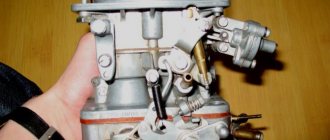
Oil pump
The engine lubrication system circuit includes an oil pump. It is used to pressurize the lubricant into the system. The drive of the device is mechanical, carried out from the crankshaft or camshaft of the power unit.
The pump inlet communicates with the crankcase cavity or a separate lubricant reservoir. The outlet is connected to the main line of the motor. The devices come in various designs. The most commonly used pumps are gear type. They are reliable and unpretentious to the conditions of use.
When the power plant operates, the gears of the unit rotate. The lubricant, falling on the gears, moves to the main line. Thanks to this design, pressure is created in the system.
Bypass mechanism
The design of the internal combustion engine provides for a bypass mechanism. It is designed as a one-way valve. When the pressure in the main line exceeds, the bypass mechanism opens and allows part of the lubricant to flow into the crankcase pan.
Oil receiver
Used to collect oil from the oil pan. The oil receiver is connected to the pump inlet. The connection between the pump inlet and the oil receiver is sealed. This prevents air from entering the system.
Filter
During operation of the power unit, the lubricant is cleared of metal shavings and contaminants. Cleaning is carried out using coarse and fine filters. Fine filters are used in passenger cars. Rough cleaning is performed by a mesh installed on the oil receiver.
Diesel power plants are equipped with centrifugal-type coarse filters. They consist of a glass inside with a movable sprinkler installed. During operation, oil under pressure is sprayed onto the walls of the glass. Contaminants remain on the glass. The purified oil drains into the crankcase cavity.
Before entering the main line, the lubricant passes through a fine filter.
It consists of paper filter elements. Paper elements trap fine contaminants. If the fine filter element is heavily soiled, it must be completely replaced.
Staffing table
For any engine, the lubrication system includes:
- oil container (crankcase or separate tank);
- an oil receiver, which is an intake neck with a filter mesh to separate large foreign particles;
- lubrication pump;
- replaceable filter;
- pressure reducing valve (one or more);
- pressure meter;
- main pressure line and channels, usually integrated into parts of the power plant;
- dipstick for monitoring the lubricant level.
Additionally, the lubrication equipment may include: a temperature sensor, a level sensor, and lubricating nozzles. Sometimes the engine has an oil cooler. The capacity of the lubrication system of a passenger car depends on the type of power plant and its dimensions. Typically, the volume of oil poured is from 3.5 to 7.5 liters.