First of all, when the lambda fails and malfunctions, several tangible consequences appear in the car’s behavior:
- Increased fuel consumption
- Unstable operation of the car engine (jerks)
- The operation of the catalyst is disrupted (toxicity increases)
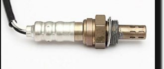
Then, to check the lambda probe, you can first unscrew it and carry out a visual check (just as a visual check of the spark plugs can tell you a lot).
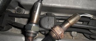
Visual inspection of the lambda probe
How to check the lambda probe. When you click on the image, it will open in full size
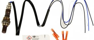
Several types of lambdas are installed on cars; the sensors can have one, 2, 3, 4, even five wires, but it is worth remembering that in any of the options, one of them is a signal (often black), and the rest are intended for heater (usually they are white).
Description and purpose of devices
Oxygen sensors, most often, are a galvanic system with a solid-state electrolyte, which enters the operating mode when heated above 300˚C. They are made using various materials as the electrolyte and have designs depending on their purpose.
The name λ-probes was given because this Greek letter denotes the coefficient responsible for the excess air in the internal combustion engine. With the best proportion of fuel and air in the engine cylinder (maximum efficiency is achieved with minimal fuel consumption), the ratio of the flow rate of the air mixture used to the stoichiometric (optimal): λ = 1. With this indicator, the car engine operates in an economical mode and the best efficiency of the catalyst is achieved, eliminating harmful substances from exhaust gases.
The purpose of the sensors is to control oxygen or residual fuel in exhaust gases for the operation of internal combustion engines and boilers in economical mode and to minimize harmful emissions of carbon monoxide, nitrogen oxide, and hydrocarbons using automation.
Solution of a problem
How to safely unscrew the lambda probe will depend on the reason why problems arose with dismantling this part. If the sensor is stuck, then very often this problem is solved using a gas burner. The main condition for successful removal of a part in this way is strong heating of the collector next to the sensor. Due to thermal expansion, the seat will expand slightly, after which we remove the main part using a wrench.
To remove a sensor with licked edges, you may need a welding machine. To remove a part, you will need to sacrifice a wrench or a socket head, which, after being placed on the edges of the part, is carefully grabbed in several places. Then you should use a large lever to rotate the DC in the mounting hole. In most cases, such an operation is performed on completely dismantled elements of the exhaust system.
In what systems are they used?
Oxygen sensors allow you to measure the volume fraction of oxygen in gases present after fuel combustion in internal combustion engines and boilers operating on solid fuel or methane.
λ-probes are used in instruments that measure the proportion of oxygen in the flue gases of boilers at thermal power plants and other industrial enterprises for the best adjustment of the efficiency of fuel combustion by supplying air to the furnace, depending on the instrument readings.
Sensors are most widely used in the automotive industry for automatically adjusting the supply of gasoline-air mixture to engine cylinders.
Electronic lambda probe test
You can find out about the condition of the lambda probe by checking it on professional equipment. An electronic oscilloscope is used for this. Some experts determine the performance of the oxygen sensor using a multimeter, however, it can only state or deny the fact of its failure.
The device is checked during full engine operation, since at rest the sensor will not be able to fully convey a picture of its performance. In case of even a slight deviation from the norm, it is recommended to replace the lambda probe.
Classification, device and principle of operation
Sensors are divided into types depending on the material of the active elements, the presence of a heating system, design features and principle of operation. Let's consider the existing types of probes.
Zirconium
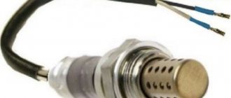
For this type of sensor, zirconium dioxide serves as the solid electrolyte of the galvanic system - a ceramic membrane permeable to oxygen ions, which exhibits operating properties at temperatures above 300˚C. The solid-state zirconium tip is coated with a thin layer of yttrium oxide for better permeability of oxygen atoms, and on the outer and inner sides it is partially coated with a thin layer of platinum, which acts as electrodes. Using the example of Fig. 1, let us consider a cross-section of a λ-probe.
Fig.1
- Wires: signal and heater power.
- Heating wire contact plate.
- A steel body connected to a casing that is threaded into the socket of the exhaust pipe opening.
- Zirconium electrolyte with outer and inner platinum electrode plates.
- Heater.
- Ceramic heat insulating element.
- Contact plane.
- Metal housing with holes for flue gases to enter.
Principle of operation
It's pretty simple. In the inner chamber of the working element with a platinum electrode there is ordinary air, which has a standard (reference) oxygen permeability with its own pressure on the walls of the zirconium tip when it is heated to 350-400˚C.
The outer platinum electrode receives exhaust gases, making the permeability variable, depending on the volume of oxygen in these gases. The potential difference on the electrodes appears due to the movement of oxygen ions from the side of higher pressure to the side with lower pressure.
A sharp voltage drop (from approximately 850 mV to 75 mV) when the presence of oxygen in the exhaust changes from a mixture with excess fuel and a lack of oxygen (rich, where λ<1) to a mixture with a lack of fuel and excess oxygen (lean, where λ>1) , allows you to make measurements with an error of about 5%.
Titanium
The working element of this probe is titanium dioxide. The sensor design is similar to zirconium, but does not require a chamber with a reference air mixture. The operating principle is based on a change in the resistance of the material when the volume fraction of oxygen in the exhaust changes. The more oxygen ions, the greater the resistance that occurs in the working element. For the system to function, a high heating temperature of titanium dioxide (over 600˚C) and a constant power supply to the electronic control unit - 5V are required.
Advantages of titanium probes:
- Durability, small size.
- There is no chamber with a reference comparative mixture, which increases their durability.
- Quickly achieve heating and working condition.
The disadvantages include a higher price than zirconium, which has led to the refusal of car manufacturers to use them in modern models.
Broadband – LSU sensors
With a wide measurement range in areas with different excess air ratios (λ<1; λ>1), oxygen probes of this design are universally used in various types of engines (gas, diesel, internal combustion with positive ignition) and heating installations. The broadband device more accurately sends a signal to the electronic control unit about the ratio of the presence of oxygen and fuel in the exhaust gases of the internal combustion engine, which allows better control of the level of emissions.
In appearance, the probe is similar to zirconium, but the operating principle is slightly different. The operation of the system is based on maintaining a constant potential difference between the electrodes within 0.45 V, corresponding to an excess air mixture ratio of unity.
The sensor consists of two working elements - zirconium, which performs a measuring function, and an element for introducing or removing oxygen from the system. Between the working elements there is an elongated hole, ranging in size from 20 to 50 microns. Two electrodes are placed in the hole for measuring and adjusting (pumping) the volume fraction of oxygen. A barrier is inserted into the measuring hole, separating it from the exhaust gases and regulating the injection or pumping of oxygen from it. The zirconium element is in contact with the external atmosphere thanks to a small supply channel.
If the mixture supplied to the engine is lean in fuel, then the exhaust gases are rich in oxygen and it is removed from the measurement hole using a positive voltage to the output working element. Otherwise, a voltage with the opposite sign is applied to the element, oxygen enters the measuring hole.
The electronic circuit strives to maintain a voltage of 0.45 V through a constantly changing voltage on the electrodes of the element for introducing/removing oxygen from the system so that the oxygen concentration in the hole corresponds to: λ = 1. A heater is built into the sensor to achieve a temperature of 700˚C and higher, depending depending on the type of probe.
pros
The advantages of broadband probes include:
- Wide range of measurements and regulation of oxygen in the exhaust.
- Quick heating and activation when starting the car.
- Wide range of applications.
It should be noted that lambda probes come with 2, 3, 4, 5 leads. Devices without heating usually have 2 terminals - signal and ground. Broadband devices have 5 or more pins.
Diagnostic methods
It is advisable to carry out diagnostics of the sensors every 10,000 km of the vehicle or at the first signs of a probe malfunction, which are described below.
Multimeter
Very often, the reason for the oxygen probe not working is damage to the heater coil or contact with the heater. It is easy to check whether this is true with a multimeter by switching it to the ohmmeter operating mode. Typically, pins 3 and 4 (in a 4-wire sensor) go to the heating element. The resistance value should be within 4.5 - 5.5 Ohms. If the readings exceed this value, the probe requires replacement because the heating element has failed.
To check the signal received by the electronic unit, you need to start the car, press the gas pedal to keep the engine in high-speed mode for some time. We connect the signal wire of the probe (usually black) to the positive probe of the multimeter, and connect the negative probe to ground, switching the device to voltmeter mode (2000 mV). When you hold down the gas pedal and suddenly release it, the readings of the device should be in the range from 1000 mV to 100 mV. If the readings remain unchanged within 400 - 500 mV when manipulating the gas pedal, then the probe is faulty.
Oscilloscope
The quality of testing with an oscilloscope is manifested in the ability to find out the time period of change in the output voltage signal. To check, you need to connect the oscilloscope to the wire that gives a signal to the electronic unit (black). Next, you need to start the engine and wait until it warms up to 70˚C. As the sensor warms up to 400˚C, the device will begin to show a wave-like graph. When the engine is running at about 3000 rpm, the device should show a smooth wave-like graph with a low signal level limit (at least 0.1 V) and a high signal level (no more than 0.8 - 1 V).
If a graph is drawn on the screen at the extreme (upper or lower) points, as well as at a position of about 0.6 V at maximum engine operation, then the λ probe is faulty.
Recommendations
Comments 6
Bygygy. Soldering is not the same. Only welding, only hardcore =)
Seriously, no matter how much I did anything with wires in machines, I always ended up with either twisting with soldering, or crimping with soldering. And, then (if there is a need, of course), having additionally fixed it, prevent the wire from breaking along the soldering boundary - for example, by heat-shrinking it on top in two layers of different lengths, or by wrapping electrical tape in a wider area.
But I’m focusing on how it was from the factory. It’s not just that they don’t recommend soldering the lambda wires (close to the lambda itself), it’s not just that the brush cables in the brush assembly are crimped or welded, etc.? In some places it’s a technological issue – in the sense that it’s easier to produce, and in others it’s a question of reliability.
In general, I think there is no need to generalize too much =) You just need to figure out how the solder joint will feel in a particular place. Bends, vibrations of different amplitudes and frequencies, temperature, humidity, chemical exposure (salt from the road, oil, antifreeze), etc.
In the brush assembly - this is understandable; soldering is not allowed due to the presence of huge currents during operation, which in case of overload will simply melt the solder, so there is crimping and welding.
But what about the fact that soldering does not like vibration and will definitely fall apart? Only crimp, only crappy contacts! :))))) I solder everything into the car myself, nothing has ever fallen off.
I, too, am their sect of godless shareholders, Nikolai.
I could barely find the pinout of this connector on the internet. What happened was that my brother-in-law and I were changing the gasket for the sub-panel and he didn’t remove the connector while I was twisting my pants (trying) Well, in short, all the wires fell out of it. He silently collected and stuck it in, but collected it without knowing how or what. In short, I mixed up all the wires. I only found out later. Now sometimes the check pops up. Covered the sensor?
Main reasons for failure
There can be many reasons for the breakdown of the oxygen sensor, among them, of course, the quality of the fuel used. Let's look at the main ones:
- Damage or shaking of the probe due to careless driving (hitting an obstacle, a hole).
- Probe overheating due to a malfunction in the ignition unit.
- Clogging of the ceramic surface with combustion products of low-quality gasoline.
- Engine malfunction (oil getting into the exhaust).
- Short circuit in the sensor wires.
Sensor failure can occur gradually, causing the engine to malfunction. On modern cars there is a second probe after the catalyst, which improves the quality of the internal combustion engine and protects the atmosphere from fuel combustion products.
2014-11-12
Oxygen sensor: four wire colors
For mainstream (narrowband) four-wire oxygen sensors, two wires are used for the signal, and the remaining two are used for the heating circuit. The heating circuit is easy to find - it is two wires of the same color. Those. First we find the same colors, and the purpose (decoding) of the remaining two is determined according to the options typical for Japanese cars:
Black wires of the heating circuit
1. Blue - signal, white - ground (a very common option for Japanese cars, Denso sensors). 2. White - signal, green - ground (Honda).
White wires of the heating circuit
1. Black - signal, gray - ground (typical option for substitutes, used by Bosch sensors and others). 2. Black - signal, red - ground (occasionally happens).
We are, of course, talking about the wires from the sensor itself to the connector. Further colors can be very different.
The Jimny uses Denso's scheme: two black, blue and white.
Connection nuances
If the device breaks down, you can install a sensor recommended by the manufacturer or a similar zirconium probe. Here are the basic rules:
- The colors of the sensor wires vary, but the color that supplies the signal to the electronic circuit is always dark.
- “Earth” comes in yellow, white, and gray shades.
- To connect a 4-wire probe in place of a 3-wire probe, connect the ground wires of the heater and the negative signal system to the ground of the car. The heater wire is connected through a relay circuit to the positive pole of the battery.
Connecting a new probe would be better done by a specialist from a car service center.
Bosch oxygen sensor pinout
How to check the lambda probe and signs of malfunction? Will a Bosch universal fit?
- The car jerks when you drive at low speeds - 1 answer
First of all, when the lambda fails and malfunctions, several tangible consequences appear in the car’s behavior:
- Increased fuel consumption
- Unstable operation of the car engine (jerks)
- The operation of the catalyst is disrupted (toxicity increases)
Then, to check the lambda probe, you can first unscrew it and carry out a visual check (just as a visual check of the spark plugs can tell you a lot).
Several types of lambdas are installed on cars; the sensors can have one, 2, 3, 4, even five wires, but it is worth remembering that in any of the options, one of them is a signal (often black), and the rest are intended for heater (usually they are white).
Tips and tricks
At the first signs of malfunction of the lambda sensor (the car begins to jerk sharply when starting to move, the gas pedal does not work so quickly, warning messages should be displayed on the panel, engine overheating during operation, unpleasant toxic gases from the exhaust pipe), you need to decide on some questions:
- Accurate detection of probe malfunction.
- Correct selection of a new sensor.
- You should not be tempted to install a used sensor (its remaining life is unknown) if you want to keep the engine in good condition.
- There is no need to try to disassemble the device; it is sealed and cannot be repaired.
It is advisable to buy an original probe or a universal one (for engines of a certain manufacturer).