Description of the structure of the box, the procedure for assembling and disassembling the Niva 2121 box, instructions for replacing bearings in the box of the Niva 2131, VAZ 2121. Maintenance and operation of the Niva 2121 box. Repair instructions for the cardan, axle and wheel drive Niva 2131.
Drain the oil from the gearbox, remove the fork and clutch release bearing (see the relevant sections).
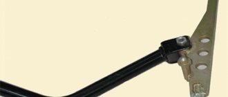
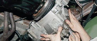
We remove the flange of the elastic coupling from the toe of the secondary shaft of the VAZ 2131 (see Replacing the secondary shaft oil seal)… …and the reverse light switch (see Replacing the reverse light switch). The gear selection mechanism can be removed from the vehicle without removing the gearbox. For clarity, these operations are performed with the gearbox removed.
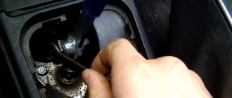
Remove the gear selector cuff. Set the gear shift lever to the neutral position.
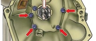
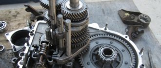
Using a 10mm socket, unscrew the three nuts securing the gear shift lever housing... ...and remove the gear selection mechanism. The connection is sealed with a gasket. We use a marker to mark the relative positions of the washers and the guide plate of the mechanism. Using a 10mm socket, unscrew the two nuts securing the reverse locking plate, holding the bolts with a wrench of the same size... ...and remove the locking plate. Having unscrewed another nut,... ...remove the lower guide plate washer. Having taken out one guide bar with two springs,... ...remove the guide plate from the lower end of the lever. Remove the upper guide plate washer. Remove the gear shift lever housing. We remove the rubber sealing rings of the bolts from the grooves of the housing. Remove the lower ball joint housing gasket. Remove the flange with the protective cover... ...and the upper housing gasket. Using pliers, remove the retaining ring. Remove the washer and spring. Remove the spherical washer... ...and separate the lever and the ball joint housing. We install the gearbox with the clutch housing on the workbench. Using a 10mm socket, unscrew the ten nuts securing the lower gearbox cover. Remove the cover... ...and the sealing gasket. Using a screwdriver, through the hole in the gear selection mechanism, we move down the fork rod for selecting 1st–2nd gears (this engages 2nd gear). Using a 13mm wrench, unscrew the rear cover fastening nut located inside the box body. Using a 13mm wrench, unscrew the five nuts securing the back cover located outside the case. We tap the cover bosses with a hammer, while using a screwdriver (or a suitable piece of pipe with the secondary shaft oil seal removed) hold the rear bearing on the secondary shaft of the VAZ 2121. Slide the cover off the studs and remove it, turning it clockwise (looking from the side of the secondary shaft shank), to prevent the cover from touching the rods and gear block of the 5th gear and reverse gear. Remove the cover gasket. To replace the bearing of the 5th gear and reverse gear block... ...pry up the bearing rollers with a screwdriver... ...and remove the rollers from the separator. We remove the separator. Using a hook to hook the outer ring of the bearing,... ...take it out of the rear cover socket. Remove the thrust ring of the rear bearing of the secondary shaft. Remove the outer ring of the bearing with the cage and rollers. Remove the inner race of the bearing. Remove the spacer sleeve... ...and the oil deflector washer. To stop the shafts from turning, it is necessary to engage two gears. 2nd gear was engaged when the rear cover was removed. Before engaging reverse or V gears, we release the fork for selecting these gears of the VAZ 2131. To do this... ...with a “10” wrench, unscrew the bolt securing the fork to the rod. Pressing the screwdriver down on the fork, engage reverse gear. Using a 17mm spanner (head), unscrew the bolt securing the fifth gear and reverse gear block. We take out the bolt... ...and remove the gear block from the splines of the intermediate shaft. We clamp the block of 5th gear and reverse gears in a vice with soft metal jaw linings. Using two screwdrivers, press the inner ring of the gear block bearing... ...and remove the inner ring. We remove the 5th gear gear bushing,... ...the gear itself with the synchronizer blocking ring,... ...the hub... ...and the synchronizer clutch. By turning the 5th gear and reverse fork on the rod to the secondary shaft of the VAZ 2121,... ...remove the reverse gear intermediate gear. Using a 13mm spanner, unscrew the two bolts securing the clamp cover. Remove the cover and gasket. We take out the springs of the clamps (the rod spring of the 5th gear and reverse gear is longer than the other two and has a dark coating color). Using a magnetized screwdriver, remove all three latches. We take out the 5th gear and reverse gear shift rod with the fork. Remove the plug from the rod. Using a magnetized screwdriver, remove the locking block from the hole in the gearbox housing, which is located between the crankcase sockets for the rods of 5th gear, reverse gear and 3rd–4th gears. Remove the reverse driven gear from the secondary shaft. We remove the key from the shaft groove. Using a 10mm socket, unscrew the bolt securing the 3rd–4th gear shift fork to the rod. We take out the rod. A locking block is inserted into the hole of the rod,... ...take it out. Using a magnetized screwdriver, remove the locking block from the hole in the gearbox housing, which is located between the crankcase sockets for the rods of 1st–2nd and 3rd and 4th gears (this block is noticeably longer than the block located between the 5th-reverse gear engagement rod and the 3rd–4th gear engagement rod) . Using a 10mm socket, unscrew the bolt securing the 1st-2nd gear shift fork. We take out the rod. Using an impact screwdriver with a Phillips head, unscrew the three screws securing the locking plate of the secondary shaft intermediate bearing. The screws are secured with special washers. Remove the locking plate. Using a 19mm wrench, unscrew the nut securing the reverse intermediate gear axle, holding the axle from turning with a 24mm wrench. We take out the axis of the reverse intermediate gear. Having unscrewed the nuts securing the clutch housing (see Replacing the input shaft oil seal),... ...separate the clutch housings and gearboxes. We remove the gasket. Remove the spring washer with a conical surface from the input shaft (its smaller diameter faces the bearing). We clamp the splined part of the input shaft in a vice with soft metal jaw linings. Using a 19mm spanner, unscrew the bolt of the clamping washer of the front bearing of the intermediate shaft. Remove the bearing clamp washer. Using two screwdrivers, pry the front double-row bearing of the intermediate shaft by the mounting ring... ...and remove the bearing. When a bearing is removed, its rear inner race may remain on the shaft. Use two screwdrivers to compress the rear inner race of the bearing... ...and remove it. We take out the thrust ring of the rear bearing of the intermediate shaft. By inserting a screwdriver between the ends of the bearing and the first gear gear of the intermediate shaft, we move the rear bearing. We take out the outer ring of the bearing with the cage and rollers. Remove the inner race of the bearing from the shaft toe. By moving the intermediate shaft back,... ...we remove it from the gearbox housing. Using two screwdrivers, pry the rear bearing of the input shaft by the mounting ring and... ...take out the input shaft assembly with the bearing and the synchronizer blocking ring. Use pliers to open the retaining ring... ...and remove it. Remove the spring washer. We rest the end of the outer ring of the bearing on the jaws of the vice. Using a hammer with a plastic striker, we strike the end of the input shaft... ...and press the bearing. Use pliers to open the mounting ring... ...and remove it. Having moved the synchronizer locking ring, use pliers to open the locking ring... ...and remove it. Remove the blocking ring... ...and the synchronizer spring. The blocking rings of the synchronizers of other gears are removed in the same way.
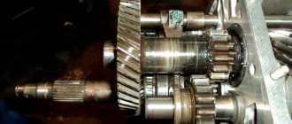
Remove the needle bearing from the front toe of the secondary shaft. Remove the shift forks for 1st and 2nd, 3rd and 4th gears. Using two screwdrivers, pry the intermediate bearing of the secondary shaft by the mounting ring... ...and remove it. Having tilted it, we remove the secondary shaft assembly from the gearbox housing with gears, couplings, hubs and blocking rings for Niva 2131 synchronizers. Remove the bushing and 1st gear gear assembly with the blocking ring from the rear side of the shaft. Remove the bushing from the gear. Remove the synchronizer clutch for engaging 1st and 2nd gears. Remove the synchronizer hub. Remove the 2nd gear gear assembly with the blocking ring. From the front end of the secondary shaft, remove the synchronizer clutch for 3rd and 4th gears. Clamping the secondary shaft in a vice with soft metal jaw pads,... ...use pliers to remove the retaining ring. Remove the spring washer (it is installed with the convex side towards the front end of the shaft). We remove the synchronizer hub for 3rd and 4th gears... ...and the 3rd gear gear assembly with the synchronizer blocking ring. We assemble the gearbox in the reverse order. If, when removing the front double-row bearing of the Niva 2121 intermediate shaft, its rear inner ring remains on the shaft, then the bearing must be assembled before installation. To do this, from the outer ring of the VAZ 2121 bearing...
Using a screwdriver, carefully remove the separator with the balls... ...and put it on the inner ring (removed from the shaft). We insert the separator with balls and inner ring into the outer ring of the bearing. When assembling the input shaft... ...using a suitable piece of pipe, press the bearing onto the shaft, resting on its inner ring. After installing the secondary and intermediate shafts into the gearbox housing, we press in the front and rear bearings of the intermediate shaft, the intermediate bearing of the secondary shaft and the inner ring of the bearing of the Niva 2131 gear block. pipes) into the rear cover socket. We insert the separator and rollers into the outer ring of the VAZ 2131 bearing. To prevent loosening of the bolt securing the fifth gear and reverse gear unit, apply thread sealant to the bolt threads. For ease of installation of the rear cover, we install the rear bearing assembly on the secondary shaft. It is advisable to lubricate all sealing gaskets with a thin layer of silicone sealant. When assembling the Niva 2121 gear selection mechanism, we apply Litol-24 lubricant to the ball joint.
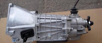
Features of the gearbox on Niva
VAZ 21213 car with an engine capacity of 1.7 liters. can develop power up to 79 horsepower. Fuel consumption averages 10 liters per 100 km. As is typical for gasoline engines, there is a central injection system. Such vehicles should be fueled with AI-95 gasoline.
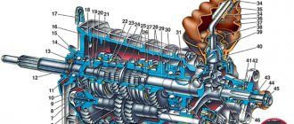
The Niva gearbox (VAZ 21213) is a five-speed manual transmission. The Niva's transmission has permanent all-wheel drive. It should be noted that there is a reliable gearshift lever extension on the Niva. Thanks to it, speed modes can be changed quickly. The existing camshaft drive is chain driven. The crankshaft includes several connecting rods and main journals. The crankshaft is distinguished by its durability and is made of cast iron. The timing mechanism is covered with a cover. There is an oil filler neck here.
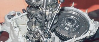
Niva checkpoint diagram
A transfer case is installed on the Niva 2121. Its peculiarity is that it has both high and low gears. It is important to use an increased one if you need to save on fuel consumption. In the event that movement occurs over rough terrain, a lower gear helps out. However, in this case, fuel consumption will increase.
Transfer case diagram
The transfer case allows you to disable one of the drive axles if necessary. The transfer case includes shafts, a differential, and a gearshift clutch. The main failures are expressed in the fact that over time its main components wear out, as a result of which the box may overheat and problems with switching on the bridge may appear. Repair of the VAZ 21213 gearbox is required if characteristic vibration from this unit begins to be observed.
Thus, the popularity of the car is explained by the fact that it has an all-wheel drive system. The speed box diagram shows that it includes a large number of components that interact with each other, ensuring excellent performance of the car.