02/28/2022 6,254 Dashboard
Author: Ivan Baranov
Every modern car must be equipped with a tachometer. This device is a device designed to measure crankshaft rotation speed. Like any other device, this device can fail over time. How to check the tachometer at home, and for what reasons it may fail - look for answers to these questions below.
[Hide]
How to check the tachometer yourself? Methods, tips and tricks
Not many drivers know how to check the tachometer - one of the most important instruments in a car, which allows you to measure the number of engine revolutions.
With its help, the driver can maintain full control over the operation of the engine so that the speed does not exceed the permissible values, and the engine does not fail in the future, since its repair will cost car owners a pretty penny. In other words, its main function is to simplify the selection of the desired gear, which is necessary for the correct operation of the engine and extending its service life. If the instrument needle enters the red zone, it is recommended to immediately engage an upshift. The tachometer can also be used to adjust engine idle speed.
If the tachometer suddenly fails and its needle either lies or does not show any values at all, then this problem must be solved as soon as possible. Naturally, first you need to find out the reason why it stopped working.
What to do if the tachometer does not work
The car's dashboard displays all the parameters necessary for the driver to operate the vehicle comfortably and safely. One of the most important indicators is the rotation speed of the crankshaft, which is measured using a tachometer.
This parameter allows you to control the load to which the engine is exposed and change gear in time. If the rotation indicator is not displayed or the result is unreliable, you need to find out why the tachometer is not working and determine the main ways to restore the damaged sensor.
Causes of malfunction
How to check the tachometer, especially if it is electronic and has an LED screen? First of all, you need to know that when the engine runs for a long time, harmful vibration occurs, which can lead to various types of damage to the devices and systems of the car. The tachometer cannot always avoid this fate. Basically, this could be a broken display, which will need to be replaced if it malfunctions.
Visible causes of problems must be eliminated immediately. This may be damage to the insulation of the electrical wiring, disconnection of wires from the tips, and, as a result, loss of contact. If the wires are severely damaged, they must be replaced in such a way that relapses do not occur. If the sensor that is responsible for the number of engine revolutions breaks down, the needle begins to jump in different directions. This is a fairly common problem and can be solved by simply replacing the tachometer.
We looked at the most common reasons
tachometer failure. Eliminating such problems allows you to restore normal operation of the tachometer. If checking the tachometer was unsuccessful and the diagnostics did not bring any results, then you need to seek help from specialists at a service station.
Reading the readings
To measure voltage, you need to switch the multimeter to voltmeter mode and connect one sensor to the circuit and ground the second.
When using a multimeter, you must correctly connect its contacts to the system components. The connection method depends on the polarity of the vehicle. In a car with negative grounding, it is necessary to connect the contact marked (-) to the body, and in a car with positive grounding, the contact marked (+) must be connected to the body. Refer to the instruction manual to check polarity.
Make sure that the contacts are securely fastened, and if necessary, clean them of rust and paint so that the readings are accurate. Sandpaper works well for cleaning.
Working in the engine compartment, attach the sensor to the ground clamp on the battery
How to replace a faulty tachometer yourself?
Before connecting the tachometer to the engine, you need to select the same device that was installed before the breakdown, or a similar device that will be exactly suitable for the type of your engine.
Typically it is red
. The tachometer input wire must be connected to the distributor or to the switch, which depends on what ignition system is installed on the car. Don’t forget to also connect a wire to the size switch so that the device is illuminated.
If you don’t know how to check the tachometer and find out how accurately it works, then you can install a digital analogue in your car, which has a higher accuracy class. A proven pointer gauge when driving at speed is visually perceived much better than a digital tachometer.
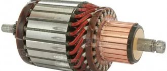
Operating principle of magnetic tachometers
The operation of a magnetic tachometer is based on the phenomenon of induction of eddy currents (Foucault currents) in a non-magnetic disk by a rotating constant field. In its normal state, an aluminum or copper disk does not have magnetic properties, but if you place it in a rotating magnetic field, eddy currents arise in it. These currents interact with the magnetic field, so the non-magnetic disk also begins to rotate after the magnet.
To operate the tachometer, an arrow is attached to the disk, on the shaft of which a return spring is attached. The magnet is connected to the crankshaft or one of the transmission shafts via a flexible shaft. The higher the engine speed, the faster the magnet rotates, and the higher the force deflecting the non-magnetic disk fixed by the spring - all this is reflected in the position of the arrow.
Advice from professionals on how to test the tachometer yourself for functionality at home
Every modern car must be equipped with a tachometer. This device is a device designed to measure crankshaft rotation speed. Like any other device, this device can fail over time. How to check the tachometer at home, and for what reasons it may fail - look for answers to these questions below.
Main types
Car tachometers are classified depending on the type of design. There are analogue and digital types. There are also mechanical tachometers, but they are not currently used in the automotive industry. These sensors were installed on the first vehicles.
- Analog. They are considered more convenient and reliable. When displaying the number of revolutions, a mechanical dial with an arrow moving along it is used. The design includes a motion sensor that responds to shaft rotation. When registering revolutions, an electrical impulse is created, which subsequently overcomes the converter and causes the dial hand to move to the desired speed value. Despite a number of advantages, analog tachometers are considered less accurate.
- Digital. The sensor reads the speed of revolutions, creating numerous pulse signals. They are processed in an analog-to-digital converter and later displayed on an electronic dial or on-board computer screen. Digital models are equipped with their own microprocessor and are much more accurate than analog ones. Used on most cars manufactured after 2000.
Analog tachometers are considered obsolete. Therefore, they are found mainly in outdated cars. Unlike digital ones, they are less resistant to loads and fail more often.
In modern cars, instruments for measuring engine speed can be synchronized with other sensors. This is necessary to adjust the power and intensity of the engine, taking into account the current speed, quality of the road surface, climatic conditions, temperature and other factors. The latest cars with automatic gearboxes are equipped with similar technologies.
Possible malfunctions: signs and causes
The only sign that can indicate a malfunction of this device is sudden jumps in the instrument needle or its position at the zero mark.
For what reasons can this happen:
- Mechanical damage to the screen. Of course, if the display is damaged, it will have to be replaced; there are no other options.
- Problems in the wiring, poor functionality of the contact group as a result of oxidation. Such a problem can lead to disruption of the source of signal transmission that comes from the power unit to the device.
- In addition, the reason may be damage to the insulation of high-voltage wires connected from the distributor to the spark plugs. Such problems can lead to a lack of contact. If the cable is severely damaged, it must be replaced.
- Failure of the crankshaft sensor. If this controller breaks down, the instrument needle will jump sharply in different directions. This reason is one of the most common. The only solution in this case is to completely replace the device.
- Using silicone high-voltage cables instead of conventional ones.
Photo gallery “Types of tachometers”
Replacement instructions
Replacing the sensor is not difficult; it is usually secured in the gearbox housing with a screw to the flange. By unscrewing this screw and removing the connector, the sensor can be removed and a new one installed.
A standard gasket or sealant is used for sealing. After replacement, you need to reset the current errors using a scanner or briefly removing the terminal from the battery.
Before carrying out the operation, you must thoroughly clean the box housing around the sensor to avoid abrasives getting into the crankcase. Adjacent surfaces are wiped free of dirt, oil and oxides.
Source
Diagnostics
If the first symptoms of a breakdown appear in the operation of the tachometer, then first of all it is necessary to diagnose the condition of the electrical circuits. As stated above, the reason may lie in poor contact or its absence, as well as damage to the circuit. Therefore, you need to check the connection, as well as the integrity of the cables. If even minor defects are detected, such as traces of corrosion, minor damage or cracks, weak fixation, the problem must be corrected, for example, using electrical tape. More serious defects require wiring replacement.
As practice shows, most often our compatriots are faced with tachometer inoperability after replacing the standard ignition cables with silicone ones. The device begins to work incorrectly as a result of the fact that silicone high-voltage devices have a different resistance value. In particular, in this case the shape of the signal changes. This problem can be solved by reducing the resistor on the CP circuit. If we talk about digital devices, then one of the most common malfunctions is the failure of the display (the author of the video is the liudusa channel).
This problem can only be solved by replacing the screen.
How to check a device if its needle jumps:
- Pay attention to the control panel to see if the Check Engine indicator lights up on it. If the lamp does not appear, checking the system will not reveal the problem.
- Check the integrity of the wiring using the voltage diagnostic method on the positive and negative contacts. In addition, make sure that all connections are securely connected.
- In the event that other devices are not functioning correctly, it is imperative to also check the mass, since this point is often missed. If the weight is bad, the tachometer will also work intermittently.
- If no defects are found, then it is also necessary to diagnose the condition of the contacts on the switchgear, that is, the distributor. You should also check the capacitor on the cap as it may be broken.
- Since high-voltage circuits are one of the main causes of malfunctions, it is necessary to check their integrity. In addition, all circuits in the ignition system are tested.
- If you changed the tachometer or repaired it, calibrating the device may solve the problem. To make the adjustment, adjust the position of the steering wheel or the device itself, check the correctness and quality of the connections.
- When the needle drops sharply as the speed of the power unit increases, most likely the cause should be looked for in the switch. Apparently, it is out of order and needs to be replaced.
Operating principle of the speed sensor
In fact, the DS measures not the speed, but the rotation frequency of the part on which there is a ring gear. This value can be converted into speed mechanically or electronically, since the transmission has an unambiguous and known relationship between frequency and speed for the standard wheel size.
Installing tires or wheels of a different size will result in a speed measurement error. As well as modifications to the transmission with changes in gear ratios after the DS.
Sensors can be mechanical or electronic. Mechanical DS is no longer used; previously it consisted of a gear-type device ending with a cable in a sheath. The rotation of the cable was transmitted to the dashboard, where a magnetic system was connected to it.
The alternating magnetic field induced currents in the coils, which were measured with a dial milliammeter calibrated in speed values.
The resulting speedometer was usually combined with a mechanical revolution counter - an odometer that recorded the total and daily mileage of the car.
Electronic sensors can operate using different principles:
- optical, when the beam passes through slits in a rotating disk;
- a magnetoresistive, rotating multi-pole magnet causes a change in the electrical parameters of the sensing element;
- induction, metal parts cyclically change the field of a permanent magnet, which causes an alternating current in the measuring coil;
- based on the Hall effect, an alternating magnetic field is fixed by a magnetically sensitive semiconductor crystal, after which the shaper creates a sequence of pulses convenient for operation of the receiving units.
Most often in modern technology, devices with the Hall effect and a built-in magnet are used, capable of “counting” the passing teeth of any metal crown.
Posts 1 page 20 of 20
Share103.02.2010 22:35
- Author: scarabaeus
- Administrator
- From: Mari El
- Registered: 07/21/2009
- Posts: 4206
- Respect: [+39/-2]
- Positive: [+11/-0]
- Gender: Male
- ICQ: 438271971
- Awards: admin
- Car: OOO
at home? it has three contacts, I seem to have tracked the minus, but how do you know what to connect the other two to?
Share204.02.2010 11:03
- Author: SCH
- Administrator
- From: Omsk
- Registered: 07/21/2009
- Posts: 6578
- Respect: [+74/-2]
- Positive: [+50/-0]
- Gender: Male
- Age: 38 [1981-03-23]
- ICQ: 219880120
- Awards: admin, starosta
- Car: 1.6SA/1986/red-sold
it has three contacts, I seem to have tracked the minus, but how do you know what to connect the other two to?
It seemed like it was written on my flex board
Share304.02.2010 11:12
- Author: scarabaeus
- Administrator
- From: Mari El
- Registered: 07/21/2009
- Posts: 4206
- Respect: [+39/-2]
- Positive: [+11/-0]
- Gender: Male
- ICQ: 438271971
- Awards: admin
- Car: OOO
It seemed like it was written on my flex board
sure, there is a signature
Share404.02.2010 13:11
- Author: Den-89
- Active participant
- From: Omsk
- Registered: 12/25/2009
- Posts: 155
- Respect: [+0/-0]
- Positive: [+0/-0]
- Warnings: 1
how do you know if he says it right or not?
Share504.02.2010 13:20
- Author: hrak
- Active participant
- From: Belarus
- Registered: 01/28/2010
- Posts: 660
- Respect: [+43/-1]
- Positive: [+0/-0]
- Gender: Male
- Age: 45 [1974-05-02]
- Awards: otziv
Colleague Den-89 , in fact, a tachometer is a frequency meter. There is such a device in radio electronics. Therefore, if you apply a signal with a certain amplitude, say, 1,000 Hz from a square pulse generator, then in theory, the tachometer should show 1,000 rpm. But I wrote this offhand, without thinking.
The importance of checking the tachometer
Using the indicator, the driver can fully control the operation of the engine. It is important that the number of revolutions does not exceed the permitted values, and the engine lasts much longer, because a car enthusiast can spend a significant amount on engine repairs.
You can repair or even replace the tachometer at home.
Thanks to the device, it is easier to select the desired gear for normal engine operation and increase its service life. When the needle enters the red zone, you must engage a higher gear. The device is also used to regulate idle speed.
If the instrument needle is lying or it does not give any readings, a tachometer check is required.
How to check the tachometer yourself? Methods, tips and tricks
Not many drivers know how to check the tachometer - one of the most important instruments in a car, which allows you to measure the number of engine revolutions. With its help, the driver can maintain full control over the operation of the engine so that the speed does not exceed the permissible values, and the engine does not fail in the future, since its repair will cost car owners a pretty penny.
In other words, its main function is to simplify the selection of the desired gear, which is necessary for the correct operation of the engine and extending its service life. If the instrument needle enters the red zone, it is recommended to immediately engage an upshift. The tachometer can also be used to adjust engine idle speed.
If the tachometer suddenly fails and its needle either lies or does not show any values at all, then this problem must be solved as soon as possible. Naturally, first you need to find out the reason why it stopped working.
How to check the tachometer
. especially if it is electronic and has an LED screen? First of all, you need to know that when the engine runs for a long time, harmful vibration occurs, which can lead to various types of damage to the devices and systems of the car. The tachometer cannot always avoid this fate. Basically, this could be a broken display, which will need to be replaced if it malfunctions.
One of the problems may be electrical wiring problems and deterioration of the contact group due to oxidation. This may lead to the source of transmission of operating pulses coming from the motor to the tachometer being disrupted.
Visible causes of problems must be eliminated immediately. This may be damage to the insulation of the electrical wiring, disconnection of wires from the tips, and, as a result, loss of contact.
If the wires are severely damaged, they must be replaced in such a way that relapses do not occur. If the sensor that is responsible for the number of engine revolutions breaks down, the needle begins to jump in different directions. This is a fairly common problem and can be solved by simply replacing the tachometer.
We looked at the most common reasons
tachometer failure. Eliminating such problems allows you to restore normal operation of the tachometer. If checking the tachometer was unsuccessful and the diagnostics did not bring any results, then you need to seek help from specialists at a service station.
How to replace a faulty tachometer yourself
Before connecting the tachometer to the engine, you need to select the same device that was installed before the breakdown, or a similar device that will be exactly suitable for the type of your engine.
Look at the wires of the old device: one black wire comes from it, which is negative, and it must be connected to the car body. The positive wire should be connected directly to the ignition switch.
General information
A tachometer is a device that measures the speed of rotation of rotating structural elements or individual mechanisms. This type of sensor is widely used in the automotive industry.
The main task of this device in the design of the machine is to measure the engine shaft speed. Also, some vehicles may use auxiliary tachometers, for example, to measure wheel speed.
Tachometers are used on vehicles with both manual and automatic transmissions. Using this device, the driver receives information about the functioning of the engine. It is read from the sensor and displayed on a screen or mechanical dial located on the dashboard. The unit of measurement is the number of revolutions per minute.
Each engine type has its own minimum and maximum load indicators. Therefore, the recommended number of revolutions varies. Deviation from normal rotation speed leads to accelerated wear of engine components, which increases the risk of premature breakdowns.
Monitoring engine operation taking into account tachometer data allows you to:
- increase the service life of the motor;
- reduce the load on the vehicle chassis;
- optimize fuel consumption;
- more effectively control the speed limit on different sections of the road;
- reduce the load on the transmission during gear changes.
The tachometer in a vehicle performs important functions, and therefore it is recommended to monitor the serviceability of this sensor and record violations in its operation.
Design, connection and repair of the VAZ 2106 tachometer
A tachometer is used to measure engine speed of exclusively carburetor cars.
This is a device located on the front panel.
It cannot be called super-important, but for a novice motorist who cannot yet hear the engine of his car, it helps to calculate the number of engine and crankshaft revolutions.
It also plays an aesthetic role.
Many car owners like to show off modern instruments on the control panel.
The VAZ 2106 has a four-stroke four-cylinder engine, and during 1 revolution of the ignition distributor rotor, the contacts of the breaker, the so-called distributor, open and close four times.
For one revolution of the rotor, four voltage pulses occur or 2 pulses for one revolution of the crankshaft.
Other VAZ models have different engines, so you need to take this into account when installing tachometers.
The measurement of impulses underlies the operation of the tachometer and directly depends on the engine crankshaft speed.
Important: each brand of car must have its own measuring device, otherwise the readings will be false.
Mechanism design
VAZ 2106 tachometer connection diagram
On a plastic case with a glass holder there is a milliammeter of the usual classical structure with an attached scale.
It shows the zones of dangerous crankshaft speeds in different colors: the preliminary zone (5500-6000) is highlighted in yellow, and the dangerous speed zone (more than 6000) is marked with red lines.
The device is uniformly illuminated by an AMN 12-3 lamp.
At the bottom of the scale there are three colored lights, indicating respectively: the amount of charge, oil pressure and the status of the parking brake.
Inside the tachometer there is a moving coil with a permanent magnet, thanks to which the pulse indicator needle is set in motion.
The device is electronic, so it is powered by the car's ignition.
Connecting the tachometer VAZ 2106
When purchasing a new pulse meter, instructions for connecting the device should be included.
You can also find installation diagrams in reference books for motorists.
But still, if you are not an experienced mechanic and have not dealt with electronics, contact a service station: for a small fee you will save your time.
From this video you will learn how to connect a tachometer! Enjoy watching.
And for those who want to engage in “self-medication”, the connection process diagram is quite simple:
- First, connect the brown wire to the “K+” terminal of the ignition coil. Pulses from the coil through this cord will control the tachometer readings
- We look for the thick red wire and connect it through the fuse to the ignition switch. The device will receive power from the battery.
- The next one is a white cable with a black stripe, which leads to the “minus”. It is used to connect to ground.
- white – connection of the device backlight
- black – connection to the charging relay (located on the right side under the hood of the car)
- gray with a black stripe – contact with the oil pressure sensor (located on the left side of the engine).
These are the three main wires.
Auxiliary ones are used for:
The most common device breakdowns
The TX-193, with its non-separable design, is a complex electronic device, so it is almost impossible to repair faults at home.
Most likely you will have to purchase a new device.
From this video, you will learn how you can modify the tachometer of the VAZ 2106. Let's take a look!
If the tachometer does not work: you need to check whether all relevant wires are connected correctly.
We ring the cable from the ignition coil and check the contact.
It is necessary to measure the current resistance.
Then we check the plus and minus outputs of the battery and the circuit between the ignition module and the tachometer contact.
Often, a malfunction can result from replacing the “original” high-voltage wires with silicone ones.
They have a different linear resistance and the pulse shape on the coil winding will change.
For a person with certain technical skills, it will not be difficult to check the device’s board.
To do this, we disassemble the case:
- unscrew the screws securing the housing and tachometer mounting
- disconnect the wires from the tachometer
- turn off the backlight
- unscrew and remove the remaining screws and nuts
- remove the body visor along with the glass
- carefully, using a screwdriver, remove the arrow
- Unscrew the screws on the instrument scale
- remove the temperature sensor pins from the holes in the board
- lifting the scale, we take out the tachometer.
We recommend that you read this article. from which you will learn how to install a subwoofer in a car.
You can find out how much a Solex 21083 carburetor costs here. You will also find unique material on our website about this device.
It is recommended to repair the tachometer exclusively at a car service center or service stations.
Experienced and knowledgeable technicians will be able to quickly identify the breakdown and fix it.
Otherwise, you risk being left without a device.
Some, let’s say: “jacks of all trades,” manage to make a housing for the meter from coffee cans, extend the wiring or replace cables. But such tuning, even for the sake of convenience or “bells and whistles,” is not recommended.
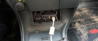
Subject In connection with the transition to an injection power system, a tachometer was purchased from an injection dashboard. Tachometer brand 24.3813.
I found this tachometer connection diagram online:
In + and – I connected power from a 12V transformer, and connected batteries of different voltages to the middle signal contact. The tachometer is absolutely indifferent to this.
Question: how to check its performance at home and what is the exact value of the input signal to the tachometer from the ECU?
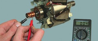
Using a mechanical tachometer
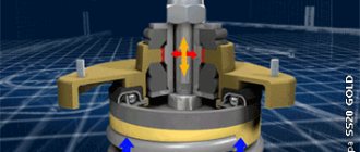
Very often it is necessary to determine not only the nominal characteristics of an electric machine, but also to know the exact number of revolutions at a given moment. This is done when diagnosing electric motors and to determine the exact slip coefficient. In electromechanical laboratories and in production, special instruments are used - tachometers. If you have access to such equipment, you can measure the rotation speed of an asynchronous motor in a few seconds. The tachometer has a pointer or digital dial and a measuring rod, at the end of which there is a hole with a ball. If you lubricate the centering hole on the shaft with viscous wax and press the measuring rod tightly against it, the exact number of revolutions per minute will be displayed on the dial.
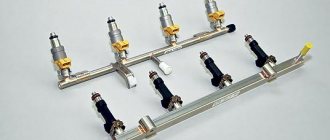
Fuel pressure sensor
The fuel pressure sensor is designed directly so that the ECU actually receives information about the value of this pressure. These devices are installed on both gasoline engines equipped with injectors and modern diesel engines with a Common Rail fuel system. These sensors are installed in the engine fuel rail. In both gasoline and diesel engines, the task of the fuel pressure sensor is the same, and is to ensure the pressure value within certain limits necessary for the normal functioning of the engine, ensuring its rated power, and normalizing noise during its operation. Some systems provide for the installation of two sensors - in high and low pressure systems.
Structurally, the sensor is a sensor element consisting of a metal membrane and strain gauges. The thicker the membrane, the greater the pressure the sensor is designed for. The task of strain gauges is to convert the mechanical bending of the membrane into an electrical signal. The output voltage value is about 0...80 mV.
If the pressure value goes beyond the specified limits (these values are stored in the memory of the electronic control unit), then the control valve in the fuel rail is activated in the system, and the pressure is adjusted accordingly. If the sensor fails, the ECU activates the Check Engine light on the dashboard and begins using standard (non-adjustable) fuel consumption values. This leads to the engine operating in a non-optimal mode, which is reflected in excessive fuel consumption and loss of engine power (dynamic characteristics of the machine).
You can read information about checking the fuel pressure regulator
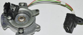
Camshaft position sensor
Similar to the DPKV, the camshaft position sensor (abbreviated DPRV) reads information about the angle of its position and transmits the corresponding information to the ECU. Based on the information received, the control unit makes a decision to open the fuel injectors at a certain point in time. Old injection engines (up to about 2005) did not have a camshaft position sensor installed. Because of this, fuel injection into the intake manifold on such engines was carried out in pairs-parallel mode, in which two injectors open simultaneously, which is characterized by excessive fuel consumption.
On engines on which DPRV is installed, so-called phased fuel injection is performed. That is, only one injector nozzle opens, where fuel should be supplied at the moment. As for the location of the sensor, on eight-valve engines it is mounted at the end of the cylinder head. On sixteen-valve power units, this sensor is also usually located on the cylinder head, near the first cylinder.
If the camshaft position sensor fails, the electronic control unit switches the engine to emergency mode, in which the injectors operate in pairs-parallel mode, opening simultaneously. This leads to excessive fuel consumption by 10...15%, in some cases the engine “troubles”. Typically, this generates an error signal in the ECU and activates the Check Engine light on the dashboard. Therefore, it is necessary to perform additional diagnostics using an electronic error scanner.
The DPRV sensor can be checked using a multimeter and/or an oscilloscope.
Oxygen concentration sensor
Another name for the sensor is lambda probe. The main task of the unit is to record the amount of oxygen in the exhaust gases. As a rule, it is installed next to the catalyst or on the exhaust pipe of the muffler. In some car models, the design provides for the use of two oxygen sensors - one before the catalyst, and the second after. The relevant information is traditionally transmitted to the electronic control unit, and it then makes a decision on the supply of fuel to the engine, adjusting the composition of the air-fuel mixture (poor/rich). If oxygen is detected in the exhaust gases, it means the mixture is lean; if not detected, it means it’s rich.
The oxygen sensor itself is quite reliable and rarely fails. However, if this happens, then the emission of harmful substances along with exhaust gases into the atmosphere increases. Externally, the failure of the lambda probe can be determined by increased fuel consumption. A conditional disadvantage of the sensor is its relatively high price compared to other car sensors.
Checking the oxygen sensor is carried out both visually and with a tester. The method of measuring voltage and sending a signal will depend on how many contacts a particular lambda has.
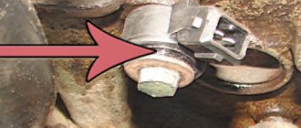
Coolant temperature sensor
It also has other names - temperature sensor, coolant sensor. As the name implies, its task is to record the temperature of antifreeze or antifreeze and transmit this information to the engine electronic control unit (ECU). Based on the information received, the control unit adjusts the richness of the air-fuel mass entering the engine; accordingly, the colder the engine, the richer this mixture will be. The coolant temperature sensor is most often located on the exhaust pipe of the cylinder head (although there may be other options, this depends on the specific car model).
Essentially, this sensor is a thermistor - that is, a resistor that changes its internal electrical resistance depending on the temperature of its control element. The lower the temperature, the higher the resistance, and vice versa, the higher the temperature, the lower the resistance. However, the sensor supplies the ECU with a voltage value rather than a resistance value. This is implemented by the sensor control system when a 5 Volt signal is supplied to it through a resistor with a constant resistance, which is located inside the control controller. Therefore, along with the resistance, the output voltage also changes. So, if the antifreeze temperature is low, the output voltage will be high, and as it warms up, the voltage will decrease.
Signs of sensor failure:
- Spontaneous activation of the cooling fan when the engine is cold;
- the cooling fan does not turn on when the engine is hot (at extreme temperatures when it should turn on);
- problems with starting the engine “hot”;
- increased fuel consumption.
To be fair, it is worth noting that the sensor design is quite simple, and there is simply nothing to break there. However, in some cases (for example, due to mechanical damage or old age), the electrical contact inside the sensor may become damaged. The second possible cause of failure is a break in the wiring from the sensor to the ECU or damage to its insulation. As is the case with other sensors, this unit cannot be repaired and only needs to be replaced with a new one.
check the coolant temperature sensor either directly at its seat in the engine or by first removing it.
Throttle position sensor
The sensor is designed to record the position of the throttle valve at a specific point in time. The corresponding position changes depending on whether the accelerator pedal is pressed and how far. Typically, the throttle position sensor is installed directly on the throttle and/or on the same axis as the throttle. It is noted that if an original high-quality sensor is installed on the machine, then most likely there will be no problems with its operation. However, there are many counterfeit low-quality sensors on sale (for example, made in China), which, firstly, do not last long (about a month), and secondly, provide incorrect information, which leads to the engine operating in suboptimal conditions for it.
For example, if the throttle position sensor partially fails, problems arise in the car’s response to the driver’s actions in relation to the gas pedal. For example, dips appear when it is pressed, a spontaneous increase in speed, and its “swimming”. Also, if the throttle position is faulty, jerks and dips may occur when the engine is running under load. In a word, the accelerator pedal, as it were, “begins to live its own life.”
There are known cases when TPSs failed due to the fact that they were damaged by a powerful water jet at car washes. To the point that they can simply be knocked off their seat. Therefore, you need to carefully monitor this when washing cars yourself or in a specialized establishment. In general, the throttle position sensor is a fairly reliable device. However, if it fails, it cannot be repaired, so it should only be replaced completely.
check the throttle sensor using a multimeter that can measure DC voltage in the range of up to 5 volts.