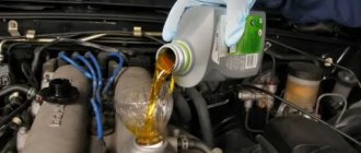
Soviet-made cars are easy to operate and maintain. You can repair a VAZ 2105 yourself in the garage. We are not talking about a major overhaul, but about adjusting and repairing some problems.
Classic "Zhiguli" five, white.
VAZ 2105 is a Soviet small class model. The five first appeared in 1980. The last car, model 2105, rolled off the assembly line in September 2012.
The VAZ 2105 was created on the basis of the Italian Fiat 124 produced in 1966.
The second name of the VAZ 2105 is “Zhiguli” five. After the collapse of the USSR, the model was renamed Lada 2105.
VAZ 2105 was presented in a large number of modifications. Manufacturers produced versions of the model for security services and for participation in rallies.
Engine
Manufacturers offered two engine options:
- 1.5-liter power unit with a power of 72 hp. With.;
- 1.3-liter power unit producing 64 hp. With.
Export VAZ 2105 cars were equipped with a 1.3-liter engine. For the domestic market, manufacturers produced a model only with a 1.5-liter power unit.
The engine inherited the cylinder block from the VAZ-2101. Manufacturers abandoned the use of a chain and equipped the engine with a camshaft belt drive. The modification reduced the noise of the power unit. But it did not completely eliminate the problem.
VAZ-2105i, VAZ-2104i operation, maintenance and repair manual
The VAZ-2105 car is a five-seater, four-door, with a sedan-type monocoque body, and is the second basic model of rear-wheel drive VAZ cars. It appeared as a result of a deep restyling of the first basic model of the VAZ-2101. The main difference between the VAZ-2105 and previous VAZ models of the “classic” layout is aluminum bumpers with rubber linings, original high-back front seats, a more modern instrument panel, original design of the radiator lining, modified shape of the wings, hood and trunk lid, block headlights modern design and new larger rear lights. The VAZ-2104 car is a five-seater, five-door, with a monocoque body type station wagon, created on the basis of the VAZ-2105 car and differs from it in the shape of the rear body, the design of the rear seat, the original shape of the rear lights and the reinforced springs of the rear suspension. Both vehicles are designed for use on public roads with hard surfaces. Currently, cars of the family are equipped with a carburetor engine of the VAZ-2103 model with a displacement of 1.5 liters or an injection engine of the VAZ-2104 model. The latter was created on the basis of the VAZ-2103 engine, complies with Euro-2 toxicity standards and, with better fuel efficiency, ensures virtually unchanged dynamic qualities of the car. At the beginning of production, the cars were equipped with a VAZ-2105 model engine specially developed for this family with a displacement of 1.5 liters, with belt drives of the gas distribution mechanism and improved power characteristics. However, due to production reasons, this engine was completely discontinued, so it is not described in this book. A five-speed gearbox is currently installed on VAZ-2105, VAZ-2104 cars and their modifications. In the first years of production, along with a five-speed gearbox, cars were also equipped with a four-speed gearbox. The main gear installed in the driving rear axle is single-stage hypoid. For production reasons, vehicles can be equipped with final drives with different ratios (3.9 or 4.1). The differential, mounted in a common housing with the main gear, is gear-type, bevel, two-satellite. The front suspension is independent, lever-spring, with hydraulic shock absorbers and anti-roll bar. The rear suspension is dependent, spring, with hydraulic shock absorbers. The steering column is injury-proof, equipped with cardan joints and joints and an anti-theft device built into the ignition switch (lock). The braking system is dual-circuit, with disc brakes on the front wheels and drum brakes on the rear wheels. To increase the level of passive safety of the driver and passenger in the front seat and for the outer passengers in the rear seat, seat belts with inertia reels are provided, and for the middle passenger in the rear seat there is a lap belt. Heating of the cabin is provided by a flow of air heated by the liquid of the engine cooling system.
TRANSMISSION Design features The vehicle can be equipped with a four-speed or five-speed gearbox. The five-speed transmission is based on the four-speed unit, so both units are interchangeable and have most of the same parts. Since the manufacturer installs only five-speed gearboxes on cars of recent years of production and they are gradually replacing four-speed gearboxes, this book discusses the repair of a five-speed gearbox as more complex. The gearbox consists of a primary II, secondary 27 and intermediate 5 shafts, a crankcase 16 and a gear shift mechanism. The input shaft II is made integral with the gear 18 of constant mesh. It rotates on two ball bearings, the front one is pressed into the socket of the crankshaft end, the rear bearing 14 is placed in the gearbox housing and sealed with an oil seal 13. The secondary shaft 27 is installed in three bearings. The front needle bearing 19 is installed in the bore of the input shaft; middle bearing 30 - ball, pressed into the housing housing 16 of the gearbox; the rear bearing 46, located in the socket of the rear cover 49, is sealed with an oil seal 41. On the secondary shaft, gear 28 of the 1st gear, gear 25 of the 2nd gear, and gear 24 of the 3rd gear are freely located; they are in constant mesh with the intermediate shaft gears of the same name. At the front end of the secondary shaft there are three splines on which the hub of the sliding clutch 21 for the third and fourth gear synchronizer is located. The hub 26 of the sliding clutch of 1st and 2nd gears is connected to the shaft in a similar way. Reverse gear 31 is secured to the shaft with a key. The drive gear 47 of the speedometer drive is located on the rear journal of the shaft. The flange 42 of the elastic coupling of the propeller shaft is put on the shaft splines and secured with a nut 43. The intermediate shaft 5 is made integral with the gear block and rests on two bearings; front bearing 6 is ball, fixed on the shaft with washer 8 and bolt 7, rear bearing is roller, cylindrical. The reverse gear 52 is located on the shaft splines. The reverse intermediate gear 51 rotates freely on an axis 53, pressed into the holes of the box housing and its rear cover 49. The synchronizers for all gears have the same design. Each of them consists of a hub 26, a coupling 21, blocking rings 22 and springs 23. The hub is rigidly connected to the secondary shaft. A sliding clutch is located on the outer splines of the hub. The locking ring, with its inner rim, is connected to the synchronizer rim of the gear of any forward gear and is constantly pressed towards the sliding clutch. Gear shifting is carried out using a mechanical drive consisting of three rods 16, 17, 18, on which forks 14, 15, 1 are attached, which fit into the recesses of the sliding clutches of the forward gear synchronizers. Fork 1 enters the annular point of the reverse intermediate gear. In the neutral and engaged position, the rod is held by ball clamps and 23, and the simultaneous engagement of two gears is prevented by nuts 19. The gear shift lever is composite, its lower part is connected to the upper part through a damper device (items 9, 10, 11, 12). This connection allows you to remove the gearbox from the car without “unnecessary” disassembly. The gear shift lever with its head is placed in the ball support 4 and is pressed against it by a spring 7 through a spherical washer 6. Rotation of the lever is prevented by a pin that fits into the hole of the lever and support 4. The design of the five-speed gearbox is basically the same. The difference is in the modified rear cover, in which the synchronizer hub 47 and the 5th gear driven gear are installed on the extended secondary shaft 18 (see figure); In addition, a block 46 of fifth gear and reverse gears is attached to the modified intermediate shaft 55. The gear shift mechanism has a slightly modified design.
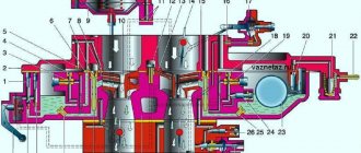
Four-speed gearbox design: 1 - bottom cover; 2 — hole plug for checking the oil level; 3 — gear II of the intermediate shaft; 4 — gear III gear of the intermediate shaft; 5 — intermediate shaft (gear block); 6 — front bearing of the intermediate shaft; 7 — clamping washer bolt; 8 — clamping washer of the front bearing about the intermediate shaft; 9 — constant mesh gear of the intermediate shaft; 10 — thrust washer for the 4th gear synchronizer spring and the input shaft; 11 — input shaft: 12 — front cover; 13 — input shaft oil seal; 14 — rear bearing of the input shaft; 15 — clutch housing: 16 — gearbox housing: 17 — breather; 18 — constant mesh gear of the input shaft; 19 — needle bearing of the front end of the secondary shaft; 20 — gear ring of the 4th gear synchronizer: 21 — sliding clutch of the 4th and 3rd gear synchronizer; 22 — blocking ring of the third gear synchronizer; 23 — third gear synchronizer spring; 24 — gear of the 3rd gear and secondary shaft: 25 — gear of the 2nd gear of the secondary shaft; 26 — hub of the sliding clutch for the synchronizer of 1st and 2nd gears; 27 - secondary shaft; 28 — gear 1st gear and secondary shaft; 29 — bushing of the secondary shaft transmission gear; 30 — intermediate bearing of the secondary shaft; 31 — secondary shaft reverse gear; 32 — gear shift lever rod; 33 - thrust pad; 34 - elastic bushing; 35 — spacer sleeve; 36 — locking sleeve; 37 — outer cover of the gear shift lever; 38 — inner cover of the gear shift lever; 39 — spherical washer of the ball joint of the lever; 40 — gear shift lever; 41 — oil seal of the rear bearing of the secondary shaft; 42 — flange of the elastic coupling of the cardan shaft; 43 — nut of the rear end of the secondary shaft; 44 — seal: 45 — centering ring of the elastic coupling of the cardan shaft; 46 — rear bearing of the secondary shaft; 47 — speedometer drive gear; 48 — speedometer drive; 49 — rear cover of the gearbox; 50 — reverse fork; 51 — reverse intermediate gear; 52 — reverse gear of the intermediate shaft; 53 — axis of the reverse intermediate gear; 54 — gear 1 of the intermediate shaft; 55 - magnet; 56 - magnetic plug. Design of a five-speed gearbox We bring to your attention a manual for the repair and operation of VAZ-2105 and VAZ-2104 cars equipped with carburetor and injection engines. All sections devoted to the maintenance and repair of units and systems contain lists of possible faults and recommendations for their elimination in the form of tables. Instructions for disassembling, assembling, adjusting and repairing vehicle components and systems using ready-made spare parts and assemblies are given operationally and illustrated with photographs and graphic drawings. Moreover, the technology of work was chosen in relation to the conditions of the garage using a universal tool, and only in exceptional cases recommendations were given for the use of special tools available for free sale.
The repair operations of units and components in each section are selected according to the principle “From simple to complex”: starting with the simplest maintenance operations, adjusting units and systems, replacing their individual, often failing parts, with a gradual transition to major repairs of units. Photographic materials were prepared during the process of disassembling and assembling cars by highly qualified auto mechanics. Descriptions of repair operations include useful tips from the practice of experienced motorists. In addition, in the book you will find the following: - in the “Car Structure” section you will find general information about the car and its passport data. The lock keys supplied to the car are described in detail; controls and instruments located on the instrument panel; techniques for controlling heating and ventilation of the cabin, using seat belts and elements of cabin equipment, adjusting the position of seats and controlling the transmission; — the “Operating Recommendations” section contains advice on what you need to have in your car during everyday use and on long trips, how to prepare the car for departure, run it in and operate it during the warranty period. In order to be able to act according to plan when servicing a car independently or to monitor the progress of work when servicing at a service station, the table “Maintenance Schedule” is provided, which includes a list and timing of inspection and routine maintenance. In the subsection “Preparation for departure”, in detail, taking into account a novice driver, photographs show the processes of checking and preparing vehicle systems. In addition, recommendations are given on traffic safety and safety precautions when carrying out repair work on a car. Techniques for refueling a car, using a jack and towing a car are described; — in the “Faults on the Road” section, the experience of many generations of motorists is summarized, which will help eliminate almost any sudden car malfunction. Moreover, the troubleshooting procedure is illustrated with photographs; — in the “Electrical Equipment” section, in addition to the general diagram of electrical equipment, functional diagrams for connecting devices and systems are given, which facilitates troubleshooting; — the appendices contain all the information necessary for operation, maintenance and repair on the tightening torques of threaded connections, operating materials and liquids, filling volumes and masses of the main units, on lamps and spark plugs used on the vehicle, and basic data for adjustment and control. The structure of the book is designed in such a way that photographs or drawings without a serial number are a graphic addition to subsequent paragraphs. When describing work that includes intermediate operations, the latter are indicated as links to the subsection and page where this operation is described in detail. The book can be useful to all motorists who carry out car repairs of any complexity on their own.
Tuning
Lada 2105 in tuning.
Do you recognize? Fans of the domestic automobile industry tune the VAZ 2105. They fix factory faults and change the appearance using body kits, painting the car, and installing lighting.
Technical tuning can be done without a service station. The pistons and clutch are being replaced, and the gear ratio in the box is being selected. You can also increase the stiffness of the suspension by replacing the damping springs and levers.
After changes in the technical parameters of the VAZ-2105, it is necessary to modify the car’s braking system - update the brake pads and rear calipers.
VAZ 21043 engine do-it-yourself repair
If you are the owner of a VAZ 21043 car, then you probably have had to deal with repairs more than once. Unfortunately, all domestically produced cars, especially those that are not at all young, break down quite often and their owners have to repair the car either with their own or take it to a workshop. In most cases, repairs of VAZ 21043 cars are done with your own hands, because the owners of these cars usually do not have the opportunity to send their iron friends to workshops for repairs.
If you own such a car and are going to repair it only with your own efforts, then you just need to know what breakdowns happen most often and how to fix them, as well as what to do to ensure that they occur as rarely as possible. First of all, you need to modify the electrics of your car, for this you can install a windshield wiper pause relay from a VAZ 2108 car, it will work longer and more efficiently compared to the standard one, and will also allow you to adjust the pause between wiper sweeps. It would be a good idea to install headlight cleaners on your car, which can keep the headlights clean in any weather, improving road illumination and making driving safer.
After finalizing the car's electrics, you can slowly move on to the engine, which also really needs it. First of all, it will be necessary to install a single-row chain on the VAZ 21043 engine, instead of a double-row one, which will allow for quieter operation and add a little more dynamics. If you want to make your old lady even more convenient in terms of changing gears, then you can think about installing a Fiat gearbox, but this will be a more serious modernization that will require considerable financial investments. Replacing the standard gearbox with a 5-speed one from Fiat will increase the speed of the car and make it more economical. Of course, you can also install a VAZ 5-speed gearbox, but it will be less reliable and quite expensive.
Car pump device
In case of many defects, the pump is replaced on a VAZ sixth model, a video about which can always be watched on the Internet. The “six” prefers to change the entire water pump, because Many car enthusiasts do not repair this component of the car cooling system due to its low price when purchased at a spare parts store. The price of a “six” water pump in various retail outlets is quite reasonable, varying from 600 to 700 rubles.
The liquid base (antifreeze) acts as a cooler for the power plant, which heats up during operation. But the cooler is moved using the so-called. “pump” (water pump), which with its impeller blades forces liquid to flow into the supplied pipes. When the “six” water pump is not working, the temperature of the engine begins to steadily increase, which can lead to its overheating, deformation of individual elements and subsequent breakdown. Therefore, it is necessary to replace the pump or repair it. What the water pump consists of can be seen when replacing the oil seal of the VAZ 2106 pump: it is a pump of a centrifugal operating principle, to which the rotational torque is transmitted from the crankshaft pulley of the vehicle’s engine unit. The part is located on the right side of the “engine” and is mounted with a paronite gasket. The product is cast from light aluminum alloys, the shaft of which is equipped with a double-row non-separable bearing without a cage. At one end of the shaft there is a blade impeller, at the other end there is a pulley hub.
An O-ring with the help of an oil seal forces the impeller to be in a state of readiness for operation. Under the action of the rotating impeller, the required pressure is created, with the help of which antifreeze is pumped into the cooling system and supplied to cool the power plant and other components of the vehicle.
All components of the water pump can be seen when replacing the pump seal, which is carried out during plumbing repairs. To find out whether the coolant is circulating in the heating system and whether the “six” pump is functioning, we perform the following simple steps: start and heat the engine to an operating temperature of 90 degrees Celsius and squeeze the upper pipe directed to the radiator with both hands. If the water pump is functioning, you will feel the circulation of antifreeze in the system.
Stages of setting up a VAZ 2015 carburetor
Without knowing the design of the car and without any experience in repairing, disassembling or assembling the fuel system of a car, it is not recommended to make adjustments. Changing the settings incorrectly may worsen the problem or damage the device. If you are familiar with the design of your car's carburetor, adjusting it will not be difficult. Adjusting the 2105 carburetor can significantly improve vehicle efficiency, reduce fuel consumption and increase the performance of the power unit. These so-called performance upgrades do not have any detrimental effect on the device. On the contrary, they are a mandatory procedure that guarantees long, uninterrupted operation.
Screws for adjusting the idle speed system of the VAZ 2105 carburetor: 1 - mixture quantity screw; 2 - mixture quality screw
Crankshaft speed calibration. The first thing to do is change the speed to 750-800 units per minute. To perform this procedure, a quantity adjustment screw is provided. It must be screwed all the way, and then unscrewed three times in the opposite direction.
Change in CO2 content. We regulate the amount of carbon dioxide in the exhaust using the quality screw. To do this, you need to screw the screw in until it stops, and then unscrew it back 4-5 turns. This will increase the concentration of fuel and richen the mixture.
Warming up the engine is a mandatory procedure, without which you cannot proceed to the next stages of work.
Speed adjustment. Using the quantity screw, we adjust the idle speed. It is necessary to achieve stable operation of the motor at 750-800 rpm. Gradually tightening the quality screw. During this process, the speed should increase slightly and then decrease, causing the engine to run erratically. After unstable operation of the power unit begins, we begin to screw the screw back in until the operation of the motor stabilizes.
Setting XX. Finally, you need to calibrate the idle speed using the appropriate screw to 800-900 units.
After completing all stages of adjustment and achieving the required parameters, you need to test the carburetor. With the engine running, sharply press the accelerator pedal and release it. If adjusted correctly, the crankshaft speed will temporarily increase. If the engine stalls, increase the speed using the appropriate adjusting screw. Check the operation of the motor at full load by turning on the stove, lights, etc.
Idle speed solenoid valve
The carburetor idle speed control valve controls the idle speed of the engine. People often ask why I change or remove the wire from the solenoid valve, but the idle speed works. It’s simple, it means the carburetor idle system is clogged, the engine maintains idle speed thanks to the tightened bolt 3 in the photo above. Usually when the idle system is clogged, but the engine is running, taking fuel for idle from the main carburetor system, or the idle system is not clogged and bolts 1 and 2 are tightened. Usually the engine running at idle, taking fuel from the main carburetor system, does not hold idle speed well, they then increase, then decrease.
It also happens that the idle speeds disappear, usually an unknowing driver increases the idle speeds, and it turns out that the idle speeds start working from the main carburetor system.
Expert advice
After completing the procedure for adjusting the VAZ-2105 carburetor device, experienced auto mechanics recommend paying attention to the following critical points:
- Valve location - is in the retracted position, with the idle speed jet touching the seat in the carburetor body.
- Lubricating the rubber seal with special motor oil.
- The location of the air damper intended for cold passage is in a vertical plane, while the suction handle is lowered.
- The condition of the solenoid valve - the presence of damage and malfunctions is checked as follows:
- turn on the ignition;
- remove and put the connector on the valve;
- listen to the sounds coming from the solenoid valve.
If clicks are heard during the inspection process, the part is in full working order.
Signs of a malfunction of the VAZ 2107 crankshaft position sensor
- The first thing that may indicate the imminent death of the crankshaft sensor is an arbitrary decrease or increase in engine idle speed.
- Severe reduction in engine power
- Unable to start the engine
Removing the crankshaft position sensor
- Disconnect the contact chip from the sensor by first releasing the latch
- Using a Phillips screwdriver, unscrew the sensor mounting screw.
- After removing the crankshaft position sensor, check its operation using a multimeter
Checking the crankshaft position sensor VAZ 2107
Sources
- https://avtozam.com/vaz/2107/snyatie-shkiva-kolenvala/
- https://remont-vaz2106.ru/vaz-2105-snyatie-kolenchatogo-vala
- https://remontauto-vaz.ru/page/diagnostika-i-zamena-datchika-polozhenija-kolenvala-vaz-2107
What does a pump do on a car?
The cooling pump is mounted closer to the front of the cylinder block, and the torque is transmitted by the generator belt. The element solves the function of constant supply of coolant (coolant), which significantly increases the effect of heat removal from the engine.
The part consists of a housing, a shaft with an impeller, a sealed seal and bearings. As a rule, the housing and impeller are made of aluminum or magnesium alloy. As for the impeller, it is made of plastic.
If we keep in mind the design diagram, then the VAZ classic pump consists of two halves: one does not contain any moving elements and is permanently attached to the cylinder block, the other includes moving parts, such as an impeller and bearings.
Bearings ensure the rotation of the shaft. The housing has special channels for supplying and discharging liquid. The impeller rotates, a centrifugal force arises, which throws the coolant towards the outer walls of the housing. Thus, pressure is created, forcing the liquid into a specially designed tube located in the cylinder block (cylinder block). Making a large circle (circulation), the liquid again enters the pump through the lower pipe.
Pump design in the engine cooling system
Due to this precise sequence and fluid circulation effect, the hottest engine elements are cooled.
As mentioned above, the detail on the classic has some features. Due to the fact that the pump consists of two parts, when replacing, many people confuse the front cover with a full-fledged pump. In fact, the name water pump refers to the entire assembly, which also includes pipes.
A sealed gasket is installed between the cover and the pump body to protect against leaks. During the replacement process, it should also be updated.
Expert advice
After completing the procedure for adjusting the VAZ-2105 carburetor device, experienced auto mechanics recommend paying attention to the following critical points:
- Valve location - is in the retracted position, with the idle speed jet touching the seat in the carburetor body.
- Lubricating the rubber seal with special motor oil.
- The location of the air damper intended for cold passage is in a vertical plane, while the suction handle is lowered.
- The condition of the solenoid valve - the presence of damage and malfunctions is checked as follows:
- turn on the ignition;
- remove and put the connector on the valve;
- listen to the sounds coming from the solenoid valve.
Models 2105 and 21053: technical specifications
This valve needs to be washed; it is strictly forbidden to do this with plain water. Solvent is the most convenient, high-quality and common means for flushing the valve. Then be sure to dry it with compressed air. If the engine does not perform as well as usual during operation, or your car responds slowly or does not respond at all to pedal inputs, then the strainer is most likely the cause of the problem.
Engine of a car of this model
The float chamber also needs cleaning
It is very important not to wipe its bottom with a lint rag, since the lint remaining on the bottom will clog the mechanism jets. To effectively clean the float chamber, you need to use a blower made of rubber, and you need to dry it in the same way as a mesh filter - with compressed air
VAZ 2105
After many years of carburetor life, the “five” eventually acquired first central and then distributed injection, which only benefited it. Domestic control systems have already gotten rid of childhood ailments, and in general, modern modifications of VAZ engines have proven to be more reliable than carburetor “retrogrades”. And they are more pleasant to use - they pick up better from the bottom, and do not twitch immediately after starting. Engine driven attachments may require unexpectedly early and sudden intervention. The fact that foreign cars run hundreds of thousands of kilometers, burns out in dozens on a VAZ “classic”. Water pump, generator, starter (as, indeed, almost all electrical equipment), etc. They will require a “wagon of attention” after a year or two of operation. And at the most unexpected moment.
VAZ 2105 injector diagram
1 – electric motor of the engine cooling system fan; 2 – mounting block; 3 – idle speed regulator; 4 – electronic control unit; 5 – octane potentiometer; 6 – spark plugs; 7 – ignition module; 8 – crankshaft position sensor; 9 – electric fuel pump with fuel level sensor; 10 – tachometer 2105; 11 – control lamp “CHECK ENGINE”; 12 – car ignition relay; 13 – speed sensor; 14 – diagnostic block; 15 – nozzle; 16 – adsorber purge valve; 17, 18, 19 – injection system fuses; 20 – ignition relay for the injection system; 21 – relay for turning on the electric fuel pump; 22 – intake pipe electric heater relay; 23 – electric heater of the intake pipe; 24 – intake pipe heater fuse; 25 – oxygen concentration sensor; 26 – coolant temperature sensor; 27 – throttle position sensor; 28 – air temperature sensor; 29 – absolute pressure sensor;
- A – to the “plus” terminal of the battery;
- B – to terminal “15” of the ignition switch;
- P4 – relay for turning on the fan motor.
Setting the carburetor choke
How much trouble does incorrect carburetor choke adjustment bring to drivers, especially in winter. In some cars, you pull the choke all the way, but the engine does not hold speed, you have to hold the gas pedal until it warms up. For others, on the contrary, you pull the choke all the way, and the engine screams like crazy, although during warm-up such high engine speeds are unnecessary.
Photo. Carburetor suction system.
The whole point is that the lever for forced opening of the carburetor throttle valve is incorrectly adjusted when the choke is pulled.
All this is easy to fix; in the photo above the arrow shows the thrust for forced opening of the throttle valve at the moment the choke is pulled out. If the engine does not hold speed, then it is possible that the rod is on the lower hole of the throttle lever; the photo shows two holes for the throttle rod. Move the rod into the upper hole of the lever.
If the engine is spinning very quickly on the choke, then use pliers to slightly bend the rod shown by the arrow; it bends easily without removing it from the carburetor; if the engine speed is low, straighten this rod. In this way, you can easily adjust the desired engine speed when starting on choke.
Setting the choke engine speed in a VAZ 2108 carburetor is even simpler; the photo above shows boot 3; by tightening it, the choke engine speed will increase, and unscrewing it will decrease.
I hope that after reading this article, you can easily adjust the carburetor on your car yourself.