The brake system is an important link in a car, as it is primarily responsible for traffic safety and, ultimately, for the life and health of road users. Therefore, its maintenance should be taken very seriously, strictly and promptly follow all the manufacturer’s recommendations. This section includes a fairly wide range of materials. All procedures for replacing pads, cylinders, discs and many other parts of the brake system are described in detail and clearly. Many articles contain not only original information on do-it-yourself repairs, but also include special information blocks with useful tips to make life easier when performing a particular job.
I think there is no need to explain once again that due to poor lubrication of the caliper fingers, certain problems can arise, for example: unevenness.
In this article I will try to talk about such a procedure as replacing the parking brake cables on a Lada Kalina car. For starters, it's worth it.
Yesterday my friend arrived, for whom we recently bought a Kalina sedan. So, his problem was the following: from.
From the first months of using my Kalina, I wrote on this blog about a problem with the brake fluid level sensor. On the panel.
One of the reasons why the brake lights on your Kalina may not work is a failure of the switch or something like that.
Adjusting the handbrake on Kalina involves either tensioning or loosening the cable. In most cases, it is necessary to do the tension, just like that.
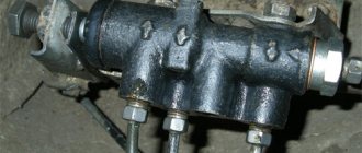
Judging by user requests, Kalina owners practically do not experience any breakdowns related to the front brake wheel cylinder. May with.
Before you begin this repair, you first need to measure the thickness of the brake rotor. If it is less than 17.8 mm, then.
Typically, brake cylinders last quite a long time and do not require replacement, but during long-term use a situation may arise where the internal ones.
As you know, rear brake pads do not wear out as much and do not have to be replaced as often as the front ones. But if.
To remove the rear brake drum on Kalina, we will need no more than 20 minutes of time and the tools listed below: Jack.
About a month ago I wrote a topic in which I shared the problem I had with the front brake pads. The essence of this malfunction was as follows.
A couple of days ago the following problem arose: when braking, especially when braking sharply, a strong creaking noise began to appear from the front left wheel.
After a short run of my Kalina, after about 12,000 km, the brake fluid level lamp started flashing, and I got a little worried.
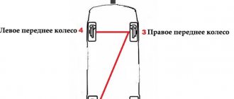
One of the most popular domestic cars is the VAZ 1118 Kalina, which our citizens have come to love for its ease of use, reliability and efficiency. The Kalina brake system has two operating circuits located diagonally. The right front wheel is connected to the rear left, and the front left, respectively, to the rear right. This design ensures safety during vehicle operation and also reduces the likelihood of brake failure.
Working brake system: 1 — brake mechanism of the front left wheel; 2, 6, 12, 17 — brake hoses; 3, 7, 11, 18 — brake pipes; 4 — main brake cylinder; 5 — brake mechanism of the front right wheel; 8 — reservoir of the main brake cylinder; 9 — vac>smart amplifier; 10 — brake pedal; 13 — brake mechanism of the rear right wheel; 14 — fluid pressure regulator in the brake mechanisms of the rear wheels; 15 — lever for regulating the fluid pressure in the brake mechanisms of the rear wheels; 16 — brake mechanism of the rear left wheel Note. Some cars are equipped with a braking system with ABS (anti-lock braking system).
The brake system of the Lada Kalina car
The hydraulic brake system of a VAZ 1118 car consists of a pedal lever, a hydraulic master cylinder, a vacuum brake booster 1118, a hydraulic reservoir, a pressure regulator, a regulator drive lever, pipelines, flexible reinforced rubber hoses, tees, and fastening clamps. At the same time, the brakes on this VAZ model can be equipped with an anti-lock braking system, but it was not installed in the first series of Kalina production. Today, almost the entire line of cars comes with an ABS system.
Vacuum booster on a VAZ 2170 2171 2172 Lada Priora: 1 - tip mounting flange; 2 — rod; 3 — diaphragm return spring; 4 — sealing ring of the master cylinder flange; 5 - main cylinder; 6 — amplifier pin; 7 — amplifier housing; 8 - diaphragm; 9 — amplifier housing cover; 10 - piston; 11 — protective cover of the valve body; 12 — pusher; 13 — pusher return spring; 14 — valve spring; 15 - valve; 16 — rod buffer; 17 — valve body; A - vacuum chamber; B - atmospheric chamber; C, D - channels
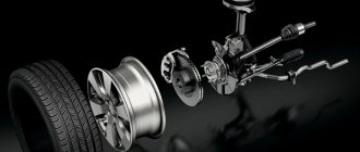
Features of the front wheel braking system
The front wheels of the VAZ 1118 are equipped with a ventilated disc system with a piston floating caliper. It includes a wheel cylinder and a caliper, which are tightened together with special screws. The cylinder itself is attached to the guide pins with two bolts installed in the guide block (holes). The pads are pressed against the guide grooves by springs. Inside the cylinder there is a piston with a sealing ring having a rectangular cross-section. The elasticity of the ring provides an optimal gap between the disc and the brake pads, which ensures high-quality functioning of the system.
How to properly bleed the brakes
Before starting work, you should make sure that you have the necessary materials and tools that should be on hand:
- brake fluid;
- wrench “8” (socket or open-end) to loosen the fittings;
- elastic hose suitable for a tight fitting on the fitting;
- a suitable container for receiving used brake fluid;
- slotted screwdriver;
- wheel chocks;
- lift, inspection pit or overpass.
A partner, sitting in the cabin, will press the brake on command.
Sequencing
Hang the car on a lift or secure it with wheel chocks on a viewing hole or overpass. Wheel bleeding procedure:
- Rear right wheel.
- Front left wheel.
- Rear left wheel.
- Front right wheel.
The algorithm of actions performed is the same for all four wheels.
Leveling procedure
Bleeding the Kalina brake system will require you to first take the following preparatory steps:
- Open the electrical circuit of the low brake fluid level indicator sensor in the expansion tank.
- Unscrew the cap and remove it together with the float, freeing the neck to quickly replenish the volume of fluid in the braking system during adjustment.
- Make sure that the level is above the MIN mark, top up if necessary.
- Check that the pressure regulator valve is set correctly (otherwise it will not be possible to bleed the rear wheels).
Self-bleeding brakes
In the future, you cannot do without an assistant who, sitting in the driver’s seat, will operate the brake pedal according to the commands of a partner located under the bottom of the car. The procedure for pumping wheels on Kalina is as follows:
- The protective cap is removed from the fitting and its tip is covered with an elastic tube. The mating part of the tube is placed in a suitable container.
- Using a ring wrench “8” with a slot, the swivel nut of the fitting is covered.
- The person in the cabin, upon command, presses the brake pedal all the way with successive movements and holds it close to the floor.
- A partner under the car unscrews the fitting counterclockwise and, after waiting for the brake fluid to stop leaking, closes it again.
The last two steps are repeated until air bubbles stop appearing in the liquid. Having put the safety cap on the screwed fitting, they begin to work with the next wheel according to the scheme.
Fluid control
Constantly monitoring the level of brake fluid in the expansion tank above the minimum mark will help eliminate the occurrence of air locks in the system.
Main problems with the brake system of the VAZ 1118 Kalina
Everyone understands the importance of this system in a car, and therefore timely maintenance can significantly improve safety and also prevent accidents. At the same time, during intensive use, as well as the specificity and quality of the components in the mechanism, some of its elements may fail ahead of schedule.
That is why you should constantly monitor its condition, and also pay attention to possible malfunctions.
- Air in the brake system. To solve the problem, you need to “bleed” the system, which can be done both in a garage and at a service station.
- Brake fluid leak. Worn pipelines and rubber hoses
- Increased pedal travel. The vacuum booster is faulty; the hose needs to be replaced or its attachment to the fittings checked.
- Low braking efficiency. It is possible that the brake linings become oily, the pistons in the cylinders become jammed, the linings wear out, or the regulator is adjusted incorrectly.
- The car pulls to the side during braking. Different tire pressures, wheel camber/toe angles are incorrect, disks or drums are dirty or oily.
- Brake vibration or squeaking. Weakening of the tension spring, wear of the linings, oiling of the friction linings.
Features of the brake system of the Lada Kalina Sport
Lada Kalina Sport is an improved version of the domestic car, which has higher speed characteristics. As for the brakes, they have been qualitatively improved - the rear drum units have been replaced with disc ones.
In general, the Kalina Sport brake system is more reliable, since it is designed for high loads and speeds higher than usual. In addition, an ABS anti-lock braking system is installed here, which provides additional protection against skidding.
Repair
For repairs, you need a garage, the ability to hang the car, a set of tools, knowledge and skills in troubleshooting typical faults in the brake system of Kalina and other cars. If you have all this, you can repair it yourself, but if not, it’s better to contact a car service center, where they will do a high-quality restoration for little money. If the car is under warranty, it is especially not worth repairing it yourself.
Source
To perform the work, you will need a special wrench for the brake pipe fittings.
1. We prepare the car for work.
2. We clean the connections of the brake hose tips and pipes from dirt and corrosion. We treat the tube fittings with penetrating lubricant.
Warning!
When performing the following operation, make sure that when unscrewing the fitting, the tube does not rotate with it. If the tube is “sour” in the fitting, replace it.
3. While holding the upper end of the hose from turning with a 15 mm open-end wrench, use a special wrench to loosen the tightness of the tube fitting.
4. We finally unscrew the fitting with a 10 mm open-end wrench.
5. To prevent brake fluid leakage, place a protective cap on the end of the brake pipe for the working cylinder bleeder fitting.
6. We remove the upper tip of the brake hose from the hole in the body bracket.
7. In the same way, unscrew the tube from the lower tip of the brake hose and release it, leading it out of the hole in the bracket mounted on the rear axle beam.
8. Remove the hose from the car.
1. Install the hose in reverse order.
2. We remove air from the brake hydraulic drive and check the connections of the brake hose and pipes for leaks.
Source
Features of front and rear wheel brakes
The bolts are placed in the passages of the guide blocks, pressed by the guide spring grooves. A piston with a sealing ring of rectangular cross-section is placed inside the cylinder. This ring provides the most rational distance between the disc and the brake pads. This organization of Kalina's braking system contributes to its efficient functioning.
In addition to the head system, the developers equipped the Lada with a mechanical parking brake, which is driven by the brake mechanisms of the rear wheels.
- adjusting rod;
- lever arm;
- two cables;
- equalizer;
- spacer bars;
- pad drive levers.
General checks
Brake Line Connections
Check the condition of the service brake system and parking brake components.
Brake Line Connections
Leakage of brake fluid in connections and hydraulic drive is not allowed.
Parking brake tensioner locknut
The full travel of the parking brake lever should be 2-4 teeth of the sector ratchet device, adjust if necessary:
Move the parking brake lever to its lowest position, loosen the locknut of the tensioning device and, by tightening the adjusting nut, tighten the cable so that the stroke of the lever along the sector ratchet device is 2-4 teeth (clicks).
Checks while driving
Check the effectiveness of the service and parking brakes.
Check the operation of the vacuum brake booster. With the engine not running, press the brake pedal 5-6 times, holding the pedal pressed, and start the engine. If the amplifier is working properly, the pedal should “move forward” after starting the engine. If the pedal does not “go forward”, it is necessary to check the attachment of the tip, the condition and fastening of the vacuum booster vacuum hose, and if necessary, tighten the tip and hose clamp.
Principle of operation
The operating principle of the Lada brake system is as follows. After pressing the brake pedal, the piston begins to move in the cylinder. Fluid from the main exhaust valve enters the Kalina brake system through hydromechanical hoses. The fluid is then directed towards the main wheel mechanism through pipelines, creating the necessary conditions for the movement of the pads to the front wheel disks and to the rear drums. Contact occurs and braking occurs.
- Presence of air in the system. You can solve the problem not only with service, but also yourself. To do this, you need to bleed the brakes.
- Brake fluid leaking. This situation indicates a malfunction of pipelines and rubber hoses.
- Increasing pedal stroke. The problem that has arisen indicates a problem with the vacuum booster. It is recommended to replace the hose and check its attachment points.
- Reduced braking efficiency. In this case, the reason may be oily brake linings, jammed cylinder pistons, compromised gasket integrity, or defective adjustment by the regulator.
- Squeaking or vibration when braking. Perhaps the tension spring is weakened, the linings are out of order, or the rubbing linings are oily.
Service
Maintenance consists of inspecting all components and replacing them in case of wear. All service looks like this:
- checking the brake pedal travel;
- checking and possible adjustment of the parking brake (Kalina has a handbrake from “nine”, so it must be tightened often);
- inspection of all tubes and hoses;
- inspection of the condition of brake discs, drums and pads;
- checking the brake fluid level and replacing it approximately every 40 thousand kilometers.
Differences in the brake system of Lada Kalina Sport
The use of high-quality spare parts influences many factors. It is recommended to use original factory spare parts. It is better to carry out adjustment and repair work at specialized maintenance points. Functioning brakes guarantee the safety of all road users. Paying attention to your braking system will ensure its longevity. The operation of the machine as a whole depends on this.
The service brake system is hydraulic, dual-circuit (with diagonal separation of the circuits), with a pressure regulator in the hydraulic drive of the brake mechanisms of the rear wheels, a vacuum brake booster and a sensor for insufficient fluid level in the reservoir. In normal mode, when the system is working properly, the brake mechanisms of both circuits operate: right front - left rear and left front - right rear. If one of the circuits fails (depressurizes), the other circuit provides braking to the vehicle, although with less efficiency. The brake pedal is a suspended type, equipped with a return spring. Above the pedal there is a brake signal switch, the contacts of which close when the pedal is pressed. To reduce the force on the brake pedal, a vacuum booster is used, which uses the vacuum in the receiver of a running engine. The vacuum booster is located between the pedal pusher and the main brake cylinder and is attached to the front panel. The brake master cylinder is attached to the vacuum booster housing with two studs. A plastic tank with an insufficient fluid level sensor is inserted into the holes located in the upper part of the cylinder through rubber sealing bushings.
Front wheel brake
: 1—brake disc; 2 — pad guide; 3 - caliper; 4 — brake pads; 5 - cylinder; 6 — protective cap of the bleeder fitting; 7 — screw securing the cylinder to the caliper; 8 — bolt securing the cylinder to the guide pin; 9 — guide pin cover; 10— brake disc shield
The front wheel brake is a ventilated disc with a single-piston floating caliper. The floating front brake caliper includes a caliper and a wheel cylinder, held together by two screws. The cylinder is secured with two bolts to the guide pins installed in the holes of the shoe guide. The brake pads are pressed by springs to the grooves in the pad guide. The cylinder contains a piston with a rectangular rubber sealing ring. Due to the elasticity of this ring, a constant optimal gap between the brake pads and the disc is maintained.
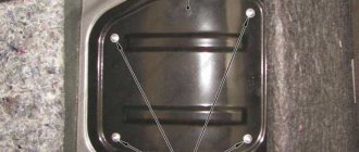
Rear wheel brake
: 1 - lower tension spring; 2 — front block; 3 - guide spring; 4 — spacer bar; 5 - working cylinder; 6 — upper tension spring; 7 — lever for manual drive of the pads; 8 — rear block; 9 — tip of the parking brake cable
The rear wheel brake mechanism is a drum type, with a two-piston wheel cylinder and automatic adjustment of the gap between the shoes and the drum. The automatic clearance adjustment device is located in the wheel cylinder. The main element of the device is a steel split thrust ring mounted on the piston with an axial clearance of 1.25-1.65 mm. The thrust rings (two per cylinder) are inserted into the cylinder with tension, providing a shear force along the cylinder surface of at least 350 N, which exceeds the force of the brake shoe tension springs. When the brake linings wear, the thrust rings shift under the action of the pistons by the amount of wear. If the cylinder mirror is damaged under the influence of mechanical impurities that have entered the brake fluid, or under the influence of corrosion (presence of water in the brake fluid), the rings may “sour” in the cylinder and one or even both pistons will lose mobility. In this case, the cylinders must be replaced. The pressure regulator in the hydraulic drive of the rear wheel brakes is mounted through a bracket in the left rear part of the body. As the load on the rear axle of the vehicle increases, the elastic regulator lever connected to the beam is loaded, transmitting force to the regulator piston. When you press the brake pedal, fluid pressure tends to push the piston outward, which is prevented by the force from the elastic lever. When the system comes into equilibrium, a valve located in the regulator shuts off the flow of fluid to the wheel cylinders of the rear wheel brakes, preventing further growth of braking force on the rear axle and preventing the rear wheels from locking ahead of the front wheels. When the load on the rear axle increases, when the grip of the rear wheels with the road improves, the regulator provides greater fluid pressure in the wheel cylinders, and vice versa - as the load decreases, the pressure drops. The parking brake system is driven mechanically, by cable, to the rear wheels. It consists of a lever, an adjusting rod, an equalizer, two cables, pad drive levers and spacer bars.
Brake system equipment
- Brake pedal. This is a hanging type part. There is a spring return mechanism. Just above the pedal part, the developers placed a brake signal switch.
- Vacuum reinforcement is a part of the diaphragm structure. It is designed to reduce the force exerted by the driver when pressing the brake pedal. It operates due to the difference in pressure in vacuum and atmospheric tanks.
- Fluid pressure regulator. Installed in systems without anti-lock wheels. Serves as a limiter for the flow of fluid towards the rear brakes when the vehicle is partially loaded. This element prevents the wheels from locking and prevents the rear of the vehicle from skidding.
- Brake fluid height sensor. Indicates a drop in liquid height below the minimum value. It is located in a plastic tank, attached through the upper passages of the cylinder using rubber bushings. After the brake fluid level drops below the permissible level, the sensor transmits a signal to the light on the instrument panel.
- Brake signal switches. Their operation is as follows: after pressing the pedal, the electrical contacts close.
- Main brake cylinder. Attached with two studs to the vacuum booster. A reservoir for brake fluid is attached to the base of the brake cylinder.
- Pipelines.
- Regulatory drive lever.
- Elastic reinforced rubber hoses.
- Tees.
- Fastening clamps.