From the point of view of modern environmental requirements, carburetor engines are already outdated. But cars with carburetors feel great on our roads. Yes, they do not correspond to the spirit of the times, but they work conscientiously and will continue to work for a very long time.
That is why the VAZ 2107 carburetor is a very popular unit today. Those who drive a “classic” can service and repair it themselves; there is nothing supernaturally complicated there. On modern foreign cars, stuffed with electronics, do-it-yourself repairs are no longer possible.
Purpose, diagram, structure and principle of operation of the VAZ 2107 carburetor
The “seven” was equipped with various modifications of the DAAZ 2107 carburetor (Dimitrovgrad Automobile Unit Plant). They are all similar in principle and differ only in some design details.
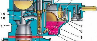
Diagram of the VAZ 2107 carburetor structure: (1 - screw for adjusting the stroke of the accelerator pump intake valve; 2 - carburetor cover; 3 - fuel jet of the transition system of the second chamber; 4 - air jet of the transition system; 5 - air jet of the econostat; 6 - fuel jet of the econostat; 7 — main air jet of the second chamber; 8 — emulsion jet of the econostat; 9 — pneumatic drive of the throttle valve of the second chamber; 10 — small diffuser; 11 — jets; 12 — discharge valve of the accelerator pump; 13 — accelerator pump nozzle; 14 — air damper; 15 - main air jet of the first chamber; 16 - starting device jet; 17 - automatic starting device; 18 - idle air jet; 19 - idle fuel jet; 20 - fuel supply needle valve; 21 - fuel filter; 22 - fuel supply fitting ; 23 — float; 24 — screw for factory adjustment of the idle speed system; 25 — main fuel jet of the first chamber; 26 — adjusting screw for the quality of the working mixture; 27- adjusting screw for the amount of carburetor working mixture 2107-1107010; 28 — throttle valve of the first chamber; 29 — carburetor body; 30 — throttle valve of the second chamber; 31 — throttle body; 32 - emulsion tube; 33 — main fuel jet of the second chamber; 34 — accelerator pump bypass jet; 35 — accelerator pump inlet valve: 36 — accelerator pump drive lever; 37 - carburetor pneumatic valve 2140-1107010-70.)
Purpose.
The purpose of the carburetor is to prepare the gasoline-air mixture in the required proportion and supply it to the engine cylinders. The quality of engine operation, power output, and service life depend on how correctly the ratio between fuel and air is maintained, and how well the dispersion is mixed.
Device and principle of operation. The schematic diagram of the VAZ carburetor is conventionally divided into three structural elements:
- Cover with outlets for hoses;
The structure of the VAZ 2107 carburetor cover: (1 - float axis; 2 - needle valve; 3 - float; 4 - gasket; 5 - trigger diaphragm with rod; 6 - spring; 7 - adjusting screw; 8 - trigger cover; 9 - idle fuel jet; 10 — solenoid shut-off valve; 11 — plug; 12 — carburetor cover; 13 — fuel filter; 14 — air damper; 15 — fuel supply pipe; 16 — air damper axis with lever; 17 — control lever fixation ball air damper; 18 — air damper control lever; 19 — lever axis; 20 — bushing for fastening the air damper drive rod) - The housing in which the float chamber and chambers with diffusers are located;
Structure of the VAZ 2107 carburetor body: (1 - accelerator pump diaphragm; 2 - accelerator pump drive lever; 3 - cover; 4 - accelerator pump drive cam; 5 - power mode economizer cover; 6 - economizer diaphragm; 7 - economizer fuel nozzle; 8 — economizer valve; 9 — check valve of the accelerator pump; 10 — accelerator pump nozzles with a fuel supply valve; 11 — nozzles; 12 — main air jets with emulsion tubes; 13 — main fuel jets; 14 — bracket for fastening the air damper drive rod shell; 15 — adjusting screw of the second chamber; 16 — stopper of the adjusting screw; 17 — stopper cap; 18 — adjusting screw for slightly opening the throttle valve of the first chamber; 19 — axis of the throttle valve of the first chamber with drive levers; 20 — locking lever of the second chamber; 21 — lever spring locks; 22 — throttle axis of the second chamber with a lever; 23 — throttle valve of the first chamber; 24 — throttle valve of the second chamber; 25 — plug for adjusting screw of mixture quality (composition); 26 — return spring of the throttle valve drive lever of the second chamber; 27 — adjusting screw for the quality (composition) of the idle mixture; 28 — carburetor body; 29 — adjusting screw for the amount of idle mixture; 30 - electrical wire of the limit switch of the forced idle economizer; 31 - carburetor heating unit) - The bottom where the throttle valves are located.
Now in more detail about the design and principle of operation:
- Using a fuel pump, gasoline is pumped into the float chamber from the tank to a certain level, which is regulated automatically by opening and closing the needle valve;
- Then fuel is pumped from the float chamber through nozzles into the mixing chambers. In this case, the fuel is already divided into small droplets, which are mixed with the air coming from the air intake with an air filter;
- Econostat is a device for enriching the fuel mixture. It turns on when the engine is running under high load and adds additional fuel to the mixing chambers;
Diagram of the econostat and economizer of the VAZ 2107 carburetor: (1 - throttle valve of the second chamber; 2 - main fuel jet of the second chamber; 3 - fuel channel; 4 - main fuel jet of the first chamber; 5 - throttle valve of the first chamber; 6 - vacuum supply channel; 7 — economizer diaphragm; 8 — ball valve; 9 — economizer fuel jet; 10 — fuel channel; 11 — air damper; 12 — main air jets) - Then the mixture of gasoline and air enters diffusers, where droplets of gasoline are crushed and the resulting mixture is finally mixed;
- The finished mixture enters the fuel (intake) manifold through the throttle valves. The amount of air in the fuel mixture is regulated by an air damper, and the volume of the finished mixture that goes into the fuel manifold is regulated by two throttle valves (one for each chamber);
- At high speeds, the accelerator pump turns on.
Diagram of the VAZ 2107 carburetor accelerator pump (1 - nozzles; 2 - fuel supply ball valve; 3 - pump diaphragm; 4 - pusher; 5 - drive lever; 6 - pump drive cam; 7 - first chamber throttle valve; 8 - check ball valve ; 9 — throttle valve of the second chamber) - A separate idle system is provided, which supplies the minimum required amount of gasoline so that the engine runs smoothly and does not overuse gasoline.
A working carburetor does not need any control. The system itself determines in what mode the engine operates, how much fuel mixture to supply and at what moment. But sometimes it is necessary to carry out maintenance of this unit with tuning and adjustment.
Adjustment and tuning of the VAZ 2107 carburetor. Calibration data.
If signs of a malfunction appear, it is quite possible (and even necessary) to adjust the carburetor of the VAZ 2107 yourself. Adjustment is necessary when problems begin with the mode and quality of engine operation:
- Difficult engine start, the car does not start for a long time;
- Violation of acceleration dynamics, slow, heavy acceleration;
- When you press the gas pedal, dips, malfunctions and jerks in the engine operation appear, the car noticeably jerks when moving;
- Fuel consumption increases for no apparent reason.
Carburetor calibration table 2107-1107010
Idle speed adjustment (XX)
Correctly set idle speed is a guarantee that the carburetor will not make “dips” at the minimum engine operating mode, but will not waste extra fuel.
Diagram of the idle system and transition systems of the VAZ 2107 carburetor: (1 - electromagnetic shut-off valve; 2 - idle fuel jet; 3 - idle air jet; 4 - fuel jet of the second chamber transition system; 5 - air jet of the second chamber transition system; 6 — outlet of the transition system of the second chamber; 7 — main fuel jets; 8 — slit of the transition system of the first chamber; 9 — mixture quality adjusting screw)
- Start the engine, warm it up to standard operating temperature, then remove the choke;
- At the bottom of the carburetor there is a mixture “quality” screw. It needs to be unscrewed to the maximum (counterclockwise), and the concentration of gasoline in the mixture will be maximum;
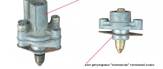
- At the bottom of the carburetor, find the “quantity” adjustment screw, which is responsible for the idle speed. Start the engine. Using the “quantity” screw, set the idle speed to 850-900 rpm according to the tachometer;
- Tighten the “quality” screw (according to emergencies) to gradually lean the mixture. As soon as the engine slows down or starts to misfire, turn it in the opposite direction (to increase fuel) about half a turn until the engine begins to operate normally.
Video of idle speed adjustment (xx).
Float adjustment
The float is adjusted to set the normal level of gasoline filling in the float chamber if the carburetor is overfilled or there are other problems with the fuel supply. To do this, you need to remove the carburetor cover on which the float and needle valve are attached.
Diagram of the main metering systems of the VAZ 2107 carburetor: (1 - main air jets with emulsion tubes; 2 - nozzles of the first and second chambers; 3 - fuel filter; 4 - needle valve; 5 - float; 6 - throttle valve of the second chamber; 7 - main fuel jets; 8 - throttle valve of the first chamber)
- You will need templates to adjust the float. They can be cut out of cardboard (make strips 14 and 6.5 mm wide) or use ready-made measurements;
- Place the removed cover on the end so that the float does not press on the needle valve ball, but only lightly touches it;
- The standard gap between the float and the plane of the carburetor cover should be 6.5 mm. In this case, the float itself barely touches the valve ball, as already mentioned. If the distance is greater or less, you need to bend the float tongue;
- The float stroke to the farthest position should be 14 mm. To measure it, you need to move the float and place a second measuring template between it and the lid. If the distance does not meet the standard, you need to bend the tongue of the float bracket.
The video below very simply shows what the fuel level should be in the float chamber and how to adjust the float.
Setting up the starting system and choke
The starting system is the fuel supply mechanism at start. To start the engine “cold” without putting extra stress on the battery and starter, you need to give an enriched mixture.
Starting device of the VAZ 2107 carburetor: (1 - diaphragm; 2 - adjusting screw; 3 - diaphragm rod; 4 - air damper control lever; 4.1 - lower profile of the groove of lever 4 to limit the maximum opening of the air damper; 4.2 - upper profile of the groove, providing mechanical opening the air damper; 4.3 - edge of the lever to ensure the starting clearance of the throttle valve of the first chamber; 5 - air damper; 6 - air damper lever; 7 - air damper return spring; 8 - air damper drive rod; 9 - adjusting screw stopper; 10 - adjusting screw for slightly opening the throttle valve of the first chamber; 11 - throttle valve drive lever; 12 - throttle valve of the first chamber)
To set up, you will need a 5 mm template (this can also be cut out of cardboard. You can often find a recommendation to use a 5 mm drill).
- Remove the carburetor;
- Close the air damper by turning the lever. This is similar to pulling the choke out of the inside of a car;
- Using a prepared measure, check the distance in the first mixing chamber between the wall and the edge of the air damper. It should be exactly 5 mm;
- If the distance does not correspond to the standard, you need to twist the plug above the adjusting screw (on the side of the body) and tighten this screw with a screwdriver to adjust the correct gap.
Below is a short video on how to set up a “cold start” in a carburetor.
Throttle adjustment
This procedure will allow you to correctly set the amount of fuel that enters the manifold. Operating procedure:
- Remove the carburetor;
- Prepare a measure: a small piece of wire 0.7 mm thick;
- Turn the throttle lever until it closes;
- Using a prepared wire, measure the gap between the throttle valve and the wall; it should be exactly 0.7 mm;
- If the gap is greater or less than this indicator, you need to adjust it by bending the drive rod.
Solex carburetor VAZ2107, how to adjust the float system with your own hands
To adjust the float chamber, you must perform the following actions:
- We check the position of the float and pay attention to the shape of the mounting bracket - if it is deformed, it needs to be aligned. This is quite important, since otherwise the float will not sink into the chamber normally.
- We adjust with the needle valve closed. It is necessary to open the float chamber cover and move it to the side. Next, carefully pull the tongue of the bracket. You should ensure that there is a distance of six or seven millimeters between the float and the cover gasket. After immersion, the distance should be approximately one or two millimeters. If it is significantly larger, the needle must be replaced.
- When the needle valve is open, the distance between the float and the needle should be about fifteen millimeters.
It is worth noting that it is not necessary to remove the carburetor from the engine to perform these steps.
How to remove, install, replace a carburetor
For repairs and maintenance, the carburetor must be dismantled. To work, you will need a set of tools (pliers, open-end wrenches, screwdrivers) and a suitable room. Work is carried out on a cold engine. In short, first you need to disconnect everything connected to the carburetor, and only then remove it. The video below clearly shows the procedure for removing a VAZ 2107 carburetor.
Sequencing:
- Loosen the clamp on the corrugated pipe for the warm air intake, remove the pipe;
- Unscrew the air filter housing fasteners and remove it;
- Remove the suction cable: unscrew the bolt and screw that secure its shell, then loosen the cable itself;
- Remove the hose for removing crankcase gases from the fitting;
- Disable the idle economizer control: remove the wires from the microswitches;
- Disconnect the vacuum ignition timing regulator tube (remove it from the fitting);
- Pull the tube off the economizer;
- Remove the return spring;
- Loosen the clamps securing the fuel hoses, remove the hoses;
- Unscrew the 4 carburetor mounting nuts;
- Remove the carburetor from the studs.
Carburetor replacement is needed less frequently than repair. You can find any spare parts for this device on sale. After adjustment, cleaning and repair, the carburetor can be put back.
The carburetor is installed in the reverse order: first it is placed on the studs, then screwed to the body, and then all communications that were removed are connected to it.
Disassembling and cleaning the unit
Considering that the amount of impurities in our gasoline is simply off scale, cleaning the VAZ 2107 carburetor turns into a necessary procedure. It can be carried out without dismantling and disassembling, or it can be done with complete disassembly of the device.
Cleaning without dismantling, video.
Many car owners periodically treat the carburetor with special cleaning agents (carbocleaners). These aerosols do a good job of removing deposits in gaps, unless, of course, they are perennial “growths.”
- The engine must be turned off and cool before starting work;
- Remove the air filter housing;
- Using a wrench, unscrew the idle speed solenoid valve on the carburetor;
- Use a carb cleaner to treat the carburetor: external surfaces, jet channels (through a thin tube), chambers, air dampers, etc., as far as you can get;
- Leave for 10 minutes for the aerosol to dissolve deposits;
- Run the engine for a couple of minutes. A stream of gasoline will wash away the residue;
- If necessary, repeat the procedure, first waiting until the engine cools down.
If such cleaning does not produce results after twice use, the carburetor will have to be removed and cleaned “like an adult”, with disassembly.
Cleaning with removal, video.
How to remove the carburetor is already clear. Now the sequence of its disassembly:
- Remove the top cover by unscrewing the five mounting screws;
- Unscrew the jets and remove the emulsion tubes;
- Remove the accelerator pump nozzle - unscrew it, pry it off with a screwdriver and remove it;
- Remove the seal located under the valve;
- Remove the diffusers from the chambers using pliers or carefully knock them out with the handle of a screwdriver;
- Unscrew and remove the accelerator pump screw;
- Unscrew the adapter system nozzle holder and remove the nozzle itself;
- Unscrew and remove the idle fuel jet;
- Remove the accelerator pump cover: unscrew the 4 screws in the corners, remove the cover and the pump itself (diaphragm, pusher, spring);
- Remove the return spring from the pneumatic drive lever, then the rod clamp, after which remove the spring from the throttle valve drive lever;
- Remove the pneumatic drive by unscrewing the fasteners;
- Unscrew the 2 screws that secure the lower part of the carburetor to the body, remove the lower part; Remove the economizer and economizer microswitch with bracket;
- Unscrew the screws for adjusting the quantity and quality of the mixture.
This completes the disassembly of the carburetor. After this, you can start cleaning. The parts and body of the carburetor, including the jets, can be washed with kerosene, the seats of the jets and the jets themselves can be blown out with a compressor. It is advisable not to clean the jets with wire; it can damage the holes and then the jet will have to be replaced.
When the layers are washed off the metal, you can inspect it for corrosion, wear and defects. All parts that show signs of wear must be replaced with new ones. The carburetor is assembled in the reverse order, then adjustments are made and you can put it in place.
Lada Semerka
The appearance of the VAZ-2107 was complemented by some elements that were previously used on S-Class Mercedes. And this landmark was taken for a reason. Secretary General Leonid Brezhnev admired German cars and wanted the Union to have its own Mercedes. It was thanks to this brand that the characteristic protruding radiator grille appeared on the “Seven”. In combination with the new hood and design solutions applied to the front of the car, it looked harmonious. Rectangular optics also came in handy. The designers decided that it looks more solid and status than traditional round headlights. In addition, new bumpers (with hydraulic supports), power bars in the doors and tail lights appeared, in which the layout of the light blocks was changed.
A lot of work was done not only on the exterior of the “Seven”, but also on its interior. A modern instrument panel has appeared, a full-fledged instrument cluster (with a voltmeter, oil pressure gauge, tachometer), a new steering wheel, an upgraded heating and ventilation system, anatomical seats with integrated headrests, and much more.
The result was a truly beautiful car, completely in keeping with the spirit of the times. And most importantly, it fit the luxury class and was the most premium of all Zhigulis.
VAZ-2107 appeared in 1982. But work on the model was carried out for quite a long time. Back in 1978, the development appeared to the Chairman of the Council of Ministers of the USSR, Alexei Kosygin. And he already decided the fate of the model. He liked her. And only after this was a decree signed that the “seven” should go into production.
Tuning carburetor VAZ 2107, video
There is always room for tuning in a VAZ carburetor. To a certain extent, it really helps to improve the dynamic characteristics of the engine without interfering with the power unit. As a rule, tuning is done for the purpose of:
- reducing fuel consumption;
- improving engine power output;
- improved acceleration characteristics;
- delays in major repairs or engine tuning.
Carburetor modification and tuning, video.
- Replace diffuser No. 1 with a larger one, install fuel and air jets with non-standard ones, with greater capacity, replace the accelerator pump nozzle, remove the springs connecting the throttle valves to the vacuum pump and replace them with wires. All this is done to supply more fuel-air mixture;
- Replace the repair kit - a set of gaskets and consumables that quickly fail. Often, replacing the repair kit allows you to solve the problem with interruptions in the carburetor;
- Install a sports carburetor instead of the standard one. The sports version has better performance, which significantly improves engine dynamics. Of course, the old “Seven” will not turn into a Ferrari, but it will become a little faster. True, fuel consumption will increase, but this is not important for those who like to drive fast;
- Another step is to install a carburetor from another VAZ model with a more powerful engine. The principle is the same as with the tuning “sports” version - more performance, better dynamics;
- For those who understand, install another carburetor. Oddly enough, a pair of standard carburetors gives an increase in power (which is expected) and at the same time saves gasoline. Such tuning can be done by professional craftsmen who have the necessary equipment, but this is a really interesting option for improving the car.
Main types of DAAZ Carburetors
DAAZ 2107-1107010 - installed on the VAZ 2105, as well as the VAZ 2107.
DAAZ 2107-1107010-20 - installed, as a rule, on new VAZ 2106 VAZ 2103.
DAAZ 2107-1107010-10 – installed on VAZ 2106 or VAZ 2103 engines without a vacuum corrector with an ignition distributor.
At all times, VAZ cars were equipped with a variety of types of carburetors - Ozone, Weber, Solex and others. However, some of them are still popular today. Generally speaking, the types of carburetors are float, bubbler and needle.
In our article we will pay special attention to the “native” carburetor of the VAZ-2107 – “Ozone”. At the same time, I would immediately like to note that these devices come in different series. For example, DAAZ 2107-1107010 was most often installed on “fives” and “sevens”. In turn, the marking of carburetors on “sixes” and “threes” was slightly different - DAAZ 2107-1107010-20 (or a similar type, but with 10 at the end).