The occurrence of any problems with gear shifting does not always mean a serious breakdown of the gearbox. If gears are difficult to engage, difficulties have arisen with selecting a gear, which prevents engagement, etc., then in some cases it is sufficient to adjust the gear shift drive. At the same time, you can adjust the manual transmission drive either at a service station or independently.
Adjusting the gearbox control
1. Shift the gearbox to neutral and press the gearshift adjustment lock until it clicks, thereby locking the mechanism shaft.
2. In the engine compartment, loosen the terminal connection of the gear shift drive, ensuring free mutual movement of the tip of the gear shift lever and the rod.
3. Remove the frame of the gear shift lever cover from the socket of the floor tunnel lining, overcoming the elastic resistance of its clamps, and lift the cover along the lever.
4. Set the gear shift lever to the position of selecting 1st or 2nd gear and, aligning the holes in the thrust bushing of the gear shift lever and the lever slide, fix the lever by inserting a rod with a diameter of 5.0 mm into the aligned holes.
5. Tighten the shift actuator terminal connection, remove the rod from the mounting hole on the shift lever, and return the shift mechanism lock to its original position.
6. Check that the gears are engaged smoothly. Repeat the adjustment if necessary.
Working in the engine compartment, loosen the bolt securing the shift lever rod to the bushing.
Remove the plug from the adjuster hole in the gear shift lever cover.
Looking at the engine compartment bulkhead, grasp the shift lever and turn it clockwise until a 4.5mm twist drill bit can be inserted into the adjuster hole in the shift lever cover.
When working inside the vehicle, pull the front edge of the shift lever boot toward you to gain access to the base of the shift lever.
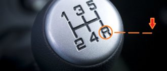
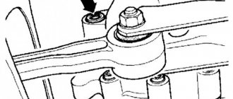
Now you need an assistant to hold the gear change lever in the neutral position of 1st/2nd gear. The lever should rest on the reverse stop, and the arrow and the cutout should be aligned (Fig. 7.5).
Without moving the shift lever, tighten the bolt, securing the shift lever rod to the bushing in the engine compartment.
Check that the free play of the shift lever between the hook (A) and the stop (B) at the base of the lever is within specification (maximum 3 mm) (Fig. 7.6).
Rice. 7.5. The arrow on the gear change lever is aligned with the cutout on the reverse limiter.
Rice. 7.6. The free play of the gear lever between the hook (A) and the limiter (B) should not be more than 3.0 mm
Install the gear shift bellows on the center console.
Remove the twist drill from the adjuster hole in the selector cover and plug the hole with a new plug.
At the end of the work, check whether all gears can easily engage (with the vehicle stationary), but with the engine running and the clutch pedal depressed.
Manual transmission F13 and F17+
1. Adjusting the shift drive is not one of the routine procedures for routine vehicle maintenance and the need for it arises only after removing the shift mechanism. If the clarity of gear shifting is impaired, the proper functioning of the drive can be checked, and if necessary, appropriate adjustments can be made.
2. Adjustment is carried out using the bolt of the clamp securing the gear selection rod to the shift rod (see Section 10). The bolt is located under the power unit, just in front of the rear bulkhead of the engine compartment. On most models, access to the screw is possible from above, for which you must first remove the battery with the tray (see Chapter 5).
3. Loosen (but do not loosen completely) the bolt of the gear selector rod clamp.
4. Inside the car, release the gearshift lever boot from the clamps and screw it up. Fix the lever using a special device KM-527-A (see accompanying illustration) or another suitable tool, threaded into the clamp on the left at the base of the lever and tucked into a special fixing hole.
5. With the shift mechanism in the neutral position, rotate the selector shaft against the resistance of the spring and lock the mechanism in this position by sinking the spring-loaded locking pin into the cover located on top of the transmission housing (See accompanying illustration).
Why do you need a gearbox slide?
In fact, most often the gearbox is in good condition, but the rocker may fail.
You can replace the unit with a new one, or you can get by with proper adjustment of the rocker. Adjusting this element will help troubleshoot problems and make sure that the problem is related specifically to the gearbox linkage. It happens that a car owner simply begins to change one component after another without understanding the problem, wasting money and time to no avail.
What's the result?
As you can see, problems with gear shifting do not always mean that expensive or major gearbox repairs are necessary. In many cases (if there are no other signs and reasons), it is enough to know how to adjust the gearbox, that is, the linkage on a manual transmission. However, you can perform this procedure yourself.
In this case, correctly adjusted automatic transmission cables allow you to get rid of jerks and kicks of the automatic transmission, as well as achieve smoothness and precision during gear shifting.
Why may it be difficult to engage gears or why first gear, second, reverse, etc. may not engage? The main causes of gearbox malfunctions, recommendations.
Gears are difficult to engage or speeds on a manual transmission do not engage: the main causes of the malfunction and possible problems.
What is a gearbox rocker: the design of the gearbox rocker, signs of malfunctions. Adjusting the gear shift link. Recommendations.
Why is it necessary to check and adjust the automatic transmission cable when jerking occurs during automatic transmission gear shifting? Adjusting the automatic transmission cable.
Removing the gearbox: dismantling the manual transmission and automatic transmission. The procedure for removing the gearbox, what needs to be taken into account, recommendations.
How to replace an automatic transmission with a manual transmission, as well as replacing a manual transmission with an automatic transmission: nuances. Useful tips and tricks.
Box device
In order to understand the essence of further manipulations, you will need to familiarize yourself with the structure and functions of the gearbox equipped in the domestic brand of car VAZ 2110.
Gearbox: 1 — rear cover of the gearbox housing; 2, 44 - nuts; 3 — fifth gear drive gear; 4 - thrust plate; 5, 40 — retaining rings of bearings; 6 — ball bearing of the input shaft; 7 - fourth gear drive gear; 8 — gearbox housing; 9 — input shaft; 10 - third gear drive gear; 11 — drive gear of the second gear; 12 — reverse gear; 13 — drive gear of the first gear; 14 - roller bearing; 15 — breather; 16 — input shaft oil seals; 17 — clutch housing; 18 — roller bearing of the secondary shaft; 19 — oil sump; 20 — drive gear of the main gear; 21 — plastic drive gear of the speed sensor drive; 22, 32 — drive oil seal; 23, 30 — tapered roller bearing of the differential; 24 — speed sensor drive; 25 — differential box; 26 — differential satellite; 27 — satellite axis; 28 — semi-axial gear; 29 — driven gear of the main gear; 31 — adjusting ring; 33 — driven gear of the first gear; 34 — synchronizer of first and second gears; 35 — driven gear of the second gear; 36 — third gear driven gear; 37 — synchronizer for third and fourth gears; 38 — fourth gear driven gear; 39 — ball bearing of the secondary shaft; 41 - bushing; 42 — fifth gear driven gear; 43 - fifth gear synchronizer.
Operating principle of the gearbox:
- Stable gear shifting is ensured by the input shaft, consisting of a block of gears. These parts are always engaged with the drive gears of 1-5 gears.
- The main drive control gear is built into the second shaft. The synchronizers placed on it are responsible for the forward movement of the driven gears. The bearing and oil sump are located nearby.
- The controlled gear wheel of the final drive is attached to the two-satellite differential of the tens by means of a box flange.
- The drive is equipped with mechanisms for selecting gears and shifting them, rods, a selection rod, ball joints and a shift knob.
- Overshoot of speed is prevented by jet thrust, the ends of which are attached to the engine and support.
Gear shift mechanism drive - removal, installation and adjustment
To perform the adjustment you need:
— inspection hole or overpass;
1. We prepare the car for work (see “Preparing the car for maintenance and repair”).
2. Remove the floor tunnel cover (see “Floor tunnel cover - removal and installation”).
10 mm spanner
Unscrew the screw and two nuts securing the plastic lining that blocks the engagement of reverse gear.
4. Remove the cover from the bracket.
10 mm socket wrench
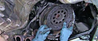
Unscrew the six nuts securing the pressure plate.
6. Remove the pressure plate from the studs.
7. Remove the rubber cover.
8. Remove the jet rod (see “Jet rod - removal and installation”).
9. Mark the relative position of the drive rod and the hinge.
13 mm spanner
Unscrew the nut of the coupling bolt and unclench the clamp.
11. Disconnect the rod from the gear selection mechanism hinge.
12. Remove the rod assembly with the lever and clip from the car.
We install the rod in the reverse order and apply grease to the threaded part of the rod mounting bolts, aligning the marks made before disassembly.
To adjust the drive, a special template is required, but if it is not there, the drive can be adjusted with the help of an assistant
1. Using a slotted screwdriver, remove the decorative cover of the gear shift lever from the floor tunnel lining and lift the cover up.
2. Disconnect the gear shift rod from the hinge (see above, paragraphs 8-10).
3. By slightly turning the gear selection mechanism hinge counterclockwise, we engage first gear (do not confuse it with reverse gear).
4. We connect the rod with the hinge and make sure that:
a) an assistant holds the gear shift lever in the first gear engaged position; in this case, the reverse gear engagement limiter touches the plastic lining of the bracket;
b) the distance from the axis of the rear pin of the lining to the limiter is approximately four centimeters.
5. Tighten the nut of the rod clamp.
6. Make sure that all gears can be engaged, including reverse gear, and if necessary, repeat the adjustment.
Adjustment of the remote drive for controlling the gear shift mechanism in transmissions of models 142, 152 is carried out with the gear shift lever in the neutral position in the following order:
- loosen the coupling bolts 5 (see Fig. Adjusting the drive) and, having unscrewed the bolts 3, ensure clearance in the connection by screwing the adjusting flange 4 onto rod 6 one or two turns;
- Having loosened the lock nut 1, screw in the set screw 2, thereby stopping the movement of the rod 7;
- having loosened locknut 1 (see Fig. Set screw and lock nut), screw in set screw 2, thereby stopping the movement of the gear shift lever;
- rotating, move the adjusting flange 4 along the thread (see Fig. Adjusting the drive) until it makes contact over the entire surface with the flange of the rod 7. Install bolts 3 and tighten the coupling bolts 5;
- Unscrew the set screw 2 by 21 mm and lock it with a lock nut;
- Unscrew the set screw 2 (see Fig. Set screw and lock nut) by 31 mm and lock it with the lock nut.
Set screw and lock nut: 1 - lock nut; 2 - set screw
Drive adjustment: 1 - lock nut; 2 - set screw; 3-bolt; 4 — adjusting flange; 5 — coupling bolt; 6 - traction; 7 - rod
Gear ratios
L—lowest gear in the divider; S—highest gear in the divider; R - reverse; C - low gear
Check the installation size of the gear divider valve stop (if equipped) for the 152 gearbox by moving stop 4 of the valve stem. After setting the required value A = 20.5 ± 0.5 (see Fig. Clutch drive), secure the stop with nuts, lock the nuts with bend washers.
Clutch drive: 1 — dust fuse; 2 - cover; 3 — rod limiter; 4 — stop (flag) of the valve stem.
Check the stroke of the gear divider lever with compressed air in the brake pneumatic drive. To measure:
- remove cover 1 (see Fig. Divider mechanism) of the inspection hatch of the gear divider shift mechanism;
- press the clutch pedal all the way;
- By moving the gear divider control switch (see Fig. Gear shift diagram) from the upper position to the lower position or vice versa, measure the stroke of the lever in the center of the hole. The normal stroke value is -16.5. 19.0 mm.
Divider mechanism: 1 — inspection hatch cover; 2, 5 - setscrew; 3.4-lock nut.
The lever stroke must be adjusted in the following order:
- loosen locknuts 3, 4 (see Fig. Divider mechanism) and unscrew the set screws 2, 5;
- set the switch on the gear lever handle to the lower position (H);
- press the clutch pedal all the way;
- screw in the rear set screw 5 until it makes contact with the lever, then tighten it another ¼ turn and lock it with locknut 4;
- Set the switch to the upper position (B) and press the clutch pedal all the way. Screw in the front set screw 2 in the same way as the rear screw was screwed in.
Adjust the control drive of the model 152 gearbox with the possibility of using the power take-off box on the upper hatch and on the flywheel housing with the gearshift lever in the neutral position in the following order (see Fig. Control drive of the gearshift mechanism of the model 152 gearbox):
- unscrew bolts: 3, 7;
- fix the rod F in the neutral position by loosening the nut 8 and screwing in the screw I;
- fix rod 4 with technological rod P (d=3mm, 1=100mm) in part 1;
- screwing part 6 until it comes into contact along the entire plane with the flange of the rod F, connect the rod 2 with the rod F with bolts 3;
- fasten part 6 to the rod with 2 bolts 7, tightening them to a torque of 50...70 Nm;
- remove the technological rod;
- install rod 4 vertically, changing the length of rod 5, turning rod 5;
- Unscrew screw I to the specified length and lock it with nut 8.
Drive for controlling the gear shift mechanism of the model 152 gearbox 1-gear shift lever support; 2 — rear thrust; 3.7-bolts; 4-thrust; 5 — transverse thrust; 6-flange coupling adjustment; 8 - nut; I - screw; P—technological core; F - rod
Adjust the remote drive for controlling the gear shift mechanism of transmissions of models 144, 154 and ZF 9S109 (see Fig. Drive for controlling the gear shift mechanism for models 144, 154 and Drive for controlling the gear shift mechanism for models ZF-9S109) with the gear shift lever in neutral position in the following order:
- loosen nut 11;
- completely unscrew nut 10;
- remove shank 9 from the conical hole of lever 5, releasing rod 3;
- fix rod 3 with technological rod 4 (d = 4 mm, 1 = 100 mm) in support 2;
- set lever 5 at angle B: — 20° ±2.5° (for gearbox mod. 144), — 17° ±2.5° (for gearbox mod. 154), — 19° ± 2° (for ZF -9S109) to the vertical;
- Rotating shank 9, align the axis of the conical pin with the hole in lever 5, tighten nut 10 to a torque of 40.50 Nm;
- holding shank 9 from turning with a wrench, tighten nut 11 to a torque of 98.147 Nm;
- remove the technological rod;
- loosen nuts 8;
- By changing the length of rod 7, ensure the position of lever 1 and rod 3 in the vertical plane. Deviation of lever 1 and rod 3 from the vertical is no more than 2 mm;
- tighten nuts 8 to 40...50 Nm.
Drive for controlling the gear shift mechanism of models 144, 154. 1 - gear shift lever; 2 — gear shift lever support; 3 - traction; 4 - rod; 5 — lever; 6 — thrust bracket; 7-jet jet; 8, 10, 11-nut; 9-shank
Gear shift mechanism control drive model ZF-9S109 1 — gear shift lever; 2 — gear shift lever support; 3 - traction; 4 - rod; 5 — lever; 6 — thrust bracket; 7 — jet thrust; 8, 10, 11 - nut; 9 - shank
For a model 154 gearbox, if necessary, adjust the position of bolt 1 on the clutch pedal (see Fig. Adjusting the bolt on the clutch pedal of a model 154 gearbox):
- screw in bolt 1, having first unscrewed its locknut;
- press the clutch pedal all the way down;
- Unscrew bolt 1 until its spherical part comes into contact with the plane of the head of the valve stem for switching on the divider 4;
- additionally unscrew bolt 1 approximately 4 - 4.5 turns; ensuring that the head is recessed by 5 - 6 mm when the clutch pedal is pressed all the way;
- tighten the locknut of bolt 1.
Adjusting the bolt on the clutch pedal of the model 154 gearbox 1 - adjusting bolt; 2 — clutch pedal; 3 — front panel; 4 — valve for switching on the divider; 1 - to the center differential lock valve
Adjustment of the remote (side) drive for controlling the gear shift mechanism in the gearbox of the model ZF-9S1310 (see Fig. Drive for controlling the gear shift mechanism of the gearbox of the model ZF-9S1310 with a KAMAZ engine) is carried out with the gear shift lever H1 in the neutral position, maintaining a dimension of 0251 mm , in the following order:
- loosen nut 8;
- completely unscrew nut 9;
- remove shank 6 from the conical hole of lever 5, releasing rod 3;
- fix rod 3 with technological rod 4 in support 2;
- set lever 5 at an angle of 19±3° to the vertical;
- Rotating shank 6, align the axis of the conical pin with the hole in lever 5;
- tighten nut 9 to 50.70 Nm;
- end K of shank 6 must be parallel to the plane of lever 5. In this position, holding shank 6 from turning with a key, tighten nut 8 to a torque of 98.147 Nm;
- remove the technological rod;
- loosen nuts 10;
- By changing the length of rod 7, ensure the position of lever 1 and rod 3 in the vertical plane. Deviation of lever 1 and rod 3 from the vertical is no more than 2 mm;
- tighten nuts 10 to a torque of 40.55 Nm, while the ends M of the ball ends must be parallel to the brackets 11 and 12 to which they are attached.
Drive for controlling the gear shift mechanism of the ZF-9S1310 transmission with KAMAZ 1 engine - gear shift lever; 2 — gear shift lever support; 3-thrust; 4-rod; 5-lever; 6- shank; 7 — jet thrust; 8, 10 — lock nut; 9 - nut; 11, 12 — bracket; C = 251 mm - size for neutral position H1
Checkpoint diagram
The gearbox design is as follows:
- To ensure gear shifting, the gearbox contains a primary shaft consisting of a gear block. They are constantly engaged with the drive gears from the first to the fifth speed (that is, those that are oriented towards driving forward);
- The secondary shaft is equipped with a drive gear for the main transmission, and it also has gear synchronizers that ensure forward movement of the driven gears. There are also bearings plus an oil sump;
- VAZ two-satellite differential, with the driven gear of the main gear attached to the flange of its box;
- the gearbox drive consists of a gear shift knob, a ball joint, a selector rod, a rod, gear selection mechanisms, and gear shifting mechanisms;
- Jet thrust is designed to protect the gearbox from flying out of gear. Its ends are attached to the support and the power unit.
Gear shift drive diagram
How to adjust the rear derailleur while riding
If while driving you feel that the chain is not being thrown onto the larger sprocket (to reduce speed), tighten the cable a little. This can be done by UNLOCKING the nut. Don’t turn it too much - one click - a quarter turn - drive around, click the shifters. We switched the speeds, checked, if not enough - one more click.
If you overtighten, the chain may begin to shift poorly onto the smaller sprocket (to increase speed). And to give it the opportunity to fold correctly, tighten the nut one click. Then check - if it’s not enough, then check for one more. Also drive around and change gears. Well, if you loosened it too much, then turn it back one click at a time
Shimano Deore, Shimano XT level shifters will need to be slightly adjusted every 500-700 kilometers. If the switch class is lower, then more often. Also, if you have cheap shirts and cables, they will “stretch”. As a result, the setting will float away.
Fighting the ringing
Typically, a ringing sound appears after adjusting the gear shift lever. To correct this drawback, you need to install a spring to hold the lever. The development of mechanical engineering makes it possible to replace the parts of the VAZ 2110 backstage with similar, but more advanced ones. For a VAZ car, the Kalina rocker is ideal.
In this case, the cardan from the new model is modified to be 20 mm longer than on the ten. This sound is directly related to the part itself; the Kalina rocker has no play, and all the vibration is transmitted into the car interior, to the gear shift lever itself. The easiest way to get rid of rattling is to install a spring.
Manual transmission F23 and M32
8. On these boxes, the gear shift drive is made using cables (see accompanying illustration).
9. Remove the center console cover and shift lever boot (see Chapter 11).
10. Carefully prying with a small screwdriver, release both latches of the drive cables (see accompanying illustration).
Attention: Be careful when pressing the latches; excessive force may cause them to break!
11. On the F23 manual transmission, in the engine compartment, set the transmission to the “neutral” position, then move the gear shift lever in the car interior to the neutral position and lock it using the lock (see accompanying illustration)
12. On manual transmission F32, pull the reverse gear lock latch up and squeeze the 2 locking tabs (see illustration 9.12a) so that the spring-loaded locking block of the gear shift lever goes down. Using the locking block, lock the lever in the neutral position (see illustration 9.12b) Then remove the battery with the tray (see Chapter 5) and fix the actuator rod using the KM-527-A tool or other suitable tool (see illustration 9.12 c) gear shift drive.
13. Pressing back, lock the clamps of both cables (see accompanying illustration).
14. Reinstall all removed components, then check that the switching mechanism is functioning properly.
Preparing to adjust the rocker
On an old car, it is better to lubricate the linkage mounting assembly with a penetrating compound in advance.
Before starting adjustment work, you need to prepare the place and carry out the following preparatory measures:
- The car needs to be parked in a pit.
- The handbrake must be tightened all the way.
- It is mandatory to install wheel chocks.
For a faster and better adjustment process, it is better to perform all work with an assistant. The process itself can occur in several ways.
First adjustment method
To adjust, you need to loosen the clamp connecting the rocker drive to the cardan.
This method is the simplest. In this case, the gearbox linkage is adjusted according to the reverse speed . First of all, you need to loosen the clamp, after which the reverse gear is engaged. Then you need to position the lever in the position you need. After this, the clamp is tightened and the operation of the entire mechanism is checked.
If you don't succeed the first time, you need to listen for knocks and crackles when switching . They must either decrease or increase. In accordance with this, you need to position the lever in the desired direction. If all manipulations do not lead to the desired effect, you need to resort to another adjustment method.
Second adjustment method
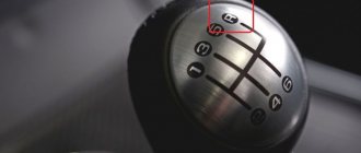
The gear shift lever should rest against the locking plate (in the photo it is made of light plastic).
This method is used if the first one did not lead to the desired results. When using it, you can more clearly position the gearshift lever. This method is as follows:
- The gearshift lever switches to first speed.
- The backstage clamp is completely loosened.
- Next, you need to turn the drive of the rocker itself counterclockwise until the lever rests against the reverse speed stop.
- The backstage clamp is tightened.
Tighten the clamp fastening nut, eliminating the shift of the rod during operation.
It happens that some VAZ-2110 cars do not have a plastic limiter retainer, so the adjustment in this case is carried out not in first gear, but in neutral.
Third adjustment method
This method is quite complicated , as it involves calculating the depth of the gearbox linkage to the cardan. Due to this, the position of the lever in the neutral position can be accurately calculated and adjusted. It happens that if the calculation is not accurate enough, all manipulations only lead to the appearance of rattling when changing gears.
If adjustment by any of the above methods does not lead to the desired results, several options are possible to solve the problem:
- Carry out diagnostics at a service station to make sure that the problem is in the gearbox linkage.
- You can replace the gearbox linkage.
- You can contact specialists who will adjust the slide themselves.
| After performing work related to disconnecting the gear shift drive, and if gear shifts are unclear during operation, adjust the gearbox drive. You will need: keys “12”, “14”. |
Video on how to permanently get rid of a rattling gear lever
If you notice that in your car the free play of the gear shift link has increased, the clarity of shifting has disappeared, or it is even difficult to catch a gear, you have problems with a broken gear shift drive.
There are two ways to solve this problem.
1. The first method is simple, but expensive. It provides for a complete replacement of the drive.
2. The second method is cheap, but quite troublesome. This method involves purchasing a gear shift drive repair kit.
So, if you decide to do everything yourself, then I suggest you first get everything you need.
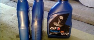
Today, at any car market you can find a repair kit, which consists of:
1. Gear selection rods;
2. Five plastic bushings with rubber rings.
However, that's not all; with this kit you will need to purchase another large shift drive axle and two small ones with springs and locks. Along with repairing the gear shift drive, I would advise replacing the rod and oil seal on the gear shift mechanism. This must be done, because usually the rod eyes have a large hole.