Replacing the emergency stop button on a VAZ
Any owner of a VAZ car has probably encountered problems with the emergency stop button.
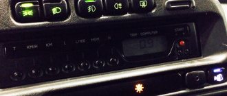
The most important of them is the awkward position of the standard emergency tape on the steering gear cover, which is difficult to reach without distracting the eye. This is especially inconvenient and even dangerous when driving.
Often there are problems with the built-in latch, when when the alarm is on it is therefore difficult to turn it off because the button gets stuck. Then you need to completely remove the safety tape and adjust the latch.
All these difficulties can be easily solved with the help of the new euro button, which can be purchased at any online store. After reading this article, replacing the emergency bracelet button will not be difficult even for a beginner.
Signs of malfunction of the mass air flow sensor
Summary of the article:
Precise operation of the engine is impossible without proper operation of all its elements and assemblies separately. One of them is the mass air flow sensor. It measures the air entering the engine cylinders and transmits the data directly to the ECU. This ensures an optimal oxygen/fuel ratio, resulting in maximum engine efficiency.
Why you may need to replace the ignition switch
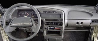
VAZ 2114 instrument panel pinout
There can be several reasons for this problem, the most common are:
- After all, a broken lock is constantly subject to wear and tear.
- Lost keys.
- Damage due to attempted theft.
- Faulty connector with wires.
The malfunction is easy to determine when the engine is running, if you do not hear the sound of the starter, the relay is triggered, or the electrical equipment simply does not turn on. There are several ways to determine the source of the problem:
- diagnostic;
- visual.
First, you need to check the machine’s reaction to different positions of the key in the lock. First you need to put the key in position number one, also known as the ignition. If the module is OK, the entire electrical system of the vehicle should work. However, if the electrician fails completely or partially, we can conclude that the lock is damaged.
In position number two on the key, the engine starts and the starter engages. If when you turn the key you do not hear the sounds of the starter (turning), as well as the sound of the relay clicking, the ignition switch or the starter itself is broken. In this case, you need to run diagnostics to get more detailed information about the problem.
In this case, you will need a multimeter set to ohmmeter mode. Also, before removing or installing the unit, you must remove the steering column cover.
- + 12V for the microswitch of the inserted key sensor;
- the mass arrives with the driver's door open;
- leaves + 12V to the starter (pin 50);
- + 12V starts after inserting a pin (pin 15);
- + 12V goes out when the key is inserted into pin 5 of the BSK;
- + 12V for lighting the lock cylinder;
- + 12V comes from the battery (pin 30);
- not used.
- The first thing to do is disconnect the ignition switch power connector.
- Then connect the multimeter to the fourth and seventh wires, then do the same with the fifteenth and thirty wires respectively.
- Turn the key in the lock to position number one. If the assembly is not damaged during testing, the multimeter should show zero resistance value.
- Next, you need to turn the key to position number two. The resistance on the multimeter screen, as in the case described above, should be zero.
In a situation where, after checking the lock with a multimeter, the resistance value in at least one of the cases was not zero, it is necessary to replace it. Otherwise, the lock is in good condition and other parts of the vehicle should be checked for damage. To work, you need to prepare spare parts and other accessories.
You will need a new power switch. It is quite easy to find original and analog parts on the Internet, but it is worth considering that it is advisable to purchase a “padlock.”
The number of the original VAZ 2114 ignition switch in the catalog is 21103704010. Estimated price: for a used part 500 rubles, for a new one 1200 rubles.
As a replacement, you can use analogues with numbers: 09401, 24370407. Estimated price: 1000 rubles (new part). In addition to the lock itself, you will need the following tools:
- English keys;
- chisel;
- pliers;
- screwdriver.
Before starting work, you must also remove the steering column cover and steering column switches.
How to check the lighting devices in the Chetyrka?
The verification procedure is carried out as follows:
- First you need to make sure that you are using a working fuse. The fuse box is located in the engine compartment, in the compartment between the engine and the windshield, opposite the driver's seat. Bend the latches and remove the cover, then carefully inspect the inside. It contains a diagram that will help you figure out which fuse is responsible for the operation of a particular equipment. Remove the fuse responsible for the functionality of the software and carefully inspect it - if the fuse inside is melted or damaged, the fuse must be replaced. But even if there is no visible damage, you need to insert another one with the appropriate rating into the socket of the removed fuse.
- If this does not help restore the software, then check the relay, it is located in the same block. Typically, the turn signal relay has a hazard warning symbol on it, you need to pull it out and replace it with a working one. To do this, it is not necessary to buy a new relay; you need to pull out another working device and install it. If the emergency lights and software do not work, then we continue checking.
- Now we need to diagnose the light bulbs, but such a check will be required if only part of the turns does not work. Open the hood or trunk and remove the headlight protection, then remove the light sources from their seats. Install a known working device in place of the removed lamp and check how it works. If there are no changes, we move on.
- It is necessary to check the integrity of electrical circuits. To do this, you will need a test lamp with two wires connected to it. One end should be connected to the negative of the battery or the body of the Four, and the second wire is connected to the contact of the electrical circuit being diagnosed. If, as a result of the connection, the lamp begins to light, this indicates that the section of the wire being tested is in good condition. The remaining circuits are checked in the same way. If you find a place where there is no current, then this indicates that there is a fault between the place being tested and the last point where the voltage was. Damaged wires must be replaced.
- You also need to check the quality of contacts on all electrical circuits. Check the contacts in the mounting block, on the base in the vehicle's optics, on the light alarm button and on the steering column switch. Often the cause of problems is oxidation; such contacts must be cleaned or replaced.
How to remove and connect the euro hazard warning button on a VAZ
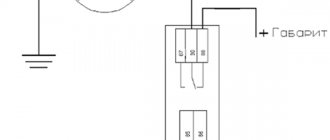
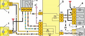
Before you begin installing the emergency bandage, you should familiarize yourself with the connection diagram for the Euro button on the VAZ-2114 (2115), which we will use as an example.
This circuit avoids the use of relays and interference with standard wiring.
- I connected the contacts of the old connector “1” and “3” to terminal “2” of the emergency button;
- Output “2” to the button - to output “D”;
- Contact “7” - for contact “1” on the button”;
- Conclusion “B” - to the backlight;
- Conclusions “A” and “C” are massive;
- Terminals “8” and “4” in the old terminal block are connected by a jumper.
To replace the emergency button we need the following:
- Euro button with padlock underneath;
- Two 1N4007 diodes;
- Welder;
- LTI-120 flow;
- Screwdriver;
- Two terminals.
Having prepared all the necessary tools, we proceed to replacing the old emergency bandage using the example of a VAZ-2114 (2115) car and alarm switch 2515 996.3710-07.10 according to the diagram above.
First you need to disassemble the emergency button in the following sequence:
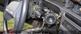
- Using a screwdriver, remove the steering cover;
- We remove the chip from the old switch and the switch itself from the housing;
- Unscrew the two screws and remove the side panel on the driver's side;
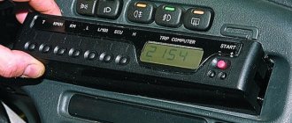
- We take out the released microcircuit into the window where the on-board computer is usually located;
- We disassemble the old emergency button using a flat screwdriver - there are two recesses; by prying it off, it can be divided into two parts;
- We keep the lock of the old emergency tape connector for ourselves; the spring can be pushed out - we won’t need it anymore.
- Then we proceed to connecting new contacts and the switch:
- To obtain a reliable seam, the contact surfaces must first be tinned with LTI-120 acid;
- Contacts “4” and “8” of the microcircuits are immediately connected to each other using wiring;
- On the same microcircuit, on contacts “1” and “3” we solder two diodes with cathodes and connect the anodes to each other;
- The wires of the new switch from contacts “2” and “D” are soldered to the free anodes of the diodes;
- In order for the triangular hazard warning sign to flash, the wire of contact “2”, designated in the diagram as “to order”, is brought to the instrument panel and connected to a free contact (do not forget to insert the lamp bulb along the ordinate axis, since it is not supplied by the factory );
- Solder the wire from contact “1” of the emergency button to contact “7” on the microcircuit;
- The remaining contacts of the connected switch “A” and “B” go to ground and backlight, respectively. Take two wiring terminals and solder them to pins "A" and "B". If necessary, this will allow you to remove all new cables without affecting the old wiring;
- We connect the new harness to the wiring and connect the free ends of contacts “A” and “B”, to which the terminals were soldered, to the microcircuit hanging freely on the fog lights.
Connect the ground and backlight, insert the button. All is ready!
Note that jumpers "4" and "8" in the old hazard switch terminal block allow the hazard kit to be used even when the ignition is off.
This is the only side effect of such a connection, but it is insignificant, because no one forces the alarm to go off when the ignition is turned off.
In this case, there is no need to use a relay, and, as mentioned above, the button can be painlessly removed for factory wiring at any time.
Even a person who is far from such connection diagrams can independently replace the alarm button on a VAZ. Financial costs are minimal, the procedure time is a maximum of 30 minutes. The end result is that your vehicle will have a modern hazard light located in a convenient location.
Connection diagram
The ignition module is part of the space under the hood, it’s easier to find it by the position of the high voltages, they go from the spark plugs straight to it.
Ignition coil diagram:
This diagram is good to follow when you have to replace the ignition coil of a VAZ 2114. In principle, everything is transparent: from contacts with the controller (ECU) to high-voltage wires. The name of the circuit is often common under the name ignition coil pinout: the pinout is a visual representation of the functionality of the device's contacts, which are numbered according to their purpose.
It can be connected in two different ways: when the ignition system coil is removed and when it is directly in its place in the car engine.
If you are holding the module in front of you:
- Let us recall the diagram: the first and fourth contacts are on one winding, the second and third – on the other (they are numbered in the diagram!)
- Then, the lower explosive contact (left) goes to the first cylinder
- On the second - upper explosive contact (left)
- The third cylinder goes to the upper explosive contact (right)
- On the fourth – lower explosive contact (right)
If the module is plugged into the engine, then pinouting the explosive contacts will be more difficult, because the device stands at an angle (as if in a diamond):
- We throw the central lower contact onto the first cylinder
- On the second - left contact
- We put the upper contact on the third cylinder
- On the fourth - right contact
Of course, the first installation option is more convenient, especially since the explosive wires require increased care in the nature of the connection (mixed up and won’t start, in the worst case, the entire engine system is ruined). Speaking to the point, it is clear that the connection diagram for the VAZ 2114 ignition module is not complicated.
By the way, buying an ignition coil is not a cheap pleasure; the price of an ignition module for a VAZ 2114 ranges from seven hundred to a thousand rubles, depending on the location of your city on the map of our country (for more information about how much an ignition module for a VAZ 2114 costs, you can find out by calling a disassembly service or a spare parts store, the running part is almost always in stock).
Materials
1. Electrical tape (preferably blue, as it is especially strong) 2. Four-pin relay for direction indicators from VAZ 2106 3. Relay socket 4. Six-pin alarm on/off button 5. Socket for the button 6 Cable for installing and connecting the above. Tools: 1. Pliers with wire cutters 2. Flat-head screwdrivers 3. Phillips screwdrivers 4. 10mm wrench 5. Knife For those who want to save money due to manufacturability: you can also use your own relay from the VAZ 2101, but in this case adequate operation is not guaranteed, so as this relay is very sensitive to load fluctuations. For this reason, the next installation method is to replace the relay with a more modern one. Let's get started, unscrew the nut securing the turn signal relay and disconnect the three multi-colored wires from it. Next, we determine where to install the panic button. Here we give freedom to our imagination, but a lot also depends on what kind of panel is installed in your car. To the second contact of the relay we connect the wire removed from the contact of the old relay, marked with the letter “L”, and connect it all to the seventh contact of the panic button. We connect the first contact of the emergency relay to the fourth contact of the button. We connect the third contact of the relay to the wire extended by contact “P” of the old relay. We connect the wire from the fourth contact of the relay to the body. The best solution would be to secure the wire under the nut of our relay.
Diagram of the emergency (signal) range for the VAZ 2101 car
Now tighten the relay mounting nut with moderate force so as not to break the plastic holder. Then we connect the second contact of the button to the positive wire of the old relay. The first and third contacts of the button are connected to the turn signal switches on the steering column in any order. The eighth contact of the button is connected to a constant “plus” (regardless of the position of the key in the ignition switch). It is recommended to protect this circuit with a fuse. The most suitable would be to install a fuse rated 8A. Next, you should wrap the wires with electrical tape and secure them so that they do not hang down, install all previously removed casings and panels. Now we have a full-fledged alarm system, and we can heal a new full-fledged life. The entire procedure for installing an alarm on a VAZ 2101 takes 2-3 hours.
Relays and fuses VAZ 2114
- F1 for rear fog lights 10 Amp (A) and rear fog light indicator lamp.
- F2 10 A direction indicators, direction relay, hazard warning group, hazard warning light.
- F3 7.5 A Lampshades for interior lights (both) and trunk, ignition lights, transmission control warning light, brake lights, computer, if equipped.
- F4 20 A support, rear window relay and resistor.
- F5 20 A horn and corresponding relay, cooling fan.
- F6 30 A power windows and relative relays
- Electric heater motor F7 30 A, headlight washer, windshield washer, cigarette lighter, glove box light, winding relay for turning on the rear window heating.
- F8 7.5 There is fog on the right.
- F9 7.5 Left fog lamp.
- F10 7.5 Left side, lamp signaling the inclusion of side lights, lamp for illuminating the sign, engine compartment, switch and instrument lighting, instrument lighting switch.
- F11 7.5 A right side.
- F12 7.5 A low beam right.
- F13 7.5 A low beam on the left.
- F14 7.5 Left high beam and a lamp indicating that the high beam is on.
- F15 7.5 A on the far right.
- F16 30 A - warning light indicating insufficient oil pressure, brake fluid level, parking brake, low battery, instrument cluster, lamp control relay, control system indication, reversing lights, direction indicators and related relays, and alarm system, if the turning mode is turned on, the ECU, the generator excitation winding when starting the engine.
General information about turn signals
If you read the history of the car, this part was not originally included in the kit, and drivers installed it additionally for a fee. In modern cars, turn signals are often located on or near the headlight, whichever comes first. The rear turn signal is installed near the headlight. Repeaters of this necessary part can be placed on the wings and on the mirrors. There is a technology for duplicating mirrors using diode lamps. Now this is considered the most progressive.
The direction indicator consists of the following parts:
- mechanical drive (for starting and stopping);
- switch (for connecting lamps to a power source);
- relay to close and open the circuit after a certain time.
Some cars have a very good functional solution - a triple flasher with a quick press, drivers really like this quality.
If not, you can install a device that increases the number of signals.
When the turn signal is turned on, a characteristic sound is heard. In modern cars it can be changed to a more pleasant one. This part of the car gives off a bright yellow glow, sometimes mixed with orange. On American models they are sometimes red, which leads to an increase in traffic accidents because they are confused with stop signs.
Traditionally, they are turned on as a malfunction indicator - “emergency mode”. The turn signal is a kind of language for drivers to communicate on the road. Overtaking and other circumstances may become undesirable.
Turning your turn signals on in a timely manner is an indicator of your ability to drive and control the situation on the road.
Car electrical equipment
1 — lighthouse block; 2 — gear motors for headlight washer*; 3 — fog lights*; 4 - room temperature sensor; 5 — sound signals; 6 — engine compartment lamp switch; 7 — electric motor of the cooling system fan; 8 — VAZ 2114 generator; 9 — low oil level indicator sensor; 10 — washer fluid level sensor; 11 — front brake pad wear sensor; 12 — cable lugs connected to the common windshield washer pump**; 13 — windshield washer pump; 14 — headlight washer pump*; 15 — end of the cable for connecting to the rear washer pump on VAZ 2113 and VAZ 2114 cars; 16 — low oil pressure indicator sensor; 17 — engine compartment lighting lamp; 18 — wire tip for connection to the engine control system harness or to the ignition system harness on carburetor vehicles; 19 — electric motor of the windshield wiper; 20 — VAZ-2114 starter device; 22 — coolant temperature indicator sensor; 23 — reversing light switch; 24 — sensor for insufficient brake fluid level indicator; 25 - battery; 26 — sensor for insufficient refrigerant level indicator; 27 — relay for turning on fog lights; 28 — mounting block; 29 — brake light switch; 30 — socket for a portable lamp; 31 — illumination lamp for the beacon’s hydrocorrecting scale; 32 — parking brake warning lamp switch; 33 — block for connecting the backlight; 34 — switch for instrument lighting lamps; 35 — switch on the steering column; 36 — alarm switch; 37 — front seat heating element relay; 38 — ignition switch VAZ 2114; 39 — rear fog lamp circuit fuse; 40 — front seat heating element fuse; 41 - locking circuit fuse; 42 — front ashtray lighting lamp; 43 — ignition relay VAZ-2114; 44 — cigarette lighter; 45 — glove box lighting lamp; 46 — glove compartment lighting switch; 47 — heater fan electric motor; 48 — additional resistance of the heater electric motor; 49 — heater fan switch; 50 — heater switch backlight; 51 — lamp for illuminating the heater levers; 52 — Gear motors for electric windows of the front doors; 53 — right front door power window switch (located in the right door); 54 — gear motors for front door locks; 55 — cables for connecting to the front right speaker; 56 — gear motors for locking the rear doors; 57 — cables for connecting to the rear right speaker; 58 — control unit for locking doors; 59 — cables for connecting to radio equipment; 60 — wiper switch; 61 — rear window resistance switch; 62 — relay for turning on rear fog lights; 63 — connection block to the resistance of the right front seat; 64 — rear fog light switch: 65 — right front seat heating element switch; 66 — fog lamp switch; 67 — switch for external lighting lamps; 68 — left front seat heating element switch; 69 — connection block to the resistance of the left front seat; 70 — cables for connecting to the front left speaker; 71 — left front door power window switch; 72 — right front door power window switch; 73 — cables for connecting to the rear left speaker; 74 — side direction indicators: 75 — light switch on the shelves of the front doors; 76 — light switch on the rear luggage racks; 77 - ceiling; 78 - ceiling of individual internal lighting; 79 — block for connecting to the wiring of the electric fuel pump VAZ 2114; 80 — trunk light switch; 81 — instrument panel: 82 — trunk lighting lamp; 83 — display unit of the on-board monitoring system; 84 — on-board computer (not in all models); 85 — block for connecting the wiring of the engine control system; 86 — external rear lights of the VAZ-2114; 87 — interior rear lights; 88 — connection block to the rear window heating element; 89 — license plate illumination; 90 - additional brake signal located in the spoiler.
In the instrument panel wiring, the second ends of the white wires are brought together into one point, which is connected to the instrument lighting switch (except for the white wire from plug “4” of the “X2” block of the mounting block 28 of the display unit. 83 of the on-board monitoring system). The other ends of the black wires are also connected at the grounding points. The second ends of the yellow wires with the blue stripe are connected at a point connected to the "4" plug of the "X1" mounting block. The second ends of the white wires with a red stripe are connected at the connection point to the “10” plug of the “X4” mounting block. And also the second ends of the orange wires are connected at the point connected to plug “3” of the “X4” block.
Checking the main relay in a Lada Samara car
One of the most important parts of the VAZ 2115 electrical wiring is its main relay. Before replacing any part in a car, you first need to determine where it is located. And to understand this, you will need a wiring diagram. As for the main relay in the VAZ 2115, it is installed next to the fuel pump and the system that includes radiator cooling. Fuses responsible for the operation of the engine and fuel system are also usually installed there.
When the ignition is turned on, the relay should make a clicking sound. If this does not happen, you need to check that there is power on contacts 85 and 86 of the main relay. This is done using a test lamp, which is connected to the minus. The control current consumption should not be higher than 0.25 A, otherwise the controller may be damaged. If the light on one of the outputs does not light up, the relay is disconnected from electricity. This happens when a fuse blows or when the supply wire breaks.
It happens that the lamp on one of the terminals burns brighter, and the relay is triggered. Then you need to turn off the ignition, remove the relay from the connector, connect contacts 85 and 86 with a control, and the lamp will light up normally. If this does not happen, you need to check the connection between the relay and the block. When this does not help, you should ensure the integrity of the conductor connecting the relay to the controller, and also check the connections of the controller wires to the motor housing. On the Lada Samara, these contacts are located at the end of the cylinder head, directly above the thermostat.
On cars manufactured by AvtoVAZ, when the main relay does not function, you can use the most suitable part from the mounting block to test the system. Relays for turning on signals, low beam or high beam headlights are suitable.
When troubleshooting problems due to which the main relay does not turn on, it is necessary to take into account the possibility of anti-theft systems in the car. When installing them, blocking blocks are often included in the relay circuit, which break the power circuit when the alarm is triggered.
General recommendations
When the first signs of a malfunction of the turn signal system appear, it is necessary to take measures to eliminate them immediately.
Always store your turn signals and indicators in a repair kit.
Periodically pay attention to the turn signals on the instrument panel while driving.
If the key in the ignition switch does not turn, what should you do in this case?
Which car radio antenna is better to choose when using in a metropolis, and which one when traveling long distances.
Common emergency signal malfunctions
For what reasons does the emergency light not work and how to solve the problem:
- The fuse or relay has failed. This problem is one of the most common; it can be easily solved by replacing failed components.
- Problems in the electrical circuit itself. Anything can happen here - a short circuit, broken wiring, or poor contact caused by oxidation. In any case, such a malfunction can be diagnosed using a multimeter or by an experienced electrician.
- The turn signal lights stopped working. This scenario is less likely, but nevertheless cannot be ruled out.
- Failure of the button itself, in particular its mechanical damage. It is possible that the button has stopped working as a result of wear and tear on the plastic clips installed inside. If the ACC button is inoperative, it will most likely be possible to turn it on, only the key itself will not work correctly. In this case, it will need to be removed and replaced.
Emergency warning button VAZ 2114: review and replacement options
The standard emergency clamp of the VAZ 2114 installed at the factory causes outrage among many car enthusiasts. The reason here lies in the fact that it is not installed in its usual place - on the panel, but on the side on the steering column trim.
This arrangement makes it much more difficult to quickly use the button while driving (for example, to say “thank you,” which is common for most drivers). It is for this reason that many are considering moving him.
It’s worth noting right away that the VAZ 2114 emergency strap button has non-standard dimensions, as a result of which it will not be possible to simply move it from the steering column to the Europanel - it simply won’t fit. And on the body itself, instead of the previous location of the button, there will be a large hole.
It is for this reason that replacement should be made in this order:
- dismantling the original emergency bandage;
- disassembling the column casing;
- installation of a new casing;
- connect the new euro button to the network;
- fastening the button on the panel.
What are fog lamps for?
The first prototype of the hatchback was assembled back in the year. And in combination with high-quality manufacturing materials, it ensured reliable operation.
Many PTF kits contain special decorative plugs that add attractiveness and neatness to the installed headlights and facilitate the installation process.
To summarize, we can say that in the first case, the qualifications of the work are minimal, and it can be done by yourself, without having specific knowledge, while working with an electrician requires a specialist who needs to be paid. When purchasing a bumper with holes for fog lights, you will need to purchase the lights themselves and all the necessary components for connection. Self-installation of PTF is the most common installation method, since it requires minimal financial investment.
Otherwise, the clip fastening can be broken, and during subsequent installation the casing will not sit tightly in place. There is a gear on the motor shaft that meshes with the teeth of the rack. It should fit between the door clip and the door frame.
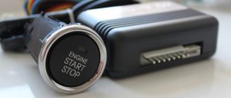
Driver's door switch button. Installation of the VAZ 2114 engine start button. Do-it-yourself installation.
Lada 2114 SnowMan › Logbook › Relocating the emergency gang
The reason for moving the panic button (hereinafter referred to as CAS) is due to two factors: 1) CAS, in my opinion, is located in a very inconvenient place. 2) The plans include installing a Kalina steering wheel and covers. Since there was no free space on my panel (there was only 1 plug left for the front PTF) for CORRECT CAS, I decided to install it instead of the cigarette lighter. I was very happy that the CAS cables were long enough for such a transmission and did not have to be increased. The appearance of the button itself, which looks more like a save button, didn’t really inspire me, so I decided to find an alternative to the stock button. That's what I liked.
— Alarm switch — 1 piece (110 rubles)
Since the place of the cigarette lighter was taken by CAS, and I often use it to charge my phone, I decided to install it to the right of the ashtray. To do this, it was necessary to drill a hole with a diameter of 29 mm. There was no drill of the required diameter, and I didn’t think cutting a hole with a round file was the best option. Having thought about what else you can do, you can make a hole with a large diameter, using circular type drills (crowns). The set includes a crown in the size I need.
Having made a hole, I processed the edges with a file and installed the cigarette lighter. The wire from the cigarette lighter was also enough, I didn’t save it.
Here's what I did.
Two positive points: 1) Now it has become more convenient to thank polite drivers (there is no chance of breaking your arm). 2) Charging a phone connected to the cigarette lighter no longer interferes with changing gears.
Since there was now a HUGE hole in the steering column housing due to the lack of UAS, it was necessary to drown it with something. Information has appeared on the Internet that a window regulator plug is suitable as a plug for this hole. I couldn’t find such a plug at the nearest auto store, but my eye fell on a rubber floor plug (it seemed to be the right size) that I bought.
— Floor plug 2108-5112090 large — 1 piece (16 RUR)
The cover with plug is installed (fits perfectly).
How to install the euro button?
To install a Euro-sample button instead of the factory installed one, you will need to purchase the following electronic components:
- Euro button for emergency lights VAZ 2114.
- Block for its installation.
- Relay type HLS4453.
- Block for the specified relay (it is possible without it, but blocking greatly simplifies assembly).
- Approximately 2 meters of wire with a cross section of about 0.5 square meters. Mm.
- Terminals in the amount of 6 pcs.
- Insulating tape.
The first thing to do is connect the new Euro button to the electronic relay.
This should be done according to the following scheme:
All wires going from the new button to the relay must be securely fastened (preferably soldered). And the terminals should be connected to the ends of the wires coming from the relay to the old button (or rather, to its block.
Despite the fact that the connection using terminals is quite strong, it is still recommended to solder it by applying a small amount of solder to the wire entry point - this will significantly increase reliability and improve contact.
After connecting the Euro 2114 emergency tape and relay, you will need to remove the old button. To do this, first unplug it from the socket and then disconnect it from the electronic lock. The block itself needs to be moved to the europanel (where the new button should be attached), then 6 terminals from the relay must be connected to it. This must be done according to the numbering of the wires coming out of the relay, which was shown in the diagram above.
On the block itself, if you place it with the empty slots down, the numbering will look like this (clockwise): 4-3-2-1-8-7.
Then we disconnect the side light button from its block and connect to it the wires coming directly from the button (indicated in the diagram). One goes to the size wire (it's white), the other goes to the negative wire (it's completely black). All connections must be well twisted and insulated. Next, we connect the size button to the block.
The last thing left to do before the Euro-crash on the VAZ 2114 is finally installed in its place is to remove one (any) plug on the Euro-panel, bring the lock connected to the system to it, and simply insert the button into it.
If your car has an on-board computer, it must be turned off before installing a new alarm button. There is no need to turn off other electronic devices.
Power button
PTF connection diagram for VAZ 2114 in good quality with description.
Sometimes the alarm system stops working due to the failure of its activation button. When removed, sometimes its defects are visually visible. In order for the light fixture to function again, the part will need to be replaced.
If trouble happens on the road, you can temporarily restore the functionality of the emergency lights without having to buy a new button. To do this, you will need to remove it and disconnect it from the block. Using a paper clip or wire, make a jumper that will close the contacts of the block. The part must be positioned so that the cutout on one of the faces is at the bottom. Insert the jumper into the middle socket in the left row of contacts. Secure its second end into the lower socket of the adjacent row. If everything is done correctly, the hazard warning lights and turn signals will work as normal.
Scheme for switching on headlights, side lights and turn signals for VAZ-2113, 2114 and 2115
Headlight switching diagram for VAZ-2113, 2114 and 2115
Ignition circuit for headlights and fog lights:
1 — block headlights; 2 — mounting block; 3 — headlight switch; 4 — ignition switch; 5 — external lighting switch (fragment); 6 — fog lights in the rear interior lights; 7 — fog light switch with warning lamp; 8 — indicator lamp for high beam headlights in the instrument cluster; K8 - high beam relay; K9 - relay for low beam headlights; A - the order of conditional numbering of plugs in the headlight block; B - to power supplies
Scheme for switching on the side lights of VAZ-2113, 2114 and 2115
Scheme for switching on external lighting:
1 — side lights in the headlights; 2 — engine compartment lamp; 3 — mounting block; 4 — engine compartment lighting switch; 5 — ignition switch; 6 — external lighting switch (fragment); 7 — indicator lamp for external lighting in the instrument panel; 8 — side lights and brake lights in the external rear lights; 9 — license plate illumination; 10 — instrument lighting regulator; 11 — brake light switch; 12 — blocking of the on-board control system; K4 - lamp status monitoring relay (contact jumpers are shown inside the relay, which should be installed if there is no relay); A - to power supplies;
Reworking the low beam button
It, like an abrasive, increases the friction force, which creates resistance to glass movement.
Installing PTF provides better illumination of the roadside and side markings, reducing the risk of leaving the road. Some motorists are of the erroneous opinion that fog lights with high lighting efficiency can only be yellow. These grooves tend to become clogged with dirt.
This allowed additional parts to be kept to a minimum and simplified the design.
A well-known situation arises - the blinding of drivers of oncoming vehicles, which increases the risk of an accident. This is due to the geometry of the lifting mechanism. Is this really true?
We recommend: Era switch how to connect
Manual window lifters
There are 8 clips installed around the entire perimeter of the door. Replacement cost Replacing VAZ window regulators is cheaper than installing electric mechanisms to replace manual ones.
They create fewer electrical problems, but the inconvenience of using them is that while in the driver's seat, it is impossible to open the window on the passenger side without being distracted from driving. The front left window regulator fails faster due to more frequent use.
Registration
Location of relays and fuses of the old model 1 - relay for turning on the headlight cleaner K6; 2 — rear window washer time relay K1; 3 - relay breaker for direction indicators and hazard warning lights K2; 4 — windshield wiper relay K3; 5 — contact jumpers in place of the relay for monitoring the health of the lamps; 6 — relay for turning on the heated rear window K10; 7 - spare fuse; 8 — relay for turning on the main beam headlights K5; 9 — relay for turning on the low beam headlights K11; 10 - fuse; 11 — relay for switching on the electric motor of the engine cooling system fan K9; 12 - relay for turning on the sound signal K8. In the cabin, in a place convenient for the driver, a button for turning on the PTF is installed. The grille with the speaker is removed from the standard front panel. To illuminate the central locking button 4. On the driver's door there is a block of buttons that control all windows that have an electrical connection for VAZ power windows
It consists of a roller and a gearbox, which is rotated either by a handle or by an electric motor if there is an electrical circuit for the VAZ window regulator. Fill the upper part of the resulting pads with silicone. The mentioned wires are pulled to the fuse block from the fog light relay. I have not yet figured out how to overcome this problem, so I have disabled the microswitch for now and use the central lock button. Absent 8. VAZ 2110,11,12 CONNECTION OF FRONT FOG LIGHTS ACCORDING TO STANDARD
https://youtube.com/watch?v=1blkkgGJwZg
Replacing the column casing
As already mentioned, when removing the old button from the steering column cover, a large hole remains in the latter. Of course, this will not interfere with the operation of the machine, but it is still better to replace the casing.
When choosing a new one (and you will have to take it from other VAZ models), you should consider the following points:
- presence of all necessary holes for control elements;
- their location;
- the size of the hole for the steering wheel (for example, on the casing for Kalina is very large).
The optimal one, according to reviews from car enthusiasts themselves, is a standard (not “euro”!) casing for the tenth model.
When do the hazard warning lights turn on?
Its use is mandatory in the following situations:
- if a traffic accident occurs;
- if you had to make a forced stop in a prohibited place, for example, due to a technical malfunction of your car;
- when in the dark you are blinded by a car coming towards you;
- Hazard lights also turn on when the vehicle is being towed;
- when boarding and disembarking a group of children from a specialized vehicle, it must be accompanied by an information sign - “Transportation of children.”
Hazard alarm as a “lifeline” in an unusual situation on the road
Today, all modern cars without exception are equipped with hazard warning lights (HAS). Its purpose is to warn other motorists about a vehicle malfunction, thus marking it on the road. In what cases is the emergency alarm button used and how this system works - read below.
Euro emergency warning button VAZ 2115
In the end, I decided to make a hazard button (or, more simply put, a "hazard strip") myself. In our Russian VAZ 2113-2115 it sits well in a very uncomfortable place. More precisely behind the wheel. And in the modern rhythm of life, when it has become customary to “blink” at the emergency lane as a sign of greeting or gratitude, such an arrangement is unacceptable.
I started by ordering “Relay HLS-4453 (18F) -4, DC12V, 4 groups of contacts. 5A "from the site www.ekits.ru/index.php?product >
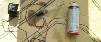
Then I bought 1.5 wires, many wrote that these are the only ones needed, but they are too large and 0.75 above the roof is enough. Bought, as in common parlance, “PPA” and electrical tape. So, a soldering iron in your hands and a diagram in front of your eyes.
Everything is quite simple, but you waste a lot of time, if you assemble it for the first time, then I assembled it from scratch in 3 hours)) Then INSTALLATION: I forgot to take most of the photos myself, so I took this from other users: www.drive2.ru/l/363984 / and www.drive2.ru / l / 1042092/
We disassemble the instrument panel and remove the casing.
We remove the casing and disassemble the old emergency tape button and move the wires to a place convenient for us.
We begin to slowly collect our miracle. We place the button where it will be most convenient for us to use it.
We assemble the wires from the new button to the old one according to the diagram.
Just in case, I tied it with electrical tape so that it would not fly out of the connectors on uneven surfaces. Then install the DIN rail into the empty space. And tighten it with nut and bolt 5.
We install the block with the relay on it.
And finally, let's start connecting to the dimensions and the dashboard itself.
I draw your attention to the fact that according to the diagram there are two drawbacks, they can be combined into one, but I made them 2 different and connected them to the size block, there are 2 black wires, both are drawbacks, I did both)) And the size The new one connected the buttons to the white wire on the block.
Next, let's move on to the toolbar itself. We unscrew it, it is secured with two self-tapping screws. At the back we see two contact pads, white and red, we need the red one and connect the wire there, which we go according to the diagram into an empty socket.
This is so that the red triangle lights up (you can do without it). Looks really cool. PS Some panels do not have a triangular backlight, you need to buy one and screw it on.
In the end, this is what my button looks like
It took me about 2 hours to install.
All you need for the euro button:
1. Relay HLS-4453 (18F) -4, DC12V, 4 groups of contacts. 5A — 106 rub. 2. Relay block HLS-4453 (18F) - 62 rubles. 3. Euro button - 91 rub. 4. Lock on the euro button - 50 rubles. 5. DIN rail - 7 rubles. 6. Dad - 7 pieces - 40 rub. (we buy 6 large and 1 small). 7. Wires 1.5 - 7 meters * 8.2 rub. = 58 rub. (I repeat, it’s better to take 0.75 threads and 7 meters was not enough for me, take 8 meters). 8. Electrical tape - 15 rubles.
Recommendations
Comments 50
The other day I installed the same button from VAV-21123. I didn't connect the indicator. The wiring marked “Dimensions” is also not connected anywhere, but the emergency lights are working (all turn signals and repeaters are blinking, the arrows on the dash are blinking, the light in the button is blinking, there is a clicking sound). What is this wiring for (“Dimensions”)?
Then some miracles began. The day before yesterday the following happened several times: arbitrary single clattering of the turn signal while driving (the sound was heard, but I did not notice whether the turn indicator (arrow) was blinking), as well as some kind of grinding noise (as if it was shorting) after turning off the turn signal (had to several times pull the handle back and forth to make it disappear). This happened several times.
Yesterday all this no longer happened, but on one of the turns the car simply passed out - it stalled, but continued to roll. Turned the ignition off and on - it started and drove on. Today this happened again while overtaking, blinking in the other direction. It feels like it was switched off when the turn signal was turned on.
Whether all these events are related to the installation of a new button, or whether it was a coincidence, I don’t know, but it’s disturbing in any case.
>> What is this posting (“Dimensions”) for? In order for the button illumination indicator to glow green when the side lights are turned on)) Most likely a coincidence (I’m talking about a stalled engine). But what is clicking... maybe something is wrong with the relay or the power supply to pin 13 of the relay.
Since then there haven’t been any more such quirks - apparently the button has caught on
Auto-assistance
The panic button of the VAZ-2115 car simultaneously turns on all turn signals through the same relay K2 as under the steering turn signal switch. This electrical circuit receives only power from another fuse (F2, not F16, as in turn signals), located under the hood of the car in the mounting block.
Therefore, in principle, there are two main options for failure of the alarm system: either it does not want to turn on itself and the turn signals work, or both of these electrical circuits do not work at the same time. In the first case, you will have to look for a fault in the mounting block and the panic button, and in the second, check the functionality of the K2 relay.
Troubleshooting the “emergency tape” in the mounting block of a VAZ-2115 car begins with checking the 10-amp fuse F2. If it burns out, you need to look for the reason for its failure, usually this is a short circuit in the electrical circuit it protects. Inserting a new fuse without finding a short one does not make much sense, since it will also burn out.
It also happens that fuse F2 is intact. Then, using a test lamp or tester, you need to check whether voltage is supplied to its terminals. If there is no voltage, you will need to check whether voltage is supplied to pin 3 of block X1 of the mounting block, since this is where the plus is supplied from pin 15 of the ignition switch. If there is voltage at the 3rd pin, we can conclude that there is an open circuit on the mounting block board from pin 3 of the X1 block to the fuse pin F2.
If fuse F2 is working and there is voltage at its terminals, remove the panic button from the front panel, turn off the unit and check the voltage at pin 2 of this unit, naturally, with the panel turned on. If there is voltage at pin 2, the culprit for the alarm failure will be its power button, which will need to be replaced. And if there is no voltage at pin 2, the wire from pin 2 of the alarm unit to pin 3 of connector X4 of the mounting block will need to be “ringed.”
If the alarm does not work together with the direction indicators, you will need to check relay K2. The easiest way to check is to install in its place exactly the same relay, but one that is repairable.
Instructions for repairing and replacing turn signals and hazard warning lights with your own hands
VAZ 2114 button connection diagram
Before removing and replacing failed lighting devices with white or yellow ones, you must turn off the ignition and battery. This will avoid short circuits. Replacement work must be carried out with gloves to avoid staining the glass of the light bulbs.
How to change lamps in software:
- First you need to disconnect the connector with the connected wires from the optics.
- Then the spring tip is released.
- Now press on the mount located between the optic and the rotation. Remove the block with the software light source from the seat.
- Bulbs that are not working are replaced and reassembled in the reverse order.
- As for the repeaters, to replace, remove its body from the seating location along with the rubberized gasket, about half a centimeter forward.
- Remove the back of the device from the installation location.
- Remove the repeater completely, then disconnect the plug and wiring and remove the gasket. After this, the gasket itself must be installed on the new repeater.
- Now all that remains is to reconnect the plug with the wiring and install the repeater back.
Troubleshooting Methods
There are two methods for detecting faults:
Ignition switch circuit
We suggest studying a visual method for determining a malfunction or breakdown of the contact elements of the ignition switch using the table.
To work, you will need a mini-tester and a multimeter in ohmmeter mode:
- Disconnect the power unit from the ignition switch. To do this, you need to remove the trim from the steering column;
- Change the multimeter to an ohmmeter;
- On the block coming from the lock, you need to find contacts 7 and 4, corresponding to contacts 15 and 30;
- Connect the multimeter probes to them;
- Turn the key to the “Ignition” position;
- Find pins 7 and 3 on the block, corresponding to 50 and 30. Also connect a multimeter to them;
- Turn the key to the second position - start the engine;
- If there is a fault, the meter will show zero resistance in both test cases.
Mass air flow sensor VAZ 2114
The mass air flow sensor is necessary for efficient engine operation in several modes. The function of this device is to create a working mixture of air and gasoline vapor. The task of the VAZ 2114 air flow sensor is to measure two related indicators:
- Amount of air consumed;
- Response time.
The accuracy of measuring the engine air flow allows the controller to determine in what proportion to mix air with fuel. If the sensor produces incorrect values, the resulting air-fuel mixture does not correspond to the current engine operating mode. This leads to a decrease in power, an increase in fuel consumption, and a deterioration in the dynamics and responsiveness of the car. The response of controllers from different manufacturers to these parameters may differ.
For example, January-5.1, in case of slight overestimation or underestimation of values, determines the error of the mass air flow sensor based on the readings of the oxygen sensor, thereby adjusting the duration of fuel injection. Increasing the sensor response time will result in the controller not keeping up and at the time of acceleration you will notice “dips” of the engine. The same sensor failure when using a more sensitive Bosch controller will result in a hesitant idle, although there will be no noticeable dips during acceleration.
Sources
- https://CarsUp.ru/obzory/knopka-avarijki-2114.html
- https://skolkogramm.ru/info/shema-podklyucheniya-evro-knopki-avarijki-vaz-2114
- https://delis-avto.ru/obzory/raspinovka-avarijki-vaz-2114.html
- https://RusBrat.ru/to-i-remont/knopka-avarijnoj-signalizacii-vaz-2114.html
- https://aist-studio.ru/remont/knopka-avarijki-vaz-2114.html
- https://novoname.ru/knopka-avariyki-vaz-2114-obzor-i-varianty-zameny/
- https://AVSU-pitanie.ru/info/shema-podkljuchenija-evro-knopki-avarijki-vaz-2114/
- https://StopMod.ru/remont-i-tyuning/evro-avarijka-2114-shema-podklyucheniya.html
- https://artel55.ru/obzory-i-testy/knopka-avarijki-vaz-2115.html
- https://gt-models.ru/novosti/knopka-avarijki-vaz-2114.html