There are several different types of engines, and in wheeled, tracked, water and sometimes even air transport (trucks and cars, special equipment, motor boats, airplanes, etc.), you can often find an internal combustion engine (ICE).
Internal combustion engines are gasoline and diesel, and can also successfully run on gas and even hydrogen (hydrogen internal combustion engine). Motors also differ in design and layout; they are two-stroke and four-stroke.
One way or another, a power unit of this type has become widespread due to its autonomy, versatility, as well as a number of other advantages. At the same time, the units have many different parameters and characteristics, among which it is worth highlighting the operating cycle. Next, we'll talk about what the duty cycle of an automobile internal combustion engine means.
What is a 2 stroke motor?
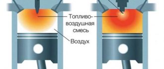
A 2-stroke engine is a type of piston engine in which the working process is completed in two strokes of the piston. Such an engine has only 2 strokes, a compression stroke and a power stroke. Moreover, cleaning and filling the cylinder with the combustible mixture is carried out not in separate strokes, as in a 4-stroke engine, but in joint ones.
Interesting materials:
How to make Arabic numerals on a laptop? How to record screen on Samsung M31? How to block only unknown numbers on Samsung? How to rotate the screen on Samsung? How to take a screenshot on a Sony Xperia? How to take a screenshot on your DXP phone? How to take a screenshot of an area of the screen on Windows 10? How to make the screen brighter on Windows? How to make a flash on Xiaomi when there is a call? How to write an application to build a children's playground?
How does a four stroke engine work?
Structurally, the working cycle of a typical four-stroke unit is ensured by the operation of the following elements:
- cylinder;
- piston - performs reciprocating movements inside the cylinder;
- intake valve – controls the process of supplying the air-fuel mixture to the combustion chamber;
- exhaust valve – controls the process of exhaust gases expelling from the cylinder;
- spark plug – ignites the resulting air-fuel mixture;
- crankshaft;
- camshaft - controls the opening and closing of valves;
- belt or chain drive;
- crank mechanism - translates the movement of the piston into rotation of the crankshaft.
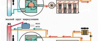
Operating cycle of a four-stroke engine
The operating cycle of such a mechanism consists of four strokes, during which the following processes are implemented:
- Intake (fuel and air injection). At the beginning of the cycle, the piston is at TDC. At the moment when the crankshaft begins to rotate, it acts on the piston and moves it to BDC. This leads to the formation of vacuum in the cylinder chamber. The camshaft acts on the intake valve, gradually opening it. When the piston is in its extreme position, the valve is completely open, resulting in intense injection of fuel and air into the cylinder chamber.
- Compression (increasing the pressure of the combustible mixture). In the second stage, the piston begins to move back to the top dead center of the compression stroke. The crankshaft makes another turn and both valves are completely closed. The internal pressure increases to 1.8 MPa and the temperature of the combustible mixture rises to 600 C°.
- Expansion (working stroke). When the piston reaches the top position in the combustion chamber, the maximum compression is set to 5 MPa and the spark plug is fired. This leads to combustion of the mixture and an increase in temperature to 2500 C°. Pressure and temperature lead to an intense impact on the piston, and it begins to move back to BDC. The crankshaft makes another turn, and thus the thermal energy is converted into useful work. The camshaft opens the exhaust valve, and when the piston reaches BDC, it is fully open. As a result, the exhaust gases begin to gradually leave the chamber, and the pressure and temperature decrease.
- Exhaust (removal of exhaust gases). The engine crankshaft turns and the piston begins to move to the top point. This leads to the expulsion of exhaust gases and an even greater decrease in temperature and a decrease in pressure to 0.1 MPa. Next, a new cycle begins, during which these processes are repeated again.
During each stroke, the engine crankshaft rotates 180°. During a full working cycle, the crankshaft rotates 720°.
The four-stroke engine has become widespread. It can work with both gasoline and diesel fuel. The difference between the operating cycle for a diesel engine is that the ignition of the air-fuel mixture does not occur from a spark, but from high pressure and temperature at the end point of the compression stroke.
What are the main differences?
Features of operation require consideration first in order for the comparison to be correct:
- In diesel engines, the air-fuel mixture is formed much faster when compared to a unit running on gasoline. In the cylinders of such engines, only air is compressed, the temperature of which corresponds to approximately 900 degrees. Gasoline is supplied separately to the compartment for subsequent combustion. Small fragments of diesel fuel evaporate at an accelerated rate and combine with the air mass. Due to the sufficiently high temperature effect, the resulting mixture is easily ignited without the need for ignition with a spark. Such engines consume significantly less oil.
- Air and fuel in gasoline engines are combined in a specially designed exhaust manifold, after which the fuel enters the compartment for further combustion. When the compression stroke is completed, the final stage of formation of the fuel-air composition is completed and its subsequent distribution throughout all compartments of the cylinder. After squeezing, the resulting mixture reaches a temperature of approximately 500 degrees, and then the procedure of igniting it using a candle is performed.
Origin information
When choosing a name for a child, parents can pay attention to every detail. They are interested not only in what impact this or that way of naming the baby will have on the fate
The history of the name, existing versions of its origin and even rarity of use come into the field of attention.
There are several versions about the origin and meaning of the name Eliana. Among them, three main ones stand out. Each offers its own interpretation of where this female name came from.
The first is based on the Roman origin and meaning of the name Eliana. History says that it was formed from the generic or personal nickname Aelianus. In turn, this nickname takes its roots from the Greek word “helios”. In this case, the name carries the meaning of “sunny”, which makes it somewhat related to Elena.
The second version indicates that the name Eliana is of Jewish origin. In this version, the translation sounds like “God answered me” or “my God is my family.”
The third version of where the meaning of the name Eliana comes from is French. According to this theory, the word has two translations. The first sounds like “daughter of the sun,” which overlaps with Greco-Roman theory. In the second version - as “good day”.
Design features
In addition to differences in operating principles, these motors also have design features.
The 2-stroke engine is structurally simpler. The gas distribution mechanism is an additional engine equipment that complicates the design.
A 2-stroke engine does not have this mechanism and its role is played by the piston, opening and closing certain windows.
In addition, this engine does not require a lubrication system. This is due to the fact that the under-piston space, where the knees are located, is also involved in the work process. shaft.
But since the crank mechanism requires lubrication, in this engine it is produced together with fuel, that is, engine oil is added to the fuel, and when fuel enters this space, the existing oil lubricates the mechanism.
For 4-stroke engines, the design includes both a gas distribution mechanism and a separate lubrication system.
This significantly complicates the design, however, these engines are a higher priority than two-stroke engines due to a number of operational shortcomings of the latter.
Content
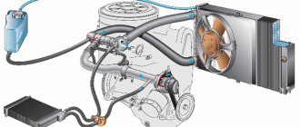
A heat engine is a machine that converts internal energy into mechanical energy. The simplest model of such a machine can be imagined as a metal cylinder and a tightly fitting piston that can move along the cylinder.
One of the most common types of heat engine that we encounter in life is the internal combustion engine (ICE) . The fuel in it burns directly in the cylinder, inside the engine itself. It's easy to guess that this is where its name comes from.
In this lesson we will look at the design of an internal combustion engine and its operation diagram.
Expanded classification of thermometers
Let us make a reservation that in the framework of the review we will not separate pyrometers from the topic. This is a slightly different class of devices, actively used for similar purposes as temperature sensors. So, it is customary to distinguish:
Expansion thermometers. Based on the ability of bodies to change geometric dimensions:
- Glass liquid thermometers are outside the window. Already considered temperature sensors. Mercury is most often used as a liquid for a number of reasons: it retains its state of aggregation in a wide range of environmental conditions, does not wet glass, and is easily extracted from natural components. Disadvantages include toxicity, low coefficient of thermal expansion and solidification even at minus 35 degrees Celsius. This reminds us of the benefits of alcohol thermometers.
- Manometric thermometers are based on the dependence of the vapor pressure of a substance in the working chamber on temperature. Such systems are readily used as thermostats in old refrigerators that do not have electronics. Pros: the system does not require electrical power, which greatly simplifies the design of the device. These temperature sensors are located in the evaporator area and are connected through a tube to the regulator (located in the refrigeration compartment), where the relay is located.
Thermometric sensors and resistance thermometers include thermocouples and thermistors. This is a hackneyed topic, we’ll touch on it a little lower. Metals, semiconductors, and other classes of the periodic table are used as materials for these temperature sensors.
Resistance thermometer
Operation - Duty Cycle
| Diagram of the filtration plant at the Kalmius Central Processing Plant.| Filter installation. |
The work cycle operations are regulated automatically using a time relay, without the use of manual labor.
Each operation of the work cycle is specified by one command.
The four operations of the working cycle are automatically controlled by a time relay. Typically, calculating a material balance requires about 30 cycles, during which time it is possible to collect cracking products in quantities sufficient to determine all components. The temperature is regulated by automatic point devices (regular pockets are used to insert thermocouples) and is automatically recorded. Each reactor has two thermocouples installed in the lower and upper zones of the catalyst bed. Temperature measurements at these two locations indicate whether the catalyst bed is sufficiently mixed.
Of all the operations in the centrifuge operating cycle, the most power consumed is Unloading. In this case, the power is spent on overcoming the forces of inertia and adhesion of particles of the rotating layer of sediment, directed by the cutting mechanism for unloading. The lowest load is observed during the Drying operation, when power is spent mainly on ventilation losses and to a small extent on friction in the bearings.
| Hydraulic and kinematic diagrams of the moving and turning mechanisms of excavators. |
Thanks to this, all operations of the working cycle are controlled using two handles located on both sides of the steering wheel in the range of the driver’s hands. The design of the handles allows you to move them not only back and forth and left and right, but also in any other direction. When the lever moves diagonally, two hydraulic valve spools are simultaneously activated and the two working movements in the cycle are combined in time.
| Block diagram of indexing of single-bucket universal excavators. |
The working process of an excavator includes the operations of the work cycle and the operation of moving the machine, which is carried out after it becomes impossible or inconvenient to excavate the soil from the parking lot.
Depending on the sequence of operations of the working cycle, the loading process of the engine of a single-bucket excavator is formed. The methods outlined in the specialized literature make it possible to determine the average power removed from the engine crankshaft during each operation of the operating cycle.
It has a number of devices that allow you to automate most of the operations of the working cycle, in particular the supply of pipes to the inspection area, its rotation during the inspection process and the removal of the pipe after the end of the inspection to the rack.
Machines of this type are characterized by continuous rotation, frequency of work cycle operations and automation of these operations. Loading the centrifuge, the jointing process itself, washing, removing and unloading the sediment are carried out strictly periodically, at certain intervals; they also continue for a certain time and are controlled by a special automation system that manages and controls all operations. The worker's functions are reduced solely to starting the machine, which can then work without stopping for an indefinitely long time.
Advanced crane operators widely combine crane operating cycle operations when loading and unloading containers. Simultaneously with the movement of the container in the transverse or longitudinal direction, the container is raised or lowered to a height that ensures the safety of further movement. When operating gantry and overhead cranes, just like when operating jib cranes, a combined loading and unloading method is used. To combine individual operations in the work cycle, it is advisable to use the method of parallel processing of platforms and vehicles. To do this, cars approach certain areas, and the crane, moving along the front, simultaneously processes the platforms and cars. The downtime of individual vehicles is increasing slightly, but the average downtime of vehicles at the container site is decreasing.
Branch broaching can be done with one or three cores. All operations of the working cycle - loading, supply of blank pipes, removal of bends from the core - are carried out mechanized.
By introducing the method of Stalin Prize laureate F.L. Kovalev into excavation work, one can achieve great success in increasing the productivity of the machine. Different Stakhanovites perform the operations of the excavator working cycle using different techniques, so the duration and effectiveness of these operations are not the same for different excavator operators. Kovalev allows you to select, study and implement only the best techniques of the Stakhanovites and thereby achieve the greatest productivity.