Operation of sensors in VAZ injection and carburetor engines: table of typical parameters
Optimal operation of a car engine depends on many parameters and devices. To ensure normal operation, VAZ engines are equipped with various sensors designed to perform different functions. What you need to know about diagnosing and replacing controllers and what are the parameters of sensors for VAZ injection engines is presented in the table in this article.
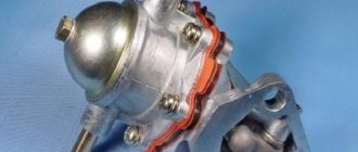
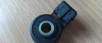
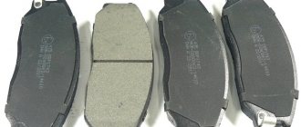
Understanding the oxygen sensor
It is necessary to determine the sensor articles not by the engine model or even by Euro standards, but only by the ECU unit. The number of oxygen sensors can be two or one - it all depends on environmental standards. AvtoVAZ also used two types of sensors - 0 258 005 133, 0 258 006 537 (BOSCH part numbers). The first of them are compatible with BOSCH M1.5.4, MP7.0 and January 5.1 controllers. Newer sensors were connected to the BOSCH M7.9.7 ECU (January 7.2). The two different types of sensors differ even in appearance. The ECU unit in “Dozens of VAZs” is located under a plastic cover. It is located near the front passenger's foot. The red arrow marks the first, that is, the main sensor. The top photo corresponds to engine 21124 (1.6 l). VAZ-21120 engines (1.5 l) could meet the Euro-3 standard, and then an “extended” catalyst was welded behind the main sensor. The second sensor was located behind it, that is, behind the “can”. Let's clarify:
- The Euro-2 standard corresponds to a design with one sensor (main);
- During the transition to Euro-3 standards, a second sensor was added (blue arrow).
By the way, the 24th engine can meet Euro-4 standards.
Typical operating parameters of VAZ injection engines
Checking VAZ sensors is usually carried out when certain problems are detected in the operation of the controllers. For diagnostics, it is advisable to know what malfunctions of VAZ sensors can occur; this will allow you to quickly and correctly check the device and replace it in a timely manner. So, how to check the main VAZ sensors and how to replace them after that - read below.
Basic parameters of controllers on VAZ injection engines
DIY diagnostics of Lada Kalina 1, 2
Diagnostics by car models April 2, 2022 Rating:
Reading time
Difficulty of the material:
For the pros - 4 out of 5
To independently carry out computer diagnostics of the Lada Kalina via a laptop or smartphone, just connect to the OBD2 connector with a diagnostic adapter and a car scanner. In 90% of cases, comp. Auto diagnostics boils down to reading data from the ECU, but not every driver knows how to do this correctly.
This manual describes in detail the process of connecting to the “brains” of the car, including which auto scanner and program to choose. In the article you will find many useful links to more detailed instructions and site materials.
Author of the site elm327-obd2.ru
Features, diagnostics and replacement of elements of injection systems on VAZ cars
Below we will look at the main controllers!
Hall
There are several options for how you can check the Hall sensor of a VAZ:
The replacement procedure is performed as follows (the process is described using the example of model 2107):
Speeds
The following symptoms may indicate a failure of this regulator:
Fuel level
The VAZ or FLS fuel level sensor is used to indicate the remaining volume of gasoline in the fuel tank. Moreover, the fuel level sensor itself is installed in the same housing with the fuel pump. If it malfunctions, the readings on the dashboard may be inaccurate.
The replacement is done like this (using the example of model 2110):
Photo gallery “Changing the FLS with your own hands”
Idle move
If the idle speed sensor on a VAZ fails, this is fraught with the following problems:
To solve the problem of device inoperability, the VAZ idle speed sensor can either be cleaned or replaced. The device itself is located opposite the cable that goes to the gas pedal, in particular, on the throttle valve.
The VAZ idle speed sensor is fixed using several bolts:
Crankshaft
The VAZ crankshaft sensor is used to synchronize the operation of the fuel supply and ignition systems. Diagnosis of DPKV can be made in several ways.
To replace the DPKV, do the following:
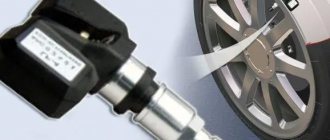
Lambda probe
The VAZ lambda probe is a device whose purpose is to determine the volume of oxygen present in the exhaust gases. This data allows the control unit to correctly create the proportions of air and fuel to form a combustible mixture. The device itself is located on the exhaust pipe of the muffler, at the bottom.
The regulator is replaced as follows:
Test sequence
To check the mass air flow sensor with a multimeter, you will need skills in using the tester itself. The technique is suitable for many VAZ models. Thus, if you understand the basic principle, you can understand how to check the mass air flow sensor of a VAZ 2114 or mass air flow sensor 116. This also applies to the Bosch PBT-GF30 device. First of all, the tester is set to a mode that measures constant voltage. To work, first study the pinout. In different models, the colors of the wires sometimes differ, but their sequence does not change.
VAZ 2107
How to check the MAF sensor with a multimeter? To inspect the electrical circuit, you cannot do without pinouting the SIEMENS VDO contacts. First of all, check the block located on the side of the electronic control unit. To do this, you will need to secure the negative wire of the multimeter to ground.
Then the ignition is turned on, and the positive one is connected to contact No. 5 of the block: the normal voltage is 12 V. The sequence of actions is repeated with contact No. 4 (the norm is 5 V). If the numbers are different, it is worth checking the ECU.
It is also worth considering that a decrease in voltage in the VAZ 2107 mass air flow sensor can occur due to corrosion processes.
VAZ 2110
How to check the mass air flow sensor with a multimeter? Detailed information about this is written in the instructions. But if you know where the grounding is located, as well as the wiring of the incoming signal, the master will do without a book with instructions for the mass air flow sensor on the VAZ 2110. Then they turn on the ignition and do not start the engine. Next, the limit mark of 2 V is set on the multimeter. After this, the probe of the device is connected to the green ground wire, the red wire is connected to the yellow one.
The probes are placed with care, without an additional needle, so as not to damage the insulation. Then, when checking 2110 with a multimeter, look at the screen. With a new consumable, the voltage will be 1.01. The values gradually increase as the resistors of the mass air flow sensor on the VAZ 2110 wear out. If the number increases, the air flow sensor VAZ 2110 8 valves are increasingly subject to wear.
VAZ 2112
The mass air flow sensor on a VAZ 2112 is easy to check. During diagnostics, you will need to disconnect the chips from the power supply and insert the probes of the device. When it starts in emergency mode, oxygen will be dosed according to the latest values. When the power does not close when starting the motor, most likely the problem is in the device itself.
VAZ 2114
How to check the air flow sensor of a VAZ 2114? To check the VAZ 2114 air flow sensor using a tester, perform the following procedure:
- First of all, the multimeter should work in measuring mode up to 20 V.
- Then connect the red wire to pin No. 5, the black wire to pin No. 3.
- After this, turn the ignition (but do not start the car) and look at the display.
This is a brief description of how to check the mass air flow sensor on a VAZ 2114.
VAZ 2115
To begin with, it is worth preparing the measuring device according to the example described in the previous subsections. Then, on the VAZ 2115, operations are performed step by step: the black end of the tester is connected to contact No. 3, and the red end to No. 5. You can connect them with a pin. The next step is to turn the ignition without starting the vehicle. After this, information will appear on the display.
It is important to check in a timely manner how the mechanism works. In some cases, a complete diagnosis may be necessary at a service center using high-precision equipment.
The service center will carry out repairs, carry out cleaning, and, if necessary, replace faulty devices with new ones.
Motorhelp.ru engine diagnostics and repair
Typical operating parameters of VAZ injection engines.
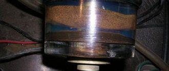
1.3 MAF ADC channel in rest mode: 0.996/1.016 V - normal, up to 1.035 V is still acceptable, everything above is already a reason to think about replacing the mass air flow sensor. Injection systems equipped with feedback from an oxygen sensor are able to correct, to some extent, incorrect readings of the mass air flow sensor, but there is a limit to everything, so you should not delay replacing this sensor if it is already worn out.
2. The engine is idling.
2.1 Idle speed. Typically this is 800 - 850 rpm with a fully warmed up engine. The idle speed value depends on the engine temperature and is set in the engine control program.
2.2 Mass air flow. For 8-valve engines, the typical value is 8-10 kg/h, for 16-valve engines - 7-9.5 kg/h with a fully warmed-up engine at idle. For the M73 ECU these values are slightly higher due to a design feature.
2.3 Length of injection time. For phased injection, the typical value is 3.3 - 4.1 ms. For simultaneous – 2.1 – 2.4 ms. Actually, the injection time itself is not as important as its correction.
2.4 Injection time correction factor. Depends on many factors. This is a topic for a separate article, but it’s worth mentioning here that the closer to 1,000 the better. More than 1,000 means the mixture is further enriched, less than 1,000 means it is leaner.
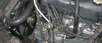
All VAZ-2112 sensors 16 valves and their location: diagram and description
The efficient operation of the injection engine is ensured by a set of sensors. They all connect to the ECU. Lada hatchbacks of the 2112 family were produced only with injection engines, and two varieties of these internal combustion engines are 16-valve. We will talk about them further. All VAZ-2112 sensors, their location and appearance will be shown in the photo.
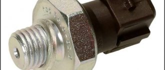
The excess oil pressure sensor, which is not connected to the ECU, is shown in the video.
Types of ECU (esud, controller). What kind of ECUs are installed on VAZ?
"January-4", "GM-09"
The very first controllers on SAMARA were January-4, GM - 09. They were installed on the first models before the year 2000. These models were produced both with and without a resonant knock sensor.
The table contains two columns: 1st column – ECU number, second column – brand of “brains”, firmware version, toxicity standard, distinctive features.
VAZ 2113-2115 from 2003 are equipped with the following types of ECUs:
"January 5.1.x"
Interchangeable with “VS (Itelma) 5.1”, “Bosch M1.5.4”
"Bosch M1.5.4"
The following types of hardware implementation are distinguished:
"Bosch MP7.0"
As a rule, this type of controller is released onto the market and installed at the factory in a single volume. Has a standard 55-pin connector. Capable of working with recrossing on other types of ECM.
"Bosch M7.9.7"
These brains began to be part of the car at the end of 2003. This controller has its own connector, which is incompatible with connectors produced before this model. This type of ECU is installed on VAZ with EURO-2 and EURO-3 toxicity standards. This ECM is lighter weight and smaller in size than previous models. There is also a more reliable connector with increased reliability. They include a switch, which will generally increase the reliability of the controller.
This ECU is in no way compatible with previous controllers.
"VS 5.1"
The following types of hardware implementation are distinguished:
"January 7.2."
This type of ECU is made with a different type of wiring (81 pins) and is similar to Boshevsky 7.9.7+. This type of ECU is produced both by Itelma and Avtel. Interchangeable with Bosch M.7.9.7. As for the software, 7.2 is a continuation of January 5th.
This table shows variations of the BOSCH ECU, 7.9.7, January 7.2, Itelma, installed exclusively on the VAZ 2109-2115 with a 1.5L 8kL engine.
| 2111-1411020-80 | BOSCH, 7.9.7, E-2, 1.5 l, 1st ser. version |
| 2111-1411020-80h | BOSCH, 7.9.7, E-2, 1.5 l, tuning version |
| 2111-1411020-80 | BOSCH,7.9.7+, E-2, 1.5 l |
| 2111-1411020-80 | BOSCH,7.9.7+, E-2, 1.5 l |
| 2111-1411020-30 | BOSCH,7.9.7, E-3, 1.5 l, 1-gray. version |
| 2111-1411020-81 | January 7.2, E-2, 1.5 l, 1st version, unsuccessful, replace A203EL36 |
| 2111-1411020-81 | January 7.2, E-2, 1.5 l, 2nd version, unsuccessful, replace A203EL36 |
| 2111-1411020-81 | January 7.2, E-2, 1.5 l, 3rd version |
| 2111-1411020-82 | Itelma, dk, E-2, 1.5 l, 1st version |
| 2111-1411020-82 | Itelma, dk, E-2, 1.5 l, 2nd version |
| 2111-1411020-82 | Itelma, dk, E-2, 1.5 l, 3rd version |
| 2111-1411020-80 h | BOSCH, 7.9.7, without DC, E-2, din, 1.5 l |
| 2111-1411020-81 h | January 7.2, without dc, with, 1.5 l |
| 2111-1411020-82 h | Itelma, without dc, with, 1.5 l |
Below is a table with the same ECUs, but for 1.6l 8kl engines.
| 21114-1411020-30 | BOSCH, 7.9.7, E-2, 1.6 l, 1st gray, (buggy software). |
| 21114-1411020-30 | BOSCH, 7.9.7, E-2, 1.6 l, 2nd gray |
| 21114-1411020-30 | BOSCH, 7.9.7+, E-2, 1.6 l, 1st gray |
| 21114-1411020-30 | BOSCH, 7.9.7+, E-2, 1.6 l, 2nd gray |
| 21114-1411020-20 | BOSCH, 7.9.7+, E-3, 1.6 l, 1st gray |
| 21114-1411020-10 | BOSCH, 7.9.7, E-3, 1.6 l, 1st gray |
| 21114-1411020-40 | BOSCH, 7.9.7, E-4, 1.6 l |
| 21114-1411020-31 | January 7.2, E-2, 1.6 l, 1st series - unsuccessful |
| 21114-1411020-31 | January 7.2, E-2, 1.6 l, 2nd series |
| 21114-1411020-31 | January 7.2, E-2, 1.6 l, 3rd series |
| 21114-1411020-31 | January 7.2+, E-2, 1.6 l, 1st series, new hardware version |
| 21114-1411020-32 | Itelma 7.2, E-2, 1.6 l, 1st series |
| 21114-1411020-32 | Itelma 7.2, E-2, 1.6 l, 2nd series |
| 21114-1411020-32 | Itelma 7.2, E-2, 1.6 l, 3rd series |
| 21114-1411020-32 | Itelma 7.2+, E-2, 1.6 l, 1st series, new hardware version |
| 21114-1411020-30 h | BOSCH, dk, E-2, din, 1.6 l |
| 21114-1411020-31 h | January 7.2, without dc, with, 1.6 l |
"January 5.1"
All types of controllers of their type are built on the same platform and most often have differences in the switching of injectors and the DC heater.
Let's look at the following example of ECU firmware January 5.1: 2112-1411020-41 and 2111-1411020-61. The first version has phased injection and an oxygen sensor, the second version differs only in that it has parallel injection. Conclusion - the difference between the ECU data is only in the firmware, so they can be interchanged.
Wrong name – January 7.3. This is the last type of controller that is currently installed at AvtoVAZ. This type of ECU has been installed since 2007. on a VAZ with EURO-3 toxicity standard.
The manufacturers of this ECU are two Russian companies: Itelma and Avtel. Below, the table shows ECUs for engines with EURO-3 and Euro-4 toxicity standards.
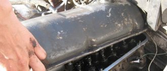
Characteristics of internal combustion engine 21124
The designers were not faced with the task of increasing power; it was much more important to increase the environmental standard, and to get rid of the danger of damage to the valves by the pistons if the timing belt breaks, so the engine layout remained unchanged:
- 16 valves;
- two overhead camshafts according to the DOHC scheme;
- belt drive of the gas distribution mechanism;
- 82 mm cylinder diameter.
As a result of design changes, the technical characteristics of motor 21124 are as follows:
| Manufacturer | AvtoVAZ |
| Engine brand | 21124 |
| Years of production | 2004 – … |
| Volume | 1599 cm 3 (1.6 l) |
| Power | 65.5 kW (89.1 hp) |
| Torque moment | 131 Nm (at 3500 rpm) |
| Weight | 121 kg |
| Compression ratio | 10,3 |
| Nutrition | injector |
| Motor type | in-line |
| Injection | distributed electronically controlled |
| Ignition | modular type |
| Number of cylinders | 4 |
| Location of the first cylinder | TVE |
| Number of valves on each cylinder | 4 |
| Cylinder head material | aluminum alloy |
| Intake manifold | combined with receiver, polymer |
| An exhaust manifold | catalyst |
| Camshaft | 2 pcs., marks on pulleys are offset by 2 degrees |
| Cylinder block material | cast iron |
| Cylinder diameter | 82 mm |
| Pistons | original, hole depth 5.53 mm |
| Crankshaft | from 11183 |
| Piston stroke | 75.6 mm |
| Fuel | AI-92-98 |
| Environmental standards | Euro 4 |
| Fuel consumption | highway – 6.4 l/100 km combined cycle 7.5 l/100 km city – 8.9 l/100 km |
| Oil consumption | maximum 0.5 l/1000 km |
| What kind of oil to pour into the engine by viscosity | 5W-30 and 10W-30 |
| Which engine oil is best by manufacturer | Liqui Moly, LukOil, Rosneft, Mannol, Motul |
| Oil for 21116 according to composition | synthetics, semi-synthetics |
| Engine oil volume | 3.5 l |
| Operating temperature | 95° |
| Motor life | declared 150,000 km actual 250,000 km |
| Adjustment of valves | hydraulic compensators |
| Cooling system | forced, antifreeze |
| Coolant quantity | 7.8 l |
| water pump | TZA |
| Candles for 21124 | BCPR6ES from NGK or domestic AU17DVRM |
| Gap between spark plug electrodes | 1.1 mm |
| Timing belt | Dyco, width 22 mm, service life 40,000 km |
| Cylinder operating order | 1-3-4-2 |
| Air filter | Nitto, Knecht, Fram, WIX, Hengst |
| Oil filter | catalog number 90915-10001 replacement 90915-10003, with check valve |
| Flywheel | from 2110 |
| Flywheel mounting bolts | box MT – M10x1.25 mm, length 26 mm, groove 11 mm box AT – M10x1.25 mm, length 26 mm without groove |
| Valve stem seals | code 90913-02090 inlet light code 90913-02088 exhaust dark |
| Compression | from 12 bar, difference in adjacent cylinders maximum 1 bar |
| XX speed | 800 – 850 min -1 |
| Tightening force of threaded connections | spark plug – 31 – 39 Nm flywheel – 62 – 87 Nm clutch bolt – 19 – 30 Nm bearing cap – 68 – 84 Nm (main) and 43 – 53 (rod) cylinder head – three stages 20 Nm, 69 – 85 Nm + 90° + 90° |
The presence of several repair sizes of cylinder liners and pistons ensures that major repairs can be carried out several times without replacing the cylinder block. That is, in accordance with the terminology accepted in engine building, motor 21124 conventionally refers to the “million-dollar” engine, and the manual includes not only a description of the parameters, but also step-by-step repairs of individual components.
How to deceive the mass air flow sensor using ECU firmware
The good thing about the previous method is that its implementation does not require complex equipment or painstaking work. If you were able to check the voltage at the output of the flow meter with a multimeter (which means you at least have one), and know how to hold a soldering iron in your hands, installing a resistor in the wire gap will not be difficult. However, the dependence of voltage on air flow mass is nonlinear. And when the throttle valve opens, the error of the signal corrected by the resistor at rest will increase. Accordingly, the fuel-air mixture will not be ideal.
Possible sensor malfunctions
There may be several device malfunctions:
The main symptoms of controller failure:
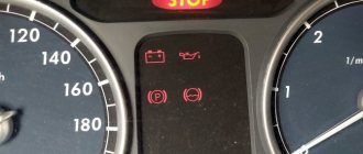
- A Check indicator appeared on the control panel. As practice shows, this lamp most often lights up when the controller breaks down, so to determine the malfunction you need to connect to the electronic control unit.
- Engine power has decreased. Of course, this symptom is indirect, since a decrease in power can be caused by various malfunctions, but, nevertheless, it cannot be ignored.
- Fuel consumption has increased. This problem can also be attributed to the failure of the fuel pump or fuel filter, but the performance of the mass air flow sensor also needs to be checked.
- In addition, the acceleration dynamics of the car will be reduced. As a result of less air entering the combustion chambers, the quality of the air-fuel mixture as a whole will be lower. Accordingly, because of this, the car cannot accelerate normally. And if you press the gas, then when accelerating the VAZ 2112 may move jerkily.
- Poor engine starting; in more severe cases, the engine will not start at all. This, again, is due to a poor-quality combustible mixture. Such a mixture can cause detonation, which contributes to poor engine starting. In addition, uncharacteristic popping noises may be heard from the exhaust pipe.
- When the car is idling, the engine speed will fluctuate. This problem is due to the different volume of air flow that enters the combustible mixture (the author of the video is the channel In Sandro’s Garage).
ADC codes
ADC code parameters relate to analog sensors of the control system:
Physically, ADC codes reflect the voltage that the sensor produces. Typically, these parameters are used to test sensor circuits. If fault codes occur associated with a low or high signal level of such a sensor, then the control system operates in backup modes. In this case, the value of the parameter related to this sensor is selected either from the emergency table or calculated using specified formulas, for example, the coolant temperature with a faulty temperature sensor increases during engine operation.
If, during a physical change in the parameter measured by the sensor, the ADC code remains a constant value, then the electrical circuit connecting the sensor is inoperative.
Flow meter failure: signs and causes of failure
Of course, the absence of a sensor or incorrect readings will not lead to a complete stop of the car. Moreover, the mass air flow sensor is checked, among other things, by the on-board computer. However, the symptoms will not allow you to move normally on the road:
- loss of engine power, up to the inability to drive uphill;
- engine jerking when moving evenly;
- hanging at high speeds after releasing the gas (this can be dangerous);
- increase in fuel consumption up to two times;
- engine vibrations reminiscent of “triple movement”, leading to increased wear of mechanisms.
With the exception of natural wear (any mechanism has a service life), other causes of malfunctions are associated with contamination of the MAF sensors or moisture and oil entering it. These problems arise due to an irresponsible attitude towards car maintenance.
- untimely replacement of the air filter;
- installation of low-quality or “zero” filters;
- water getting into the air duct channel (driving through puddles at high speed, careless car washing);
- penetration of oil vapors into the flow meter housing due to a malfunction of the crankcase ventilation system;
- debris and foreign objects that have entered the measuring channel after repair work or car maintenance.
Advice: do not rush to change a clogged flow meter; you can try to clean it with compressed air or a special aerosol for mass air flow sensors or carburetors.
Replacing the air flow sensor
To replace the sensor with your own hands, you need to prepare a shaped screwdriver and a “10” key.
The replacement procedure consists of the following steps:
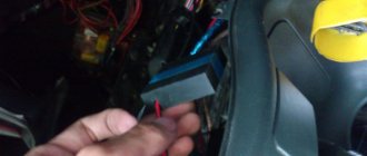
Disconnecting the sensor connector
Thus, if the car stalls and has all the signs of a breakdown of the mass air flow sensor, then before you start repairing it, you should check the level of its signal, it should not be low, perform a full diagnosis of the car and repair all faulty components and parts.
It is important to undergo regular vehicle inspections and perform timely maintenance, then the parts and components will last longer.
Methods for checking the camshaft sensor
Before testing the sensor using a multimeter or other electronic tools, you must check its mechanical integrity. In particular, it is installed in a housing with an O-ring, ensuring its secure fastening. We need to check its condition. It would also be useful to check the integrity of the sensor body, whether there are cracks or other damage on it. It is advisable to check the drive disk to see if the teeth are damaged or if there are metal shavings on the sensor body or nearby.
On the Internet you can find information that supposedly the DPRV can be determined to work by simply checking its magnetic properties. In particular, bring a small metal part to its end (the working sensitive part), which should “stick” to the sensor. In fact, this is not the case, and a non-working DPRV may or may not have magnetic properties. Accordingly, verification must be performed using other methods.
There are two main ways to test the camshaft position sensor - using an electronic multimeter and using an oscilloscope. The first method is simpler and faster, but the second is more accurate and provides more diagnostic information.
Checking the camshaft sensor with a multimeter
To check the DPRV, dismantling is necessary. This is not difficult to do; you just need to disconnect the contact group of wires from it and unscrew the fastening bolt. You will also need a small metal object (ferrous metal so that it is magnetic) to test.
Connection diagram for checking phase sensor 21110-3706040
Connection diagram for checking phase sensor 21120-3706040
The algorithm for checking the sensor with a multimeter is as follows:
- Take a multimeter and switch it to the DC voltage measurement mode in the range up to 20 V (depending on the specific multimeter model).
- Disconnect the “chip” from the sensor by unclipping the latch.
- Remove the sensor from its mounting location.
- On the “chip” of the sensor 21110-3706040 of a VAZ car (and on many others), contact “A” corresponds to ground, contact “C” is the positive wire, comes from the control relay, contact “B” is the signal wire (middle). For sensor chip 21120-3706040, contact “A” corresponds to ground, contact “B” is the positive wire from the control relay, contact “C” is the signal wire.
- Check the presence of power on the chips. To do this, you need to turn on the ignition on the car (but do not start the engine) and do this with a multimeter. If there is no power to the chips, then you need to look for the reason. This could be faulty wiring (insulation damage, broken wires), failure of the control relay, or a glitch in the electronic control system (ECU).
- Next, you need to connect the sensors for testing according to the diagrams shown in the figure.
- Apply a voltage of 13.5±0.5V to the sensor (although less is allowed, for example, 12...12.5 Volts from the battery).
- If, when power is applied to the sensor, the voltmeter detects a lack of voltage on the sensor, then this indicates either a breakdown of the sensor itself, the test can be completed and you can prepare to replace the sensor with a new one.
- Measure the voltage between the positive and signal contacts. It must be equal to at least 90% of the supply voltage (that is, if the supply voltage is 12 Volts, then the voltage at the signal contact must be at least 10.8 Volts).
- Bring a metal object prepared in advance to the end of the sensor (its signal part). Re-measure the voltage at the signal contact. It should be no more than 0.4 Volts. Remove the plate - the voltage value should be restored to 90.100% of the supply. If there are any deviations during the verification process, it means that the sensor has failed and must be replaced.
Checking the DPRV using an oscilloscope
An electronic oscilloscope helps to understand how the camshaft position sensor works and whether it produces pulses at all. Usually they use a so-called electronic oscilloscope, that is, simply a simulator program installed on a laptop or other similar device. You need to connect to the camshaft sensor and take an oscillogram from it. Ideally, there should be a smooth comb diagram with one drop-out peak that corresponds to the rapper passing through the sensor. If the oscillogram has a different shape, additional verification is needed.
When diagnosing the camshaft sensor of Nissan cars (in particular, Nissan Almera) with an oscilloscope, the shape of the oscillogram will be different. It will not be smooth, but in the form of 3 impulses, then a space, then 4 impulses - a space, 2 impulses - a space and one impulse - a space. For engines from this automaker, this feature is the norm.
Description of ADS1115 registers
The ADC has only 4 internal registers, all registers are 16-bit, respectively, for each write/read session, 2 information bytes are transmitted via the I2C interface (except for the register address byte). The registers are described in the table below:
| Address | Name | Register description |
| 0x00 | Conversion register | Conversion result storage register |
| 0x01 | Config register | Configuration register |
| 0x02 | Lo_thresh register | Setpoint register, minimum value |
| 0x03 | Hi_thresh register | Setpoint register, maximum value |
The configuration register is used to control the ADC; the register is described in the table below:
| Bit | Bit name | Bit value | Description |
| 15 | OS. The bit defines the state of the device and can only be written in low power mode | For recording | |
| No effect | |||
| 1 | Start conversion, for single conversion mode (low consumption) | ||
| For reading | |||
| Conversion in progress | |||
| 1 | Conversion complete | ||
| 14-12 | MUX. Multiplexer setup | 000 | AINp=AIN0 and AINn=AIN1 (default) |
| 001 | AINp=AIN0 and AINn=AIN3 | ||
| 010 | AINp=AIN1 and AINn=AIN3 | ||
| 011 | AINp=AIN2 and AINn=AIN3 | ||
| 100 | AINp=AIN0 and AINn=GND | ||
| 101 | AINp=AIN1 and AINn=GND | ||
| 110 | AINp=AIN2 and AINn=GND | ||
| 111 | AINp=AIN3 and AINn=GND | ||
| 11-9 | P.G.A. Amplifier Gain | 000 | FS=±6.144 V |
| 001 | FS=±4.096 V | ||
| 010 | FS=±2.048 V (default) | ||
| 011 | FS=±1.024 V | ||
| 100 | FS=±0.512 V | ||
| 101 | FS =±0.256 V | ||
| 110 | FS =±0.256 V | ||
| 111 | FS =±0.256 V | ||
| 8 | MODE. Operating mode | Continuous transformation | |
| 1 | Single conversion, low consumption mode (default) | ||
| 7-5 | D.R. Sampling frequency | 000 | 8 Hz |
| 001 | 16 Hz | ||
| 010 | 32 Hz | ||
| 011 | 64 Hz | ||
| 100 | 128 Hz (default) | ||
| 101 | 250 Hz | ||
| 110 | 475 Hz | ||
| 111 | 860 Hz | ||
| 4 | COMP_MODE. Comparator type | Comparator with hysteresis (default) | |
| 1 | Comparator without hysteresis | ||
| 3 | COMP_POL. Comparator polarity | Low active level (default) | |
| 1 | High active level | ||
| 2 | COMP_LAT. Comparator mode | Comparator without latch (default) | |
| 1 | Latch Comparator | ||
| 1-0 | COMP_QUE. Comparator control | 00 | Setting the output signal after one conversion |
| 01 | Setting the output signal after two conversions | ||
| 10 | Setting the output signal after four conversions | ||
| 11 | Comparator disabled (default) |
Basket
If Combiloader “does something wrong” or does not do what you think it should do, or does it incorrectly, you need to contact technical support at
This is easy to do if you back up “I can’t”, “it doesn’t work” or “doesn’t want” with a diagnostic log.
How to get it? Just!
1) Download the PortMon program 2) Launch PortMon. It may matter which folder it is launched from. You must NOT receive the message “Unable to load driver.” at startup. 3) Edit-Max output bytes set to 1024 -> Apply. 4) Edit-History depth -> 0 -> Apply 5) Computer -> Disconnect 6) Computer -> Connect local 7) Options -> ShowTime and ShowHex only. Capture -> Capture Events checkbox. 9) Capture -> Ports -> Check the box next to the host/Loader port. 10) Minimize (not close) PortMon. 11) Run the diagnostic program/Bootloader. 12) Reproduce the steps that lead to the error. 13) Close the diagnostic program/Bootloader. 14) Return to PortMon. 15) File -> Save As -> enter the file name and send it to me zipped.
(Points 3 - 9 must be done once, they will be remembered, point 9 may have to be monitored)
If differences with other programs were noticed, do the same with them.
ATTENTION! After starting PortMon, there is no need to remove the host. If you remove it, it will be able to “appear” in the system only after a reboot.
Terms of refund for goods sold
In accordance with the current legislation of the Russian Federation (Law on the Protection of Consumer Rights), the buyer has the right to refuse the ordered goods at any time BEFORE receiving the goods.
The acquisition of the right to use a computer program (license) on the basis of a license agreement is regulated by the norms of the Civil Code of the Russian Federation. Unilateral refusal of the acquired right of use (at the user’s initiative) is not provided for by law, and therefore previously purchased licenses are not subject to return and no refunds are made for them.
Refunds are made only if the electronic key for the computer program copy has not been activated and there is confirmation from the copyright holder.
Let's compare architectures
At the moment, there are many different ADC architectures in the world. Each of them has its own advantages and disadvantages. There is no architecture that would achieve the maximum values of all the parameters described above. Let's analyze what maximum speed and resolution parameters the companies producing ADCs were able to achieve. We will also evaluate the advantages and disadvantages of each architecture (you can read more about the various architectures in the article on Habr). Architecture comparison table
| Architecture type | Advantages | Flaws | Maximum resolution | Maximum sampling rate |
| flash | Fast converter. The conversion is carried out in one clock cycle. | High power consumption. Limited resolution. Requires a large crystal area (comparators). It is difficult to coordinate a large number of elements (as a result, low yield). | 14 bit 128 kSa/s AD679 | 3 bit 26 GS/s HMCAD5831 |
| folding-interpolated | Fast converter. The conversion is carried out in one clock cycle. Requires fewer comparators due to preliminary “convolution” of the entire processing range into a narrower range. Occupies less space. | Errors associated with the nonlinearity of the convolution block. Delay for establishing levels in the convolution block, which reduces the maximum fs. Medium resolution. | 12 bit 6.4 GS/s ADC12DL3200 | 12 bit 6.4 GS/s ADC12DL3200 |
| SAR | High accuracy. Low power consumption. Easy to use. | Limited speed. | 32 bit 1 MSa/s LTC2500 | 10 bit 40 MSa/s XRD64L43 |
| pipeline | Fast converter. Highest accuracy among fast ADCs. Doesn't take up a large area. Has lower consumption among similar fast converters. | Pipeline delay. | 24 bit 192 kSa/s AK5386 | 12 bit 10.25 GS/s AD9213 |
| dual-slope | Average conversion accuracy. Simplicity of design. Low consumption. Resistance to changes in environmental factors. | Processes low frequency Signals (low fs). Mediocre resolution. | 12+sign bit 10 S/s TC7109 | 5+sign bits 200 kSa/s HI3-7159 |
| ∑-Δ | The highest conversion accuracy thanks to the “Noise shaping” effect (specific filtering of quantization noise) and oversampling. | Cannot work with wideband signal. | 32 bits 769 kSa/s AK5554 | 12 bit 200MS/s ADRV9009 |
Term: ADC
Analog-to-digital converter (ADC) is a device that converts an input analog signal into a digital signal (digital binary code). For tasks of measuring the value of a signal at an arbitrary point in time, an asynchronous mode of operation with an ADC with single analog-to-digital conversions that are not strictly time-bound is used. For tasks of measuring the functional dependence of changes in an analog signal, the synchronous operating mode of the ADC is used. The synchronous mode of operation of the ADC without missing data over an arbitrarily large time interval is also called streaming mode. Synchronous ADCs, as a rule, support the frame-by-frame principle of data acquisition, when digitized measurement reports form conditional frames with a specified number of samples corresponding to specified measurement channels.
The ADC is an integral part of the data acquisition system.
Main parameters of the ADC:
Types of mass air flow sensors, their design features and operating principle
Three types of VU meters are most widespread:
- Wire or thread.
- Film.
- Volumetric.
In the first two, the operating principle is based on obtaining information about the mass of the air flow by measuring its temperature. The latter may involve two accounting options:
- By changing the position of the slider, driven by a special blade, which is affected by the air flow passing through the device.
Considering the presence of rubbing mechanisms, the level of reliability of such structures is quite low. This was the main reason for the refusal of car manufacturers from sensors of this type. For reference, here is a simplified example of the design of a volumetric flow meter. Volumetric air flow sensor device - By counting Karman vortices. They are formed if a laminar air flow washes over an obstacle whose edges are quite sharp. The frequency of the vortices breaking off from them is directly related to the speed of air flow passing through the device.
Vortex sensor design (widely used by Mitsubishi Motors)
Legend:
- A – pressure measurement sensor to record the passage of the vortex. That is, the frequency of pressure and vortex formation will be the same, which makes it possible to measure the flow of the air mixture. At the output, using an ADC, the analog signal is converted to digital and transmitted to the ECU.
- B - special tubes that form an air flow similar in properties to laminar.
- C – bypass air ducts.
- D – column with sharp edges on which Karman vortices are formed.
- E – holes used to measure pressure.
- F – direction of air flow.