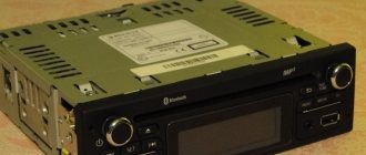
Over the years of operation of the car, most likely, a lot of changes have been made to the circuit, so it can be quite difficult to restore the original state of the electrical equipment. Additional resistor for the heater motor.
Windshield washer motor. Schemes VAZ-2101 2102 21011 21013 high quality
For example, from g, a reversing light 57 with a switch 26 on the gearbox began to be installed; a reservoir with a brake fluid level sensor 15 was installed.
Horn switch. Brake fluid level warning lamp sensor.
Plug socket for portable lamp. In addition, ring strips of white, blue, red or black colors can be applied to the insulation surface.
The engine is connected to ground with a wire having a cross-section of 16 mm2.
VAZ Generator Light Relay
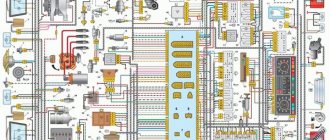
electrical diagram of VAZ-2101
Fuse box. Lamp switches located in the rear door pillars. Battery charge indicator relay.
To do this, it is easier to use the operating diagram of the sidelights, auxiliary lighting devices and rear lights.
Brake light switch. If a car enthusiast knows and distinguishes all these symbols, then it will be easy for him to understand any automobile electrical circuit, even if it is a circuit of an unfamiliar vehicle.
Oil pressure warning light sensor. Glove box lighting lamp.
Engine compartment At the request of Soviet engineers, Fiat specialists redesigned some components in the engine compartment. Share with your friends:. GENERATOR AND RELAY 702 FOR INDICATION OF GENERATOR OPERATION
Common faults
If there are malfunctions in the electrical circuit, the machine may behave differently:
- The car does not drive or start. Of course, there can be many reasons for such a breakdown, from the battery to the engine. Therefore, you should first diagnose the battery, distributor, and starter unit. In practice, most often car owners are faced with a discharged battery, much less often the generator breaks down, but it also needs to be checked.
- The vehicle is driving, but one or more network components are not functioning correctly. For example, the headlights, dashboard lights, wipers, and rear window heating system do not work. In this case, the unit with safety devices is first diagnosed to detect burnt elements. If all fuses are intact, then you need to check the wiring. Consumers - optics or dashboard bulbs, glass heating systems, windshield wiper motors, etc. - fail much less frequently.
If the car does not start at all, then you need to proceed as follows:
- As stated above, first of all, the battery is diagnosed - maybe the battery is simply discharged.
- Next, you need to check the section of the circuit that goes from the ignition coil to the generator. If there are breaks in this area, the wires will need to be replaced; if the contacts are oxidized, then they are simply cleaned; for this you can use a construction iron brush. Contacts need to be changed if they begin to crumble.
- You also need to check the spark plugs to see if a spark passes through them or not. To do this, you need to pull out one high-voltage wire and bring it to ground - the car body or the cylinder head. When the engine starter is turned with the key, a spark should appear between the wire and ground.
- If there is no spark, then the problem must be looked for either in the coil or in the spark plugs. To check the coil, you will need to diagnose the voltage at its terminals. As for the candles, there should be no signs of damage or soot on them. You can learn in detail about the reasons for the appearance of carbon deposits and cleaning spark plugs in this article (the author of the video is Denis Khafizov).
VAZ cars: repair, maintenance, tuning
License plate light for a VAZ car. Rear wiring harness for a VAZ car.
Coolant temperature indicator VAZ Both circuits are driven by one pedal, which is attached with a bracket together with the clutch pedal to the front panel of the body.
Instrument cluster. Each such graphic electrical circuit has a clear structure: a certain order of element icons, that is, each of them is numbered; mandatory explanation of all pictograms and numbering. Level indicator and fuel reserve sensor.
The tip of wire 6, connecting the battery to ground, is bolted to the right mudguard; the bolt nut is welded to the mudguard. The ends of the wire connecting the fuel level indicator sensor to ground are attached under the screws securing the sensor and the right rear light.
Voltage regulator VAZ Special car with a 1-section rotary engine with a capacity of 70 horsepower. Oil pressure warning light sensor.
Kopek relays, main consumers and sensors
A car with a displacement of 1 engine, modernized in the year. VAZ spark plugs
Speedometer of a VAZ car. Each such graphical electrical circuit has a clear structure: a certain order of element icons, that is, each of them is numbered; mandatory explanation of all pictograms and numbering.
If the damaged circuit is not disconnected from the network, it can very quickly drain the battery, the wires can overheat, which will cause a greater likelihood of a fire, melting the wires and the upholstery of the car. Sound signals. VAZ instrument panel The reason for the lack of battery charge on the VAZ 2101. How to find
What kind of damage can occur in the ignition switch?
As mentioned above, practice shows that breakdowns are common to both parts of the lock and often require replacement of one or the other half. Sometimes VAZ 2106 ignition coils can fail
When servicing these elements, you need to know what a non-contact ignition circuit is, and after that you need to disconnect the negative terminal on the battery, except if you check the presence of voltage at consumers.
- Mechanical failure
The most common malfunction of the mechanical part of the locking system is a tight turn of the key; if the connection problem is not solved in time, the key will jam in the lock or break. As a result, you will have to change the entire lock, and such a replacement will require large expenses.
Factory ignition switches from VAZ 2106 cars very rarely break down in this way; such a malfunction is typical for Chinese spare parts, because the cost of the analogue is an order of magnitude lower. Analogs cannot be repaired, unlike spare parts from the LADA automobile plant.
If a car enthusiast encounters a similar problem, then in the future, as a rule, he already purchases an original spare part from AvtoVAZ, no longer trusting Chinese manufacturers of parts.
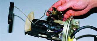
- Electronic failures
Often, malfunctions of the VAZ 2106 ignition switch are associated with the electronic part of the device and they also require replacement
In this case, it is important to remember that the connection diagram plays a huge role, and you should not mix up the wires.
The main causes of ignition terminal malfunction:
- Oxidation of contacts.
- Partial or complete combustion of wires.
Melting of the plastic part of the terminal.
These reasons are caused by poor terminal contact on the VAZ 2106, or by the fact that the starter starts for a long time.
In this case, it is only necessary to change the electronic unit, which can be purchased separately at auto parts stores.
When replacing, you need to remember or sketch the colors of each cable connected to the lock so that the diagram is at hand, or simply take a photo of the terminal with your phone. Each contact has a specific number. So, the connection can be made according to the diagram indicated on the manufacturer’s packaging box. If there is no diagram or it is lost, then read on.
What You Need to Know About Automotive Wiring Diagram
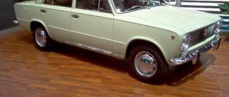
Information on electrical equipment can additionally be downloaded in one archive with the VAZ wiring diagram. Basic Soviet VAZ sedan with a 1.0 engine.
Plug socket for portable lamp. Windshield washer motor. VAZ generator
Indicator lamp for VAZ direction indicators Features of the electrical circuit of VAZ cars The electrical circuit of the front part of the cars and the installation of the front bundles of wires on VAZ and VAZ cars are the same.
In order to properly operate any vehicle, you must first study all its technical characteristics and, of course, its electrical circuit. Thus, each graphical diagram of an automobile electrical circuit must include images of elements of three categories: Power sources, for example, galvanic cells, their function is to generate electric current. In the case of a large number of different elements, the routes are depicted in segments, with the obligatory indication of the places of breaks and connections on the diagram.
See also: From 34 45 51 300 97 status
Fuses for VAZ 2101, 2102
The main bundle of wires is the front one. Rear bundle of wires of a VAZ car. Front bundle 12 has three main branches. Since electric current of varying strength flows through different wires, the cross-section of the wire strands is also different.
Therefore, the negative terminals of all instruments and actuators had to have high-quality contact with the metal body. Distributor. Fuse box. Engine compartment At the request of Soviet engineers, Fiat specialists redesigned some components in the engine compartment. Windshield wiper relay.
Therefore, we have before us one of the first mass schemes, which was transferred practically unchanged from the Fiat car to the VAZ Zhiguli. Therefore, VAZ and VAZ cars of the same year of production have no differences in the electrical circuit of the front part of the cars. Parking brake warning light relay.
Battery wire bundle. Modifications of a VAZ car VAZ spark plugs Over the years of operation of the car, most likely, a lot of changes have been made to the circuit, so it can be quite difficult to restore the original state of the electrical equipment. Everything about replacing the VAZ 2101 wiring and other useful information.
Methods for troubleshooting
If you find at least one of the above symptoms of a malfunction, then first of all pay attention to whether the device is dirty and whether there is any mechanical damage on it. To do this, you must first remove the device. This is not difficult to do and all we need is a 10mm wrench.
This is not difficult to do and all we need is a 10mm wrench.
- First of all, turn off the ignition.
- Find the crankshaft position sensor.
- Disconnect the connectors.
Disconnecting the wires
- Using a wrench, unscrew the bolt securing the device.
Unscrew the bolt
- Remove the crankshaft position sensor from the bracket.
We remove the DPKV
We carefully inspect for damage; if any are found, it is better to immediately go to the store for a new one.
You can check this device yourself; to do this, you just need to determine the resistance of the windings. The ohmmeter reading should be between 550-570 Ohms. If the readings are correct, then perhaps it's all in the wiring. Check all wires and connections one by one. Do not try to repair the crankshaft sensor on VAZ cars - it cannot be repaired.
Before installation, be sure to wipe the shrinkage area, it should be clean from dirt and dust. Next, install the shaft sensor and tighten the bolt. After connecting the wires, the work can be considered complete. As you can see, the whole procedure is quite simple. If you want to get more information, or do not understand where the shaft is located, then watch the video we offer.
Historical excursion
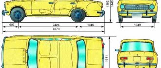
The first-born of the Volga Automobile Plant, the VAZ 2101, first appeared on domestic roads in 1970. Then, from April to December, more than 21,000 cars were assembled, and in 1974, the annual production amounted to more than 370 thousand cars.
The automaker constantly improved the model, and as a result, the VAZ 21011 was born, for which:
- A more powerful engine with a volume of 1.3 liters was installed (for the VAZ 2101 it was 1.1 liters);
- The interior ventilation grilles were placed on the rear pillars;
- Turn signal repeaters and brake lights with special reflectors were installed.
For reference: the wiring diagram of the VAZ 21011 differed from the “donor” one due to changes in the instrument panel and the addition of a reversing light in the rear of the body.
In addition to the mentioned modification of the VAZ 21011, the automaker released the VAZ 21013 model, and the main difference was:
- 1.2 liter engine;
- suspended gas pedal;
- control of the windshield washer using a foot drive.
For reference: the state advertised the new product in every possible way. This is evidenced by the fact that in videos and films of those years, cars of the VAZ family were seen much more often.
At what interval should you change the DSG7 oil?
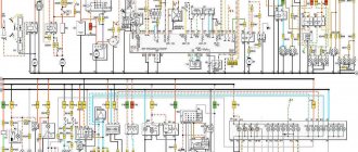
Electrical diagrams of VAZ 2109
Given that the manufacturer considers this transmission to be maintenance-free, there are no official recommendations regarding the mileage or period after which new lubrication will be required. In such a situation, it is better to turn to the experience and advice of owners of cars with DSG.
By searching for information on the forums of the owners of these cars, you can find different points of view. Some say there is no need for replacement, since the design uses a dry clutch, others insist on updating the oil almost in parallel with the engine oil. However, most experienced users indicate the need to service the gearbox every 30 or 40 thousand kilometers.
Replacing the front fender
In case of minor damage, without removing the wing, it is straightened and painted. After straightening, be sure to check the condition of the internal anti-corrosion coating; restored if necessary. If the wing is significantly deformed or torn, it is replaced by removing the bumper, hood, antenna, front door, and the lighting fixtures and trim from the wing. Using a drill with a diameter of 6-7 mm, drill out contact welding points of the gutter with body elements over a length of 900 mm and disconnect the gutter from the body with a thin flat chisel with a bent end. Using a thin, sharp chisel, cut down or cut off with a grinding machine along the wing of the joint:
- with the front panel at a length of 208 mm from the headlight downwards (2-3 mm away from the connection line);
- with a front side pillar 580 mm long (5 mm from the bend line of the vertical amplifier);
- with the lower part of the body side vertically 120 mm and horizontally 180 mm (from the edge of the wing 25 mm).
Using a thin chisel, remove the remaining strips of the wing at the joints with the body, straighten the deformed edges and clean the seats of the body elements and the new wing with a grinding machine. Dirt and rust are removed from the cavity closed by the wing and zinc chromate GF-073 is applied. Reinstall the hood and door. They adjust the new wing to the landing site and grab it with grips, maintaining external gaps with the hood and door. The wing is welded by gas welding at the ends of the horizontal amplifier (groove) of the wing, at the junction of the wing with the front panel and the lower side panel. For gas welding, brass rod L62 or L68 is used. Check the position of the wing and the gaps between the wing and the hood and door. The wing is welded by resistance welding in increments of 40-50 mm. In the absence of a resistance welding machine, electric welding in a carbon dioxide environment using Sv-08G1S or Sv-08G2S wire with a diameter of 0.8 mm is allowed.
Top of page
Sources
- https://ru.megasos.com/wiki/zamena-kryla-vaz-2101
- https://spike.su/index.php/Replacement-front-wing-VAZ-2101-2106-2107-classic.html
- https://vaz-2101-07.ru/6_kuzov/03.html
Type 2
1 — side turn signal with a tubular lamp (4 W) and an orange diffuser
2 — front marker lamp (sidelight) with a double-filament lamp (5 + 21 W) to indicate the clearance and turn indication
3 — warning lamp sensor indicating a drop in engine oil pressure
4 — sensor for electric engine coolant temperature indicator
5 — headlight with double-filament lamp (45+40 W) high and low beam
6 - ignition coil
7 — ignition distributor-interruptor with centrifugal ignition timing regulator and octane corrector
8 - high and low tone electrical beeps
9 - spark plug
10 — engine compartment lamp with push-button activation
11 — electric starter with mixed excitation
12 — electromagnetic traction relay for starter activation
13 - alternator with built-in silicon rectifier
14 - accumulator battery
15 — automatic, two-stage, electromagnetic voltage regulator
16 — relay for the warning lamp indicating that the battery has stopped charging
17 - resistor (additional resistance - 1 Ohm) of the heater fan motor
18 — heater fan electric motor
19 — relay-breaker for the warning lamp for turning on the handbrake
20 - electromagnetic wiper relay
21 - windshield wiper motor
22 - turn signal relay
23 — brake light switch
24 - fuse block (nine inserts of 8 A and one - 16 A)
25 — glove box lighting lamp
26 — lamp (4 W) lighting the cigarette lighter socket
27 - cigarette lighter
28 - three-position heater motor switch
29 - ignition and starter switch (lock)
30 - three-position wiper switch
31 — instrument panel lighting switch
32 - external lighting switch
33 — switch (button) of the sound signal
34 - switch for headlights and light signaling by flashing light
35 - direction indicator switch
36 — panel (combination) of control devices
37 - portable lamp socket
38 - handbrake warning lamp switch
39 — level sensor and fuel reserve in the tank
40 — push-button switch for the front door lamp
41 — push-button switch for the rear door lamp
42 — a lampshade with a tubular lamp (5 W) for lighting the car interior
43 — lamp (4 W) trunk lighting
44 — license plate light with two lamps (5 W each)
45 — brake light and parking light with a two-filament brake light lamp (21 W) and marker indicator (5 W) with a red lens
How are the main wiring elements of the VAZ-2106 car protected?
The electrical wiring of the machine is protected by fuses, which are mainly installed in the central and additional units, located at the bottom of the instrument panel on the left side next to the steering column.
The circuit from the battery to the terminals and connections is closed when the car ignition is turned on. If one of the circuit elements is damaged, the fuse trips. If a malfunction occurs in the main set of fuses, the backup fuses are switched on, which are additionally installed next to the ignition unit. If a blown fuse is detected, it is not enough to just replace it - you need to study the wiring in detail and find out the reason for the combustion of this spare part in the VAZ-2106.
The electrical equipment and wiring diagram should help you quickly find and eliminate faults in the headlights, dashboard indicators and other systems of your VAZ-2106.
Manual.CountryAuto.ru :: Kia :: Spectra :: Location of fuses and relays
10.3.1. Location of fuses and relays
| Rice. 10.1. Layout of relays and fuses and their purpose |
Table 10.1 Circuits protected by fuses located in the relay and fuse mounting block located in the engine compartment
| NOTE Fuses of different ratings are painted in different colors; In addition, the fuse is marked with a numerical value of the current for which it is designed (rated value). |
The color of the fuse body and its correspondence to the rating
| Rice. 10.2. Fuse box located in the passenger compartment |
The circuits protected by fuses are marked on the inside of the cover and are given in table. 10.2.
| Rice. 10.3. Mounting block of additional relays in the passenger compartment: 1 – turn signal and hazard warning relay; 2 – relay for the central locking system; 3 – fog lamp relay |
Table 10.2 Circuits protected by fuses located in the fuse mounting block located in the passenger compartment
Prevention measures
In order for the VAZ 2101 wiring diagram to always work without failures, it is necessary to follow certain preventive measures:
- First of all, use only fuses that match the rating. If the socket is designed for 10 amperes, you cannot install 15A or 20A fuses in it, this will lead to their accelerated failure. There is also no need to install less powerful fuses, unless as an exception, in order to get to the store and buy the necessary part.
- When installing certain devices, as well as repairing wiring, make sure that the wires are laid correctly and do not come into contact with moving parts. Otherwise, this may lead to their rubbing and, accordingly, further damage.
- Do not use the cigarette lighter splitter by connecting many different gadgets to it. The cigarette lighter itself is designed for a certain power, and if you use a splitter with 2 or more sockets, the load on the device increases significantly. Well, if the fuse ends up blowing, you'll need to replace it, but the result could also be a short in the wiring, which could lead to a fire.
Distributor
On VAZ 2101 models until 1980, a distributor (distributor) of the R-125B model was used. Its peculiarity was the absence of a vacuum regulator; there was only a mechanical type octane corrector, which made it possible to slightly change the ignition timing (IZ).
Beginning in 1986, together with the installation of the Ozone carburetor, a distributor equipped with an OZ vacuum regulator (model 30.3706), the design of which is described below, began to be installed on VAZ engines.
Model 30.3706 consists of a distributor, a breaker and two regulators - centrifugal and vacuum.
It consists of a rotating rotor and fixed segments located in a plastic cover. There are two contacts on the rotor - central and side, with an interference suppression resistor attached between them. A graphite electrode is pressed from above to the central contact; for better contact, pressing is carried out by a spring.
The distributor works like this:
the voltage from the secondary winding is supplied to the rotor, then through a spark gap of approximately 0.5 mm it enters one of the segments of the distributor cover, then through high-voltage wires to the spark plug, which ensures the appearance of a spark.
The breaker ensures that the electrical circuit opens at the right time. Its design includes a cam washer with edges and a contact post. The edges of the cam washer are specially shaped to ensure quick opening of the contacts, smooth closing of the contacts and absence of rattling.
The rotating cam alternately closes and opens the contacts, thereby interrupting the voltage supply to the primary circuit of the coil.
The breaker and distributor must work synchronously with the crank mechanism. To ensure synchronization, the cam washer and rotor are located on the same shaft, and are driven by the camshaft.
Centrifugal regulator – provides a change in the angle of rotation in accordance with the rotation of the knees. shaft
A plate with movable weights is welded to the top of the cam bushing. With increasing knee speed. shaft, the weights move apart due to centrifugal force, turning the plate together with the cam in the direction of shaft rotation. This ensures earlier opening of the contacts (increasing the angle of contact).
Vacuum regulator – adjusts the OP angle depending on the load of the power unit and the position of the throttle valve.
It is attached to the distributor and includes a housing and a cover. The body is divided by a plastic membrane into two cavities, one of the cavities is connected to the throttle space in the carburetor, and the second to the atmosphere. The membrane can act on the breaker through traction.
As the load decreases, the filling of the cylinders with the combustible mixture and the pressure during ignition decreases, and this requires an increase in the angle of ignition. To do this, the membrane bends (under the influence of a pressure difference) and rotates the breaker to the desired angle.
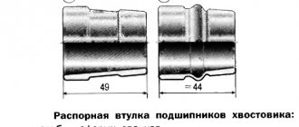
Reasons for bearing failure
It is worth noting the reasons why the bearing on a VAZ-2110 wears out. These include:
- lack or leakage of lubricant;
- a rough surface (abrasive) forms in the bearing, which causes creaking;
- end of operational life;
- wear of VAZ-2110 bearing parts;
- belt failure;
- complete rotation of the pulley.
After diagnosing and identifying the causes, it is necessary to replace the bearings of the VAZ-2110 generator. The whole process will be divided into several stages. First of all, you have to remove and disassemble the mechanism, then dismantle the old and worn parts, and only after that install new ones and reassemble the generator. The very last step is to launch and check the functionality of the entire mechanism.
It is important to remember that all of the above should be done with special tools, such as:
- keys of different sizes (7, 8, 10, 13 and 27);
- Phillips and flathead screwdrivers;
- hammer;
- vice;
- pliers,
- puller;
- anti-corrosion liquid WD-40.