Depending on the engine design, gas leakage from one engine cylinder into the crankcase space ranges from 10 to 30 l/min. In the operating area of the oil scraper rings, due to the high speeds of piston movement, crankcase gases are enriched with oil particles ranging in size from 0.1 to 2 microns. In addition, the formation of an oil aerosol is facilitated by constant mixing of the oil in the oil bath by a rotating crankshaft.
Crankcase gases contain motor oil, which is suspended in the form of oil mist. Filter modules as part of the lubrication system of modern engines have a special system for separating engine oil from crankcase gases (oil separators).
Existing crankcase ventilation systems allow two options for removing crankcase gases:
- removal of crankcase gases to the atmosphere
- return of crankcase gases to the engine intake manifold
The first method of crankcase ventilation is practiced by few automobile engine manufacturers, and today it does not meet environmental requirements.
The second method reduces the emission of crankcase gases into the environment, but, on the other hand, due to the oil particles contained in the crankcase gases, other problems arise:
- the appearance of deposits on hot engine components, for example on turbocharger blades, which leads to reduced service life
- varnish deposits in the elements of the intake air cooling system
- oiling of the intake tract
- increase in particulate matter in exhaust gases
Therefore, crankcase ventilation systems of a modern internal combustion engine must ensure the separation of oil particles. This is caused by tightening environmental protection requirements, namely reducing the content of particulate matter in exhaust gases.
To separate oil particles from crankcase gases, oil separators of various designs are used. Initially, synthetic fiber was used as an oil separator, which was installed in the form of a filter fabric in the oil separator housing and retained oil particles carried away by the flow of crankcase gases in the engine crankcase ventilation system.
Rice. Oil separator with synthetic separator: 1 – synthetic filter element; 2 – crankcase gases purified from oil; 3 – crankcase gases containing oil particles; 4 – separated oil
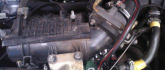
The engine oil thus retained was collected at the bottom of the oil separator housing and, through an opening, returned back to the engine oil bath. Structurally, the oil separator is integrated together with the oil filter into the so-called filter block (module).
Rice. Appearance of the filter unit: 1 – oil filter; 2 – oil separator
However, during operation, the properties of the synthetic fiber filter cloth gradually deteriorated, as it became contaminated with resinous substances formed as a result of the inevitable aging of the oil and its oxidation, as well as solid particles, mainly carbon in the form of soot, especially in diesel engines. Contamination of the filter fabric led to an increase in the resistance to the passage of crankcase gases through it, which, in turn, led to a deterioration in the performance of the crankcase ventilation system and dictated the need to replace the oil separator filter element.
Purpose of the crankcase ventilation system (CVG)
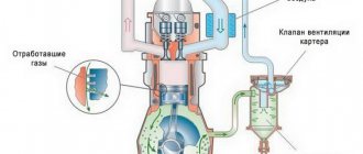
Crankcase ventilation is necessary to continuously remove the toxic mixture of unburned hydrocarbons, exhaust gases and oil mist. Before the tightening of environmental standards, the breather, a piece of hose connecting the engine block and the atmosphere, did an excellent job of this task.
In modern realities, crankcase ventilation is a closed system. Exhaust gases are fed into the intake manifold, where they are mixed with a fresh charge and safely burned in the engine.
Replacing KVKG
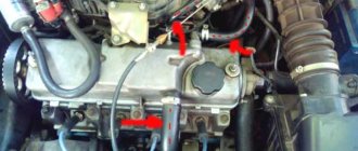
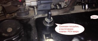
Replacing a valve is easy on almost any passenger car, but each SVKG engine model has its own design features. Let us consider, as an example, how the KVKG changes on the M54 B22 engine, the make of the car is a BMW fifth series in the back of an E39. The KVKG valve is located under the intake manifold at the front of the internal combustion engine, and to get to it you need to remove:
For convenience, you can remove the intake manifold itself, but then the work turns out to be quite labor-intensive, and you will also have to purchase manifold gaskets. After access to the valve is ensured, disconnect the hoses from the KVKG and dismantle the device itself. We are installing a new mechanism, putting all the parts in their places.
Operating principle of the oil trap
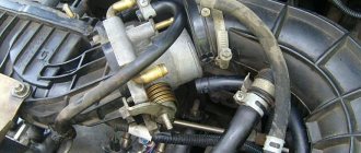
An oil separator is a device that is capable of separating and trapping oil particles in a gas or liquid stream. In a car, it is installed directly in the internal combustion engine to prevent engine oil from entering the intake manifold.
The device is an elongated flask, which is divided into 2 parts by a cone. It is along the walls of the cone that oil particles flow down. This occurs due to centrifugal force, which, from the flow of air mixture entering the apparatus through its upper part, carries oil particles into a separate cavity for collection through the lower part of the inertial cyclone filter.
Thread separation
The standard crankcase ventilation system has two pipes for supplying gases to the intake tract. This is due to the difference in pressure in front of the throttle and in the space behind the throttle. In minimum load mode, when the throttle valve is barely open, the flow area is minimal, so the greatest vacuum is in the throttle space. In heavy and full load modes, an open throttle valve does not create significant resistance to the flow of air, so the vacuum in the intake tract is minimal. Separation of entry points allows flexible dosing of crankcase gases.
PCV valve
The crankcase ventilation system valve is necessary to limit the vacuum. High vacuum, as well as excess pressure, can damage the seals. Therefore, the PCV valve allows crankcase gases to enter as the vacuum in the intake manifold drops.
In normal condition, the valve is held open by a return spring. When the engine is idling, the vacuum overcomes the spring force and closes the channel connecting the engine crankcase and the intake manifold. Accordingly, as the throttle valve opens and the vacuum decreases, the return spring slightly opens the channel for gas access.
On many VAG vehicles with a two-stage filtration system, the PCV valve's job is to interrupt the flow from the coarse stage to the fine stage.
A wise decision
The increased pressure that is constantly applied to the oil worsens the properties of the lubricant over time. Without a crankcase gas oil separator on the Polo, for example, the lubricant itself ages faster and its service life is significantly reduced, which entails frequent replacement of consumables. To avoid unnecessary pressure in the engine crankcase, a special exhaust gas ventilation system is provided. However, the standard separator, which is installed by many manufacturers on cars, does not completely clean the crankcase gases from oil particles. Therefore, some car enthusiasts install an additional device.
Most drivers of domestic and foreign cars with impressive mileage have often encountered sticky oil deposits on various parts of the engine. Often this is:
- intake tract;
- throttle valve;
- intake manifold;
- idle control valve;
- air filter - oil can get here through the mass air flow sensor (MAF).
By interacting with the mass air flow sensor, the oil can cause its failure, and replacing it costs 2500-3000 rubles. Isn't this a reason to take care of an additional measure in the form of a crankcase oil separator on a Citroen-Picasso or any other car?
Why is the PCV valve important?
Faulty PCVs can cause engine oil contamination, sludge buildup, oil leaks, high fuel consumption, and other engine damage problems, depending on the type of fault.
While some of these problems can be caught before they escalate with simple checks, failure of the PCV valve or related components often results in costly repairs. This is because most car owners do not include the PCV system in their maintenance routines. Even though some car manufacturers suggest replacing this part regularly, car owners still forget to replace it. Additionally, not all manufacturers emphasize the importance of regular system checks.
Symptoms of a Stuck PCV
- Engine misfires at idle
- Lean air-fuel mixture
- Presence of engine oil in PCV valve or hose
- Increased oil consumption
- Hard engine start
- Rough, unstable engine operation at idle
Additionally, a stuck PCV valve can cause a check engine light due to increased air flow. And the diagnostic computer may mistakenly show this error due to the mass air flow sensor or oxygen sensor, making it difficult for you to identify the real source of the problem.
Serious damage to the engine
Burnt gases have a negative impact on the oil and reduce engine efficiency. In fact, crankcase gases are unburnt fuel residues and contain many harmful impurities that have a detrimental effect on the environment. The presence of water evaporation in gases leads to the formation of an emulsion, due to which foam is observed in the oil. Because of it, the rubbing elements do not receive a sufficient amount of lubrication, due to which they wear out faster and fail. And the vapors themselves that fall on the oil dilute it. Various impurities are formed, which have the most destructive effect, reducing the durability of almost all parts with which the oil comes into contact. As a result, the engine life is reduced several times.
Device installation
The crankcase gas oil separator is installed depending on the engine type:
- carburetor;
- injector.
In carburetor engines, the device is mounted directly in front of the air filter, which regulates crankcase gases. If it is an injector, the device is connected to the inlet pipe located close to the throttle valve and cylinder block cover.
The system is now ready for use. However, for its high-quality and productive functioning, installation alone is not enough; it is necessary to inspect the device from time to time and carry out regular maintenance. To do this, the device must be disconnected from the system and rinsed thoroughly, completely getting rid of any remaining accumulated oil. In this case, treatment with a solvent will not interfere.
After the maintenance procedure, the crankcase gas oil separator device is put into place and can be used for further operation. There is no need for frequent inspection and maintenance; the frequency can be at least once every two months.
As is already known, oil leakage not only has a negative impact on the efficiency of the engine, but also significantly reduces its service life. A homemade device allows you to eliminate this problem to some extent. However, the lubricant itself also plays a key role. Therefore, you should not save on purchases; it is better to purchase only high-quality products. No engine will put up with cheap oils whose quality is questionable.
What problems may arise
- Gases mix with oil. It changes its physical properties. This will negatively affect the life of the motor;
- Excessive pressure is created inside the engine. This leads to “squeezing out” of gaskets and seals. Where there are weak spots in the seals, there will be oil leaks and oil fogging.
Often on older cars you can notice leaks through the crankshaft oil seal and valve cover gasket. In worst cases, pressure raises the dipstick.
Therefore, we must remove these gases from the crankcase. If your stomach is bloated, you feel like you're going to burst. So is the motor. He needs to “fart his way through”, excuse the expression. If it doesn’t do this, then you will spend money on repairs and constantly adding oil.
Recommendations
Comments 45
Good evening. I also have a problem with gases from the filler neck. Volz CC 2L turbo. The gases are leaking from the filler neck. Does anyone know how the injectors are installed there? Maybe because of the rings under them, gas is going into the crankcase or some other reason. Has anyone encountered this?
is there an injector pump?
Thanks everyone, got it :-)))
That’s how we learn...bit by bit!))
Once again I’ll send a link to my words... regarding gas breakthroughs through the injector washer www.starexclub.ru/forum/d...%20through%20injector.JPG
good old starex club)
...a treasure trove...like MIKROB)))))
Is it burning oil? How's the compression? If the engine is running normally - it doesn’t consume oil, the antifreeze doesn’t disappear - consider that this is how it should be)
I'm okay, this is me for general education)
Then don't worry)
I'm okay, this is me for general education)
you also need to look at the oil intake mesh in the pan)))) when the engine breathes, the oil often burns and suspensions clog the mesh... then it leaks oil
For example, my injectors are inserted through the oil seal into the valve cover, and the main part of the injector body ends up in the cavity between the cover and the head body. With this method, if the washer breaks, the gases will go inside the engine, but with this method there will never be problems with the nozzle becoming coked in the well and its subsequent removal. So you can still argue which way is better!
but on mine, on the contrary, it can become coked!
Breathing on a cold or warm engine? There is also such a thing as oil waste, it depends on the brand of oil.
How to make it yourself
There are many oil traps available on the market today. However, most of them are disposable and expensive. Therefore, many car owners prefer homemade devices that can be cleaned and used for many years.
To make a filter with your own hands you need:
- Take a container. You can use a metal power steering reservoir from Volga as it.
- Place several metal sponges for washing dishes in an empty tank. They should take up the space previously occupied by the filter and springs.
- Cover the container with a built-in mesh and casing.
- Connect the resulting device with hoses to the system on both sides.
A homemade oil catcher will protect turbines, spark plugs and other important car parts from soot.
To work you will need:
- Sealant;
- Transition coupling ∅110 (plumbing) and two plugs for it;
- Copper fitting and adapter 2 pcs;
- Gasket for fitting, 2 pcs;
- Nut for adapter, 2 pcs;
- Coolant drain tap, if you are going to make it possible to drain the oil from the oil trap;
- A piece of hose;
- Several metal “hedgehogs” for washing dishes.
Advantages and importance of using the device
Using a moisture separator when painting a car with a compressor unit significantly increases the service life of the coating and protects the body from corrosion. The air must be dry - this is achieved through the use of refrigeration equipment, centrifugal force or silica gel. You can assemble a homemade device from an old cylinder, fire extinguisher, oil or water filter.
Some compressor units supply high pressure air and require factory filters and dehumidifiers. Before connecting the dehumidifier, carefully read the manufacturer's instructions and make sure that all requirements for the air mixture will be met.
In order for the compressor unit to apply a layer of paint more efficiently, experts recommend supplying dry air into it. You can remove excess moisture using homemade moisture separators. They will cost less than factory ones and, if manufactured well, will work reliably and efficiently for a long time.
How to make an oil trap with your own hands - step-by-step instructions
1. First, you need to unsolder two holes in one plug, after which you need to screw the corresponding adapters into them. To be safe, we seal everything with sealant.
2. Step two - screw the fittings into them, do not forget about the seals.
3. A hose is installed on the back of the adapter; it can be attached to glue. The length of the hose is calculated based on the fact that it should not reach the opposite plug by approximately 10 mm.
4. Next, we assemble the plug with the coupling and place metal jaws in it.
5. In the other cover we install the previously prepared faucet. This modification will allow you to drain the “kaka” without disassembling the oil trap.
6. At the end we collect everything.
Finalization of the finished device
Not every car enthusiast wants to assemble an oil filter from scratch, or pay a large sum of money for a quality device.
In such cases, you can take the easier route and simply modify a ready-made, but budget-friendly oil catcher. To do this, just put on the tube for the inlet hose, disassemble the device and fill it with metal brushes. In this case, the soot will settle on them, which will allow you to use the filter several times, since replacing the brushes with new ones is quite simple.
Why you should never fill the filter with oil before installation Most car enthusiasts install the filter by first filling it with oil. This can be explained by the fact that...
The oil catcher not only collects oil from crankcase gases, but also allows it to be reused, which has a beneficial effect on the condition of the internal combustion engine and the environment. However, built-in devices for the most part cannot be cleaned and quickly become dirty. Therefore, almost every car owner knows that a production inertia filter does not bring any benefit and must be replaced after 500 thousand km.
How often should cleaning be performed?
If the ventilation system is clogged and its filter is unable to clean the mixture passing through it, then not only unburned gases, but also oil particles and other pollutants will enter the engine. All this will ultimately have a negative impact on both the operation of the engine and its remaining service life.
The frequency with which the crankcase ventilation of the VAZ 2114 should be cleaned directly depends on the condition of the engine. So, if the car just recently came off the assembly line, and its engine has not clocked up 50,000 km, you shouldn’t even think about cleaning it, since the piston rings are still new, and there is practically no leakage of gases through them.
The first cleaning (as recommended by AvtoVAZ itself) should be performed after the car has covered 60,000 km. And all subsequent cleanings should also be performed after every 60,000 km.
Many owners of domestic cars with extensive experience say that 60,000 km is too much, and cleaning should be done at least every 30,000 km - this will help avoid many problems with the engine and extend its life. In this case, the first cleaning should be carried out after the first 60,000 km.
How to check?
The first method is simple
– visual. If there are oil leaks or fogging at the oil seals, it’s time to check the crankcase ventilation system.
Second way
. Open the oil filler cap. We start the engine and place our palm on it. If you feel increased pressure with your hand, the system malfunctions. In sad cases, you can observe bluish smoke from the neck. If the ventilation valve is stuck in the open position, a hissing sound is heard or the palm is sucked in, that is, air is sucked through it into the engine crankcase. The same effect can be observed if you pull out the oil level dipstick.
Typical faults
All problems that may arise with this device can be divided into two types - various valve failures and clogging. We will talk about them below. Very often, among the reasons why the crankcase gas valve fails (Polo 1.4 is no exception), natural wear and tear of components and parts in the cylinder-piston group is identified. If there is weak compression in the combustion chambers and the oil scraper ring on the piston does not retain lubricant, then the gas pressure in the crankcase increases. The ventilation system cannot cope with this phenomenon. Oil, soot and other combustion products literally clog the pipes and hoses, thereby compromising the integrity of the valve membrane.
If the ventilation system pipes become clogged and clogged, gases will try to escape through any possible places and connections. Therefore, the gaskets leak and oil is squeezed out through the seals.
Alternative solutions for crankcase gas filter
There are several options. The first is to simply bring the hose with crankcase gases outside, but here you will need to install a filter so that when air is drawn in from the external environment, dust does not get into the crankcase. The hose going to the intake manifold inlet will need to be plugged in this case.
The second option is to use a filter, which should be installed between the crankcase pipe and the intake pipe. This filter is used on some machines as standard, but not on all.
(standard oil trap with Ford Focus 2)
Apparently the ubiquitous savings are making themselves felt. And if this is so, then you have the opportunity to improve your car a little. By limiting the entry of crankcase gases with oil vapor into the throttle assembly, without associated cleaning.
FakeHeader
Comments 67
Post the number of the catcher
Greetings! What diameter were the pipes, hoses and adapters used to install the “dumpster”?
I didn't measure it. I tried to match everything to the size of the garbage disposal outlets. The hoses were selected according to the required shape at a German dismantling site; they are much softer and durable to temperature and more elastic.
Throw off the number of the garbage dump oil to order
Greetings, there is an idea to completely remove the VKG pipe from the bottom to the neck as on the Akl and BSE and install an oil sump
Most likely the membrane is torn, take it apart and look. What motor?
This oil separator has a small hole on the cover with a diameter of 2-3 mm. Located approximately above the inlet tube. When you start the engine, air comes out of this hole. Question: should it be like this or not? And where does it come from?
Not really. To this day, everything works like that - where the blue clamp is, this is the entrance to the trash heap
In the first photos, are the inlet and outlet of the oil separator mixed up?
Can you provide a schematic diagram of what is connected to what, and what is the oil catcher itself from?!
What can be seen where in the photo, but I wrote everything about the oil trap in the first part
The information is mine, from my personal observations, and very simple ones at that - in the 74th group, the values never change on my car, under any driving modes! and there are no measurements at 75 at all. But a friend, on a tour, the same BFK, got behind the wheel and drove with a laptop and saw in the measurements how the value of the percentage of valve opening and other values change constantly, and there are also measurements of the 75th group. Further short comparisons and everything becomes clear what I wrote about. I don’t have a CHECK indicator, but he does, etc. Moreover, all cars have a USR valve and two lambdas and a secondary air system
What is the device and what is it used for?
Water separators differ in their design and operating principle. The cost of the factory model is considerable, it depends on the power of the device and its performance. There are also several homemade schemes that will help you make a reliable and effective dehumidifier at home.
To remove moisture from the compressor, you can use low temperature, centrifugal force or special filters. The main task is to remove excess moisture before the air mixture enters the compressor. To create such a device, it is necessary to strictly follow the instructions of experienced mechanics and assemble the parts in accordance with the instructions.
Increasing requirements for engine oil separation
A constant increase in combustion pressure due to size reduction, as well as the use of low-viscosity engine oils, leads to a significant reduction in particle size.
Accordingly, the performance of installed passive inertial separators becomes insufficient under these limiting factors.
New technologies are needed for passenger car applications to provide high separation efficiency for particles well below 1 µm.
Centrifuge – technology for crankcase gas filter
The separation efficiency of small droplets can in principle be increased by increasing the inertial force using additional energy. Centrifuges are well-known examples of this type of separation technology.
Here, energy is used to drive some kind of rotor, and particles are separated due to the resulting centrifugal force. Typically, centrifuges require very high rotation speeds - up to 10,000 rpm.
Or alternatively, the structure must be very large, especially to separate particles significantly smaller than 1 µm. Another solution to improve separation efficiency is to use additional mechanisms such as diffusion separation.
Fiber demister – diffusion filter for crankcase gases
The so-called fiber demister is an example of another type of separator that combines the advantages of various additional separation mechanisms.
Both mentioned technologies are used in trucks, where the requirements are similar. Meanwhile, fiber demisters can provide an effective solution for use with passenger cars.
Design options for fiber demisters (oil filters), which can be used no less effectively in crankcase gas filtration systems of passenger cars
The demister option allows the crankcase filter to be integrated even into complex designs without compromising performance, while significantly reducing integration complexity and associated costs.
Fiber demister elements are usually replaced during the service interval after a certain operating time due to soot deposits on the fiber surface.
The service interval varies greatly depending on the specific application. The main requirement for the suitability of fiber demister for use in passenger cars is the development of new fiber demisters.
These provide high performance and an acceptable long service interval under given operating conditions. At the same time, the pressure drop as well as the dimensions of the fiber demisters must meet the general requirements of a passenger car.
Therefore, production, including, is striving to solve this problem. Engineers are developing new fiber demisters for use in passenger car structures.
Crankcase gas filter mechanism with fiber demister
Filter separators are a widely used method in the world for highly efficient separation of ultrafine particles of the same crankcase gases. The droplets combine during the liquid/gas separation process on the surface of the fiber, forming a liquid film that sequentially flows off the filter material.
The principle of gravimetric separation of the contents of crankcase gases: 1 – aerosol form of flow; 2 – penetration; 3 – repeated entrainment (carryover); 4 - drainage
Residual oil droplets on the clean crankcase gas side of the filter are either unseparated aerosol droplets (so-called penetration) or formations in the form of bubbles and caps from the separated liquid film (so-called entrainment).
The efficiency of gravimetric separation in a steady state is calculated by the formula:
Ng = 1 – (Mp + Me / Md + Mp + Me)
where: Ng – efficiency of geometric separation; Mp – penetration; Me – hobby; Md – drainage.
Various types of separation mechanisms are used generally in accordance with the theory of crankcase gas filtration of automobile engines. For crankcase ventilation (filtration of crankcase gases), the appropriate separation mechanisms are, in particular:
- blows,
- diffusion,
- interception
The efficiency of separation based on impact and interception effects increases with increasing particle size, while the efficiency of separation based on diffusion effects increases with decreasing particle size.
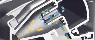
Cyclone oil separators (oil separators)
To get rid of the shortcomings of synthetic fiber filter fabric, cyclonic oil separators .
Rice. Operating principle of the engine crankcase ventilation system with a cyclone oil separator: 1 – cyclone oil separator; 2 – pressure regulation valve; 3 – charge air cooler; 4 – turbocharger; 5 – gases breaking through the piston rings
Crankcase gases are supplied through a channel inside the engine into a cyclone oil separator. The cyclone oil separator causes the air to rotate. Due to the resulting centrifugal force, the oil mist hits the wall of the oil separator. Drops of oil form there, which flow through a channel in the crankcase into the oil pan. The air, cleared of oil mist, is supplied to the air intake duct through the pressure control valve.
We recommend: Tire load index - meaning of symbols
The cyclone oil separator is equipped with a special valve that limits the vacuum in the engine crankcase, since a strong vacuum can damage the engine oil seals and other rubber seals.
Rice. Diagram of operation of the cyclone oil separator pressure control valve: 1 – crankcase gas supply pipeline; 2 – air intake pipeline; 3 – membrane; 4 – compression spring; a – open position of the valve; b – valve closed position
The pressure control valve is located in the cover of the cyclone oil separator. It consists of a diaphragm and a compression spring and regulates the pressure when air is removed from the crankcase. The pressure control valve closes when there is a strong vacuum in the intake channel. When there is a slight vacuum in the intake channel, it opens by the force of a compression spring.
Oil separator operation
The oil separator, which is an important element of the crankcase gas recirculation system, can operate according to one of two basic principles:
- labyrinthine;
- cyclical.
Using the labyrinth method, the speed of crankcase gases decreases. Due to this, larger drops of oil remain on the walls of the device, and then fall back into the engine crankcase.
Passing through the cyclic oil separator, the gases begin to rotate. Thanks to the centrifugal force generated in the device, oil drops settle on the walls of the oil trap, after which they flow by gravity into the crankcase. And to eliminate gas turbulence, a labyrinth crankcase oil separator is used, in which the oil becomes completely separable from the gases.
Signs of malfunction
- Excessive oil fogging in places of rubber seals. It is pointless to change the cylinder head gasket, pan or oil seals without eliminating the cause of the increased pressure of crankcase gases. The reason may be either insufficient crankcase ventilation performance or critical wear of the cylinder-piston group (hereinafter referred to as the CPG). In the latter case, more crankcase gases leak into the pan than the crankcase ventilation system can pass through. On cars with a synthetic filter element, we first recommend checking the condition of the filter.
- Excessive oil consumption. Increased pressure in the crankcase prevents the oil scraper rings from working effectively, causing oil to burn in the cylinders.
- Floating idle speed. The reason is a leak in the system. Cracks in hoses, PCV valve body, loose clamps - all these factors lead to the leakage of unaccounted air.
- Persistent smell of exhaust gases when driving at low speeds and while parked with the engine running. The closed crankcase ventilation system is leaky in the section up to the VCV valve, which is why gases break into the engine compartment, from where they are drawn inside the car by the cabin fan.
- A large amount of oil in the intake manifold, pipes and even on the air filter. The reason is a faulty oil trap.
Crankcase gas valve: from history
We examined the principle diagram of the operation of a forced ventilation system. As noted above, the design is based on a special valve responsible for recirculating gases. This is a simple device that helps reduce the level of harmful substances. The need for these devices was first discussed in the 70s. It was during this period that people began to think seriously about the environment and the harmful effects that exhaust gases had on it. Due to the use of a recirculation valve, crankcase gases are burned out in the cylinders. This is how various harmful impurities, oil and other substances burn.
The crankcase gas valve has been significantly changed several times over 15 years. Engineers changed its structure and operating principle. In 1977, a mechanical design with positive back pressure was developed and applied. After 2 years, in 1979, it was replaced with the same mechanical valve, but with negative back pressure. In 1988, discrete valves with three solenoids began to be introduced. Since the 90s, discrete devices with two solenoids have been actively used. This mechanism can control the flow of gases through one large and one small hole. This provides three different flows. This design turned out to be the most reliable and is successfully used even now on modern cars (for example, the Kia Sorento crankcase gas valve).
Consequences of faulty crankcase ventilation
Consequences of high pressure in the crankcase:
- Damage to the rubber seals of the crankshaft and camshaft. The engine will lose oil through squeezed out oil seals. If a sharp decrease in level is not noticed in time, oil starvation can lead to wear of the rubbing pairs and rotation of the liners.
- Turbine failure. After lubricating and cooling the turbocharger parts, the oil should drain by gravity into the pan. If there is a backlash of gases in the crankcase space (a kind of plug), the volume of engine oil pumped through the turbine will sharply decrease. Due to deterioration of heat dissipation, the oil will begin to coke inside the channels and on hot rubbing vapors. The consequence is scuffing on the liners and turbine shaft, which is equivalent to a deep restoration or replacement of the cartridge/turbocharger assembly.
- Squeezing out the dipstick and splashing oil into the engine compartment. In some cases, the dipstick flies out with such force that it leaves a noticeable dent in the hood. In this case, you won’t be able to get rid of it just by washing the engine compartment.
Diagnostic methods
The easiest way to check the PCV valve is by yourself. To do this, just blow into the valve from the side of the valve cover. If the air pressure from the reverse side is weak or does not come out at all, the valve is not working properly. Cleaning the crankcase ventilation system with carburetor cleaner should correct the situation. If the valve is blown in both directions, most likely it is stuck in a half-open state, or the rubber membrane is torn.
The degree of contamination and the overall efficiency of the crankcase ventilation is measured in two main ways:
- The crankcase gas pressure is measured at different engine operating modes.
- The volume of gases that the system can pass through itself is measured.
In order not to encounter the consequences of malfunctions of the VKG system, it is worth periodically changing the PCV valve, filter element, and cleaning the centrifugal/labyrinth oil trap.
What might you need?
There is no need to immediately run to the store in search of a miracle device, because you can make it yourself, unless you buy the necessary “ingredients”. So, for home production of a crankcase gas oil separator on a VAZ-2109 (for example), you cannot do without:
- repair coupling;
- plugs for the socket (2 pieces);
- plastic pipes (also 2 pieces);
- metal sponge.
A repair coupling is sold at any hardware store and is used when carrying out sewer work. It is a plastic cylinder, which at both ends has a small thickening on the outside with a rubber seal. The remaining components can also be purchased both at construction sites and in stores selling household goods. As for the cost, it is quite affordable and affordable for any family budget. The metal sponge will serve as the main element of the entire system.
How to repair
In old domestic cars, the factory installed a so-called “breather” to solve the problem. It was direct-flow, constant action. You just had to monitor its frequency. Periodically disassemble the structure and wash it from oil deposits.
Engine crankcase ventilation system on domestic cars with breather
Modern cars have not come far in terms of system maintenance. It is necessary to periodically check its operation as described above. In case of problems or failures, we clean all elements. They are, in most cases, removable, can be washed with gasoline, dried and reinstalled.
The crankcase ventilation valve on many models is repairable. Let's take it apart and check why it jams. If it is “overgrown” with oil deposits, then wash it. If there is mechanical damage, we replace it.
Sources
- https://AvtoMotoProf.ru/obsluzhivanie-i-uhod-za-avtomobilem/ventilyatsiya-kartera-dvigatelya/
- https://lada-xray2.ru/sovet/kak-sdelat-masloulovitel
- https://autolirika.ru/teoriya/ventilyaciya-kartera.html
- https://santavod.ru/kak-proverit-klapan-ventilyaczii-karternyh-gazov-pcv/
- https://FB.ru/article/341878/maslootdelitel-karternyih-gazov-svoimi-rukami-opisanie-shema
- https://zen.yandex.ru/media/id/59ab872ae86a9e96d63241ad/ventiliaciia-kartera-dvigatelia—chto-eto-takoe-i-pochemu-ona-tak-vajna-dlia-motora-5e8b1a2482d52277064cd412
- https://www.autoposobie.ru/kak-sdelat-masloulovitel-svoimi-rukami/
- https://avto-idea.ru/remont/kak-sdelat-maslootdelitel-svoimi-rukami-materialy-i/
How to clean
To begin work, you will need to prepare the necessary tools, namely:
The crankcase ventilation of a VAZ 2114 is cleaned as follows:
- Loosen the fastening clamps of both pipes and then remove them.
- Inspect the pipes for cracks or chips - if the latter are present, replace the pipes with new ones of the same diameter.
- If the pipes are in good condition, clean them outside and inside with a damp cloth.
- Disconnect the throttle cable from the sector.
- Remove the pair of mounting bolts securing the throttle body to the receiver.
- Remove the bracket along with the cable.
- Unscrew the two bolts securing the cylinder head, and then remove the washers and rubber bushings located on them.
- Remove the cylinder head cover itself.
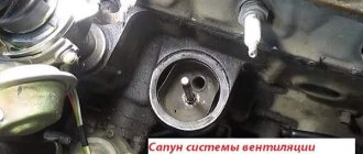
- Find the oil separator on the cylinder head cover and unscrew the mounting bolts that hold it.
- Remove the housing cover, and then remove the oil separator itself.
- Thoroughly rinse the filter mesh (oil separator) in gasoline (it is recommended to use highly purified gasoline for this) or kerosene.
- Clean the cylinder head cover from oil and adhering dirt (this is best done using a rag soaked in kerosene).
- Install the oil separator filter back into the cylinder head cover.
- Reassemble in exactly the same order, but in reverse order.
To avoid possible injuries, all work on dismantling the cylinder head cover and cleaning the ventilation system should be carried out only with the engine completely cooled.
It should be noted that when performing operations to clean the ventilation system, it is worth paying attention to the condition of the rubber bushings that fasten the cylinder head, as well as the gasket. If they are worn out or covered with cracks, they should be replaced immediately, without waiting for serious damage.