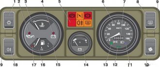
The elements are connected to instruments or controls: 1 – button for the heated rear glass switch; 2/6 – fog light switches, for rear/front module; 3 – plastic block for activating head optics and turn signals; 4 – fuse block; 5 – wiper mode switch; 7 – on-board system indication; 8 – supply voltage to the additional harness; 9 – dashboard; 10 – “male” for powering the on-board computer; 11 – terminal to the ignition device; 12 – for door wiring; 13/14 – fuses; 16 – ignition break; 17 – stove motor; 18 – secondary resistance of the stove; 19 – current supply to the ignition unloading relay; 20 – protective relay for rear fog lights; 21 – starter fuse relay; 22 – remote socket for a portable lamp; 23 – power supply for the cigarette lighter; 24 – for illumination of the glove box; 25-27 – illuminators; 28 – stove switch; 29 – tidy lighting with rheostat; 30 – stop switch; 31/32 – horn/hazard warning switch, respectively; 33 – backlight of the stove panel; 34 – fuse; 35 – protective relay for seat heating elements; Ш1/4 – mounting block jumpers; X1/2 – dashboard controls; A – protective ground output (usually black).
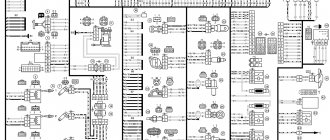
Electrical equipment of the front of the car
The following is a breakdown of the front cable bundle, excluding fog lights:
- 1 – output terminals of the starter contact group;
- 2 – battery, connection of power cables;
- 3 – standard “father” of the generator;
- 4 – blocks for connecting the power conductors of the battery and generator to the front assembly of electrical equipment;
- 5 – part of the fuse mounting block;
- 6 – standard horn;
- 7 – sensor that measures the temperature of antifreeze in the power plant;
- 8 – standard sensor for measuring the washer fluid residue in the tank; when activated, the corresponding indicator on the device lights up;
- 9/10 – left and right headlights, respectively;
- 11 – external thermometer;
- 12 – standard reverse gear lamp switch;
- 13 – drive of the electric fan of the generator;
- 14 – connector to the ignition system module;
- 15 – in the VAZ 2114 scheme the injector is not used, it is used only for the carburetor;
- 16 – electronic brake fluid level sensor; in case of a critical drop, an exclamation mark lights up on the instrument panel;
- 17 – built-in oil level sensor in the crankcase compartment of the power plant; when activated, the red light on the instrument panel lights up;
- 18 – similar for the engine cooling system;
- Ш5-8 – mounting block connectors;
- A1/2, B1/2 – grounding terminals.
Diagram of low beam, high beam, rear fog lamps
- Headlights;
- Mounting block;
- Headlight switch;
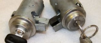
- Ignition switch;
- External lighting switch (fragment);
- Fog lamps in the interior rear lights;
- Fog light switch with turn-on indicator lamp;
- Headlight high beam indicator lamp in the instrument cluster;
- K8 - High beam headlight relay;
- K9 - Relay for low beam headlights;
- A - The order of conditional numbering of plugs in the headlight block;
- B - to power supplies.
Wiring diagram VAZ 2114 injector: decoding of rear harness contacts
Here are the conclusions of the equipment located in the rear of the vehicle:
- 1 – output of the mounting unit;
- 2 – windshield heater;
- 3 – electric drive of the rear wiper gearbox;
- 4 – diodes for illuminating the stern license plate;
- 5 – license plate illuminator directly, some users connect diode strips here for better lighting;
- 6/7 – illuminated direction indicators, for the left and right sides, respectively;
- 8 – lamp for individual illumination of useful space;
- 9 – interior lighting lamp, usually located in the ceiling, above the steering seats;
- 10 – handbrake lever position indicator;
- 11/12 – left and right side lighting lamp;
- 13 – power supply to the additional brake light indicator;
- 14-17 – group of interior lighting switches located in the door pillars;
- Ш9 – terminal block of the fuse mounting device;
- A1 – license plate grounding;
- A2/7 – standard grounding points.
Diagram of side lights, brake lights, interior lighting
- Side light bulbs in headlights;
- Engine compartment lamp;
- Mounting block;
- Engine compartment lamp switch;
- Ignition switch;
- External lighting switch (fragment);
- External lighting indicator lamp in the instrument cluster;
- Lamps for side lights and brake lights in the outer rear lights;
- License plate lights;
- Instrument lighting regulator;
- Brake light switch;
- On-board control system unit;
- K4 - Relay for monitoring the health of lamps (contact jumpers are shown inside the relay, which must be installed in the absence of a relay);
- A - to power supplies;
- B - to the backlight lamps of switches and devices;
- C - to an additional braking signal.
Electrical connection diagram for VAZ 2114, additional segment
Here are grouped auxiliary equipment that is not related to the power plant or on-board computer of the car:
- 1 – contact group of wiring from the doors to the instrument panel block;
- 2 – a similar terminal intended for connecting heated seat devices for the driver and front passenger;
- 3/4 – central locking drive, sections of the front left and right doors, respectively;
- 5/6 – contact blocks of the front right and left speakers, respectively;
- 7 – electronic central locking control unit;
- 8/9 – connecting door parts of electrical equipment to the auxiliary left beam;
- 10 – terminal for connecting the standard speaker system;
- 11 – “mother” of doors to the right wiring harness for connecting electrical equipment;
- A1 – connection of grounding electrical wiring.
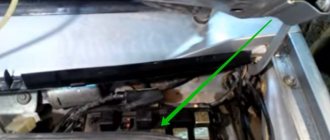
Physically, the output is connected to the dashboard, with a contact group located near the hood opening handle. The corresponding fuse is also located here.
Peculiarities
VAZ 2114 cars have many innovations compared to 2109, in particular, this concerns electrical wiring.
Whether it is an injector or a carburetor, the wiring diagram for the VAZ 2114 is located in:
- vehicle interior;
- in the engine compartment;
- behind the car body.
It should be noted that carburetor VAZ 2114 were produced only from 1997 to 2000, then they were equipped with carburetors from the VAZ 2108.
But new engines have a more powerful ignition system; accordingly, the electrical control circuit is also characterized by certain features, for example:
- There is a new harness for connecting to the ignition module terminal. This component sends signals to the spark plugs through high-voltage wires.
- Another harness was added to allow mounting of the switch.
- Additional wiring has appeared to connect the adsorber valve to the injection system controller.
Wiring and equipment diagram 2114
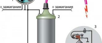
Many VAZ 2114 car owners mistakenly believe that thanks to the ignition module, they don’t have to use a coil. In fact, this device is equipped with two coils and two switches. One of the coils transmits the signal to the first and fourth cylinders, and the second - to the second and third.
The equipment system of VAZ 2114 cars with an injector engine has undergone certain innovations not only due to the addition of new electrical equipment, but also as a result of modernization of the car as a whole:
- it is possible to install a heated side mirror device;
- you can connect the front seat heating system;
- VAZ 2114 car owners can install PTF, etc.
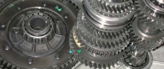
Engine compartment
So that a VAZ 2114 with an injector engine can operate on a lean combustible mixture, the car is equipped with:
- forced gasoline injection system into each individual cylinder;
- connecting an improved ignition system characterized by higher power;
- added ECM - injection engine control system.
BC display on a car dashboard
As is known, to ignite a lean combustible mixture there must be a more powerful spark transmitted through high-voltage explosive wires. A spark is transmitted through the explosives of the VAZ 2114 injector when the piston is located at top dead center. This control and connection scheme via high-voltage wires was implemented thanks to the installation of the module.
The operating principle of the device is as follows:
- a generator is used to generate alternating electric current;
- the current passes to the control unit, where it is converted into direct current;
- further, the current flows to the windings of the coils in accordance with the control circuit;
- the secondary winding begins to generate high voltage for transmission through high-voltage explosive wires;
- then, through the same high-voltage explosive wires, the voltage passes to the spark plugs.
Salon
As for the interior, the manufacturer replaced the center console in the VAZ 2114, which has certain differences:
- there is no longer a glove compartment in the upper part, it is installed lower;
- the dashboard was replaced;
- an on-board computer appeared in the VAZ 2114.
Diagnostics of resistance with a multimeter
As a result of such changes and the replacement of old elements with new ones in the VAZ 2114 with an injector engine, the control circuit and wiring connections have also changed:
- another harness appeared for connecting the on-board computer;
- a sensor for monitoring the temperature level outside the window has been added, which is mounted in front of the radiator;
- A voltmeter relay has been added.
In addition, another block of wires was added to the control circuit to control the power windows.
VAZ 2114 wiring diagram: section of the right front door
The cut is a simplified concept due to the minimal amount of equipment. The most budget version is completely absent.
- 1 – “mother” of the rear harness, suitable for the door wiring;
- 2 – power supply to the electric motor for the front passenger window;
- 3 – terminal block to the standard door speaker;
- 4 – door lock servo motor (part of the central lock);
- 5 – power switch and power window drive mode switch;
- A – grounding bus.
About wiring
VAZ 2114 wiring is a product that connects all electrical components of the car. Current passes through them and powers electrical equipment.
There are different requirements for wiring. Among them are strength and reliability . Wires are subject to friction, shock, shaking, ingress of fuel and oil, and temperature fluctuations. This entire product must withstand. Also, the electrical wire must be flexible and have high-quality insulation.
If the car's wiring is faulty, a short circuit and fire may occur, and electrical appliances will stop working properly. Determine which wires are faulty by testing them with a multimeter.
Wiring diagram VAZ 2114: driver's door
A larger section of standard on-board wiring:
- 1 – contact group for connecting to the wiring of the additional bundle;
- 2 – similar output to the aft left beam;
- 3 – electric window motor drive;
- 4 – standard output of the block to the front speaker of the standard acoustic system;
- 5 – door lock drive;
- 6/7 – power window control buttons, for left and right, respectively;
- A1 – standard protective grounding terminal.
Wiring diagram VAZ 2114 injector - a separate section of seat heating equipment
A specially dedicated section of on-board wiring responsible for powering, activating and adjusting seat heater devices. Here is a detailed description of all structural elements:
- 1 – driver’s seat heater;
- 2 – output to the terminal block of the dashboard;
- 3 – separate connector for the driver’s door, wire supply to the control button;
- 4 – heating element of the front passenger seat;
- 5/6 – adjustment key for the element specified in paragraphs No. 1 and 4;
- A1 – grounding wire, fastened with a bolt to the car body.
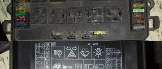
Mounting block connection diagram
The outer number in the designation of the wire tip is the number of the block, the inner number is the conventional number of the tip.
- K1 - Relay for turning on headlight cleaners;
- K2 - Relay interrupter for direction indicators and hazard warning lights;
- Short circuit - Windshield wiper relay;
- K4 - Relay for monitoring the health of lamps;
- K5 - Relay for turning on power windows (in a variant version of the car);
- K6 - Relay for turning on sound signals;
- K7 - Relay for turning on the heated rear window;
- K8 - Headlight high beam relay;
- K9 - Relay for low beam headlights;
- F1-F16 - Fuses.
Pinout of on-board computer VAZ 2114
In standard drawings of electrical equipment, the BC block section is missing due to its uselessness. Initially, it is assumed that the motorist will not independently repair or maintain the complex control unit. But some users still take risks and install the system themselves. In older versions of cars, such a module is missing or insufficient for comfortable operation of the car in its modern form.
To connect wires to the module, you will need to buy a standard 9-pin header and connect the following wires to it:
- 1 – green wire comes from the fuel consumption sensor;
- 2 – the ignition cylinder is powered through an orange cable;
- 3 – power core from the battery, usually a red wire with a white stripe is supplied;
- 4 – grounding or ground, standard color – black;
- 5 – 6k line, usually a gray wire;
- 6 – Mute – green shell with a red line;
- 7 – the backlight in the standard pinout is output from the marker optics key;
- 8 – a sensor that displays the remaining fuel in the car’s gas tank can be connected directly.
How to prevent electrical equipment breakdowns?
In order for the VAZ 2114 pinout to be required as rarely as possible, the user is required to follow a number of simple rules and recommendations.
- Periodically treat all metal parts with special oil. In this case, it is first necessary to clean the copper patches from oxides and traces of corrosion. Such lesions provoke a deterioration in the transmission of signals, which can be perceived by the car as a breakdown.
- Every 20-30 thousand kilometers, check all equipment and plastic plugs for looseness or reduced fastening rigidity. With constant vibrations typical of vehicles, plastic clamps can fail and cause breakdown.
- Monitor the correct battery charge and the serviceability of the generator. Some machine devices do not work correctly when there is a strong voltage drop.
- Every 40,000 km, check the condition of the wires themselves. With constant use, the braids of the power cores may crack or dry out, which increases the likelihood of a short circuit in the on-board lines. This may also cause a fire.
Basic faults
If malfunctions occur with high-voltage explosive wires or wiring in general, this will be reflected in:
- on the functioning of the engine - the unit will not be able to operate at full power;
- on the functioning of the equipment;
- on the operation of optics and other systems.
In general, wiring faults are divided into several types - breakdowns of the ignition system and sensors. Depending on the type, the diagnostic procedure is determined. In order for the order to be correct, you first need to understand the type of malfunction.
Ignition failures
Repairing the ignition module
Signs of malfunctions in the injector control circuit, which will help determine the course of action:
- loss of engine power;
- the appearance of dips in power when you press the gas;
- unstable idle speed;
- incorrect operation of one or more cylinders.
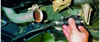
The procedure for identifying a breakdown begins with diagnosing the presence of a spark in the explosive wires:
- the ignition is turned on;
- it is necessary to remove the tip from the explosive wire of the first cylinder;
- the tip must be brought close to the metal, but not pressed (the distance between the tip and the metal is about half a cm);
- then the starter turns on and you check if there is a spark, a similar operation is repeated with all the spark plugs (the author of the video is Home Auto Repair. Car Repair.).
If there is no spark, you need to look for problems in the coils or generator circuit, the procedure is as follows:
- the coil is diagnosed;
- module is checked;
- then you need to check the control unit.
In this case, the resistance is measured. A tester is used to diagnose coil resistance. You need to measure the resistance of the primary and secondary windings. The resistance level must be correct; if the resistance is incorrect, the windings may need to be replaced.
As for diagnosing the module, it is also done using a tester - you need to measure the resistance on the paired explosive wires. The resistance level should be 5.4 kOhm. If the resistance is different, then you have found the cause of the breakdown.
Sensor failures
As you know, cars of this model are equipped with multiple sensors, the failure of which can also cause unstable engine operation. Since wiring in the engine compartment can cause problems in the operation of the unit, you should try to move the pads and connectors before changing the sensors. Perhaps the problem is a poor connection.
Most regulators can be checked using a tester; as a rule, sensor failure is indicated by the Check lamp on the control panel. As for regulators such as idle speed and mass air flow, you can find out about their failure after diagnostics, which is carried out using the shutdown method. If the engine does not start at all, you need to check the crankshaft sensor.