Hello, dear friends! I think many people are interested in an effective connection diagram for DRLs, that is, daytime running lights.
For several years now, there have been rules in the country according to which, when driving a car during the day, you should indicate your presence with the help of appropriate headlights. Fog lights, low beam headlights and the DRLs themselves are used as such lamps.
The use of fog lights and headlights has objective disadvantages. Therefore, it is best to connect the DRLs from the generator or battery yourself.
There are various ways and schemes for implementing the idea. Some do this without a relay, others combine DRLs with turn signals, others even control the daytime lights with a separate button, etc. To do everything right, you need to know some important points. And then automatic activation will be carried out without violating traffic rules.
Hitch and coupling head: what is what and what they are like
The regulations state that the circuit should be used in such a way that the drive wheels turn on automatically when the key is turned in the ignition switch. That is, when starting the power plant. But DRLs are also required to turn off automatically as soon as the main beam headlights come on. Here, as you understand, we are talking about the headlight unit (low or high beam). There is also a rule indicating that the head light should turn on only when the headlights turn on. The exception is short-term signals to warn other drivers.
Based on the above, we can safely say that you should not output the DRL through the button. The same as through the handbrake. But you can install it in turn signals, but you will need to connect 2 additional wires from each turn signal.
All this is extremely important to take into account when connecting the movers. After all, you should be concerned not only with the fact that the light bulbs do not burn out. Although this is an extremely significant point.
Without a well-thought-out and competent scheme, you will definitely not be able to install DRLs yourself. After all, everything should work with a shutdown when the high or low beam is turned on.
There are a number of schemes according to which, in theory, you can install DRLs on your car if they are not included in the standard configuration of your vehicle. The only question is which scheme is better to use.
An important role is played by the voltage stabilizer, which is a subject of much debate when using diode running lights. The DRLs themselves are equipped with resistors that act as a current limiter. But during voltage surges, they are not able to maintain the voltage at a single level. Therefore, it is correct to assume that the use of a stabilizer in such a scheme will be mandatory and necessary. Otherwise, the service life of the DRL will be significantly reduced due to regular voltage drops. Although some still believe that the connection can be made without a stabilizer.
It is worth considering several schemes separately, drawing appropriate conclusions from them and making a final decision for yourself.
Legislation
Before practicing installing DRLs, I would like to dwell a little on the legal standards for installing DRLs, as well as the rules of their operation.
The very first and basic rule is that unauthorized installation of additional light signals on a car is prohibited. Yes, you are right, you do not have the right to install DRLs on your car if it was not equipped with them by the manufacturer. This will be considered as making changes to the design of the vehicle. For every change to a vehicle's design, a certificate must be obtained, which in itself is neither quick nor cheap. Otherwise, traffic police officers will issue you a fine, or even take your car to the impound lot.
How so? My neighbor installed DRLs on the Oka and drives calmly! - you ask. He is simply lucky to have loyal traffic police officers who do not pay attention to his DRL - I will answer you.
Once again, unauthorized installation of additional light signals on a car is prohibited if it was not equipped with them by the manufacturer. Therefore, you make any changes to the design of the vehicle at your own peril and risk. It’s a completely different matter if your car’s equipment does not include DRLs, but the more expensive trim levels of your model do have DRLs. In this case, you have the right to install DRL without any approval from the certifying authorities.
The first rule for installing DRLs concerns their location on the car body (see picture). If we briefly describe this figure, we get the following:
- DRLs should be installed at a height of 250 to 1500 mm;
- The distance between adjacent edges of the DRLs must be at least 600 mm;
- The distance from the outer side surface of the vehicle to the nearby edge of the DRL should be no more than 400 mm.
Now let’s briefly go through the rules of operation and use of DRLs:
- DRLs should only be used during daylight hours;
- It is prohibited to use DRLs in conjunction with side lights, low and high beam headlights, as well as fog lights.
Everything that is not prohibited is permitted. It's that simple. Separately, I would like to dwell on an important point, it concerns the use of DRLs in conjunction with high beam headlights. The rule goes something like this: When the high beam signal is briefly signaled, with the side lights and low beam headlights turned off, the DRLs should not turn off. Let me break it down: you are driving with your headlights and side lights turned off, your DRLs are on, when you signal with your high beams to an oncoming car that you are approaching a traffic police post, your DRLs should not turn off.
Just? I also think that there is nothing complicated here. Knowing the legislation and rules for using DRLs, we are ready to move on to the practice of connecting them. Let's start with the simple and incorrect and end with the complex and correct. Go!
It couldn't be simpler
This is the simplest scheme, which involves connecting to a battery or generator as a power source.
The scheme provides that the DRLs will be activated simultaneously with the engine starting. The point is to connect the plus to the positive terminal from the ignition switch of your Renault Logan or the same Lada Largus, and fix the minus on the car body in any convenient place. Everything looks simple and extremely logical. But you should not rush to conclusions, nor should you make such a connection. After all, it has an obvious drawback.
If the system is assembled according to this scheme, the diodes from the DRLs will start working constantly while the key is in the ignition switch. There is no question of any coordination with other headlights here. Therefore, such a connection contradicts GOST and traffic regulations.
Eventually
The daytime running lights are connected to the vehicle’s on-board network via either a four-pin relay or a five-pin one. In this case, the “+” of the power circuit is taken from terminal D of the generator. In this state of affairs, the headlights are activated when the engine is turned on. The relay allows you to turn off the LED lights when the side lights are turned on. In particular, you can turn off the running lights when you turn on the low beam by taking the “+” from the positive contact of the low beam instead of the “dimensions”.
Source
Low beam or dimensions
You can also connect to the side lights or low beam headlights. In theory, everything here also looks quite simple, interesting and promising. The first of the schemes under consideration provides that you will use an electrical circuit that powers the size lamps. Here the plus from the DRL is connected directly to the battery as a power source. But the minus goes to the plus of the dimensions. At such a moment the latter will be electrically neutral. Thus, the current flows from the plus of the battery through the diodes to the dimensions, and then through the lamp to the housing, where the latter acts as a minus of the created electrical circuit.
Since the level of current consumption will be small, the diodes will start to work, but the size lamp will not turn on.
As soon as the driver switches to the dimensions, a voltage of 12V will appear on its positive side, the potentials will be equalized on the DRL wiring and the diodes will go out. The circuit will begin to operate in normal mode, supplying current to the dimensions.
Everything seems to be fine. But again, conclusions were drawn hastily.
The scheme is simple and working. It just has a few drawbacks:
- The drive trains will remain active when the engine is switched off. This directly contradicts current laws;
- If the dimensions are equipped with LED lamps, such a circuit will immediately become inoperative;
- Operation will not be correct when using powerful SMD diodes as part of DRLs;
- To provide additional safety, you will have to add a fuse to the circuit.
To avoid the first drawback, the circuit is slightly altered. The positive from the LED module is taken not from the positive of the battery, but through the positive of the ignition switch.
The second scheme involves activating the DRL using a low beam lamp. The point is that when the low beam is turned on, the walkers are turned off, and the rest of the time they work.
There are the same disadvantages here as for the previous scheme. That is, it contradicts GOST and traffic rules.
The essence of modernization
The technology of connecting DRLs from a car generator did not arise by chance. After all, the main GOST requirements for the functioning of DRL are as follows:
- powerful light-emitting diodes must be turned off when the head light is activated, which is the “near”, “far” or luminous flux from the PTF;
- DRLs should automatically start when the body that controls the engine operating modes moves to the “on” position;
- it must be possible to turn off the running lights without the help of an external tool, i.e. button.
How to remove an air lock from a car's cooling system: instructions
These are two more methods worth considering. A 4-pin relay, a generator and an oil pressure sensor will be used here. But not in a single chain.
Both schemes assume that the DRLs will turn on only when the engine starts. The system is powered by a generator and is based on switching a 4-pin switch and a reed switch.
The connection of the relay contacts looks like this:
- Pin 30 goes to the plus of the LED module;
- Contact 85 goes to the plus of the wire to the dimensions;
- Contact 86 is required for any output from the reed switch;
- 87 contact to the positive terminal from the battery;
- Also, the second terminal from the reed switch goes to the battery plus.
After connection, configuration must be carried out. Here you need to start the engine and start moving the reed switch near the generator in order to get the movement and stable operation of the movers. Then the reed switch should be removed into a special thermal tube and fixed.
If there is no reed switch, then power for the DRL can be supplied through the oil pressure sensor. Then contact 86 goes to the pressure lamp, but otherwise the circuit remains in its original form.
The schemes are excellent in many ways. But they cannot be used in situations where the dimensions are based on LEDs. This is the only significant drawback.
Connection via a 4-pin relay from a generator or oil sensor
The following two methods have a common basis and imply the operation of daytime running lights only after the engine is started. The circuit for switching on DRL from the generator is based on switching a four-contact relay and a reed switch.
The DRL relay contacts are connected as follows:
- 30 – to the positive terminals of LED modules;
- 85 – to the positive wire to the dimensions;
- 86 – to any reed switch output;
- 87 and the second terminal of the reed switch - to the “+” of the battery.
After checking the reliability of all contacts, proceed to setup. To do this, start the engine and, by moving the reed switch near the generator, achieve its activation and a stable glow of the DRL. Then the reed switch is hidden in a thermal tube and fixed in the found place using nylon ties.
At the moment of starting the engine, and then the generator, the contacts of the reed switch and relay close, supplying power to the LED running lights. In this case, the side lamps remain turned off, since the current through the relay coil is small to light them.
In the absence of a reed switch, you can power the DRL from the oil pressure sensor. In this case, pin 86 is connected to the oil pressure lamp. The rest of the circuitry is duplicated.
Both schemes have a common drawback. They cannot be used if LEDs are installed in the dimensions.
Mechanical air blower for a car: do it yourself
To get rid of the disadvantages of previous schemes, a connection option via a 5-pin relay is used.
The relay is connected as follows:
- Contact 87 is not connected and is simply isolated;
- 87a goes to plus to the ignition switch;
- Pin 86 is needed to connect to the housing;
- 85 goes to the positive wire from the side lights;
- Pin 30 is output to the plus of the DRL LED module.
By turning the key in the lock, 12V begins to flow to the DRL, which allows the running lamps to light. When turning on the headlights or headlights, the relay opens contact 87a and closes contact 87. Thus, the running gears turn off and the other lights turn on. This scheme is good because it complies with GOST and traffic regulations. Plus you can use diode dimensions.
Here it is recommended to use a voltage stabilizer. The only drawback of the scheme is that when you turn the key without starting the engine, the DRLs will light up.
DRL control unit
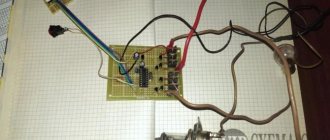
The most reliable and simplest option is to connect DRLs without a relay, but using a special running lights control unit. It ensures that the DRL turns on after starting the engine, guarantees safe operation, protects against overloads and can be installed on cars with any type of lamps, including LEDs.
Unfortunately, among the variety of industrially manufactured DRL units, the vast majority do not comply with GOST and have mediocre build quality.
This applies, first of all, to products from AliExpress, which do not meet the requirements in almost all respects.
Among all the diversity, only 2 options can be noted: the Russian DayLight+ DRL control unit and German products from Philips and Osram. The DayLight+ control unit was developed by Russian radio engineer Fedor Isachenkov, taking into account all the features of the vehicle’s on-board network and has a number of positive aspects:
- there is built-in voltage stabilization;
- full compliance with GOST;
- the maximum long-term load power is 36 Watts (significantly less is required for DRLs);
- simplest connection diagram.
In addition to the points described above, the DayLight+ unit is universal and is suitable for all cars with an on-board 12-volt network, and also has good build quality and a high degree of protection from moisture and dust.
German products from Philips and Osram also have all the above-described advantages of the DayLight+ unit, however, German control units are supplied only together with daytime running lights and are more expensive.
Write a comment
Comment:
Attention: HTML is not supported!
Hello, dear friends! I think many people are interested in an effective connection diagram for DRLs, that is, daytime running lights.
For several years now, there have been rules in the country according to which, when driving a car during the day, you should indicate your presence with the help of appropriate headlights. Fog lights, low beam headlights and the DRLs themselves are used as such lamps.
The use of fog lights and headlights has objective disadvantages. Therefore, it is best to connect the DRLs from the generator or battery yourself.
There are various ways and schemes for implementing the idea. Some do this without a relay, others combine DRLs with turn signals, others even control the daytime lights with a separate button, etc. To do everything right, you need to know some important points. And then automatic activation will be carried out without violating traffic rules.
Installation instructions
There will be no problems with the installation of purchased ready-made kits; the kit contains all the necessary elements for mounting. But if the lights are made independently, then you will need to pay more attention.
Connection diagrams for daytime running lights
Requirements for DRLs and according to GOST, the connection is carried out in such a way that when ignited, the lights turn on automatically, and when the main headlights are turned on, they turn off.
Using a generator, it is possible to connect according to three schemes:
- Using motor and RT:
- With an additional resistance resistor that will automatically turn off the source when the main lights are turned on:
- The on-board circuit automatically deactivates the source when the handbrake is lifted and the engine starts:
Installation locations
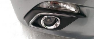
To ensure that traffic police officers do not have any questions and that the car undergoes successful maintenance, you need to know the correct placement of the DRLs:
- bottom of the radiator grille;
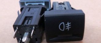
- main optical system;
- in places intended for fog lights.
The latter option is less in demand, since the owner usually prefers to install PTF.
There are also cars with installed running lights (LED strip) around the perimeter of the radiator grille, on top of it. Such options do not comply with safety rules, but are more considered an element of tuning.
Installation and connection process
The installation and connection stages consist of the following points:
- Selecting an installation location. Produced in accordance with the requirements and GOST.
- DRL installation. When installing on a radiator grille, it must be removed, washed and degreased. Apply double-sided tape to the attachment points, then attach the bracket.
It is recommended to carry out additional fixation with self-tapping screws.
Installation of the control unit. It is mounted near the battery, as far as possible from the engine, to avoid overheating. Next, the connection is made: a red wire is connected to the plus, a black wire to the minus; The orange wire is connected to the headlights (it is responsible for automatically turning off when the headlights are turned on).
Checking the connection. If the lights stay on for 20 seconds after the engine is turned off, this is normal. If everything works well, then the module is installed and the blocks are fixed in brackets. The wires are neatly hidden under the hood and secured. Replace the grate. Installation is complete.
Interesting video on the topic:
DIY control unit
If the car owner is versed in electronics, then the DRL unit can be assembled independently. When igniting, such a unit receives voltage, and the work is determined by the frequency of pulses from the ignition coil.
To connect:
- power is taken from any point when the ignition is on;
- the headlight input signal comes from the 12 V point;
- a current relay of more than 200 mA at 12 V is used at the output;
- The negative wire goes to ground.
Connecting DRL via generator
It is possible to power the DRL using a generator using a five-contact relay. The connection steps are shown in the diagram:
In addition to the relay, a button is used to connect to the circuit between the 30 relays and the generator.
Installation and connection to standard headlights
Running lights can be mounted in PTF. But for this you need to buy a 4- and 5-pin relay and make the connection:
- Contact 85 of the first relay is connected to ground;
- pin 86 goes to plus;
- contact 30 to 87 of the second relay;
- from 87 to plus headlight output;
- 86 second to the generator plus;
- 30 second with battery plus through the fuse;
- 85 second with mass.
With this connection, the PTFs will continue to work.
Scheme options
So, you can connect in several ways.
- The DRL turns on as soon as the ignition key is turned. The lights do not go out until the car engine stops. It is considered the simplest method, which does not involve the use of an on-board network. It is enough just to connect the negative from the lights to any place in the car body, and connect the positive from the lock to the output of the high-voltage module, always through a fuse.
- The same scheme, only the DRLs go out immediately as soon as the low beam is turned on. To implement this connection option, you need to adhere to the diagram described above, with the only difference being that the negative is connected to one of the positive wires of the low beam lamp. As soon as the low beam on the car is turned on, a positive impulse will appear on the minus DRL and the lights will go out. The DRLs will light up again as soon as the high beams are activated or the headlights are turned off.
- Connection diagram, which involves automatic connection of the DRL as soon as the car engine starts. It is considered the most reliable option for self-integrating LED daytime running lights. To implement this scheme, the minus of the DRL is connected to the car body, and the plus is connected to the relay contact.
Simple circuit with 4-pin relay
There is a simplicity in circuit number 1, implemented through a 4-pin relay. However, this option does not always satisfy the requirements of GOST, since the DRLs will shine separately from the head optics. The lights are not turned off by a push-button mechanism, everything happens automatically.
The photo above shows exactly this circuit, connected via a 4-pin relay. It implies the following procedure:
- when the engine starts, an impulse is sent from the generator to the relay, and the LEDs light up;
- As soon as the headlights are turned on, the DRLs turn off.
This connection method is also possible without using a generator. Then, instead, the voltage source will be the battery, the positive of which should be connected to the 30th contact in the photo.
It is also possible to connect the plus from the parking brake. In this case, as soon as the handbrake is activated, the daytime lights will go out - that's the button.
Circuit with 5-pin relay
It involves the use of 4 contacts. Ideal connection option for Priora cars. The difference from the above diagram is not only in the number of relay contacts. This circuit does not provide for the use of output 87. An alternative to ground is output 86.
The circuit with a 5-pin relay provides for the use of DRL control. The push-button mechanism is built between the generator and the 30th relay contact.
The operation of the DRL is as follows:
- the internal combustion engine is started, thereby the impulse from the generator goes to the 30th contact of the relay, and from there to the plus of the DRL;
- the lights come on, the minus is connected to any part of the car body;
- when the dimensions are used, the coil is activated, the 30th contact is integrated with the 87th, the pulse no longer arrives - the DRL is turned off.
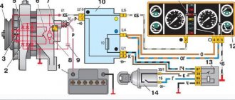
With reed switch
In a circuit using a reed switch, three important automotive systems are simultaneously activated: the generator, battery and relay.
The photo above shows a detailed connection diagram for the option using a generator. The plus is integrated, as can be seen from the diagram with point 30. The relay contact, marked with point 87, is integrated with the battery positive. Another relay contact, marked with number 85, is connected to the vehicle ground through the DRL.
Attention. This scheme implies the mandatory use of a reed switch - a device capable of changing the state of a connected electrical circuit when exposed to a magnetic field.
The contact marked on the diagram with point 86 is connected to the reed switch. From the reed switch there is a connection to the plus of the generator.
Thus, the scheme implies the following. As soon as the internal combustion engine starts, the driver activates the reed switch with a button, the relay is activated, and the DRL turns on. The reed switch must be packed in thermopolymer and securely fixed to the generator.
Advice. It is important that the reed switch is fixed exactly in the place of the generator where the relay would operate.
Without reed switch
A variation of circuit number 3, only without using a reed switch. In this case, the contact marked 86 is integrated with the oil pressure lamp in the instrument panel. Thus, the option of turning on the DRL after the engine is started is supported.
It is noteworthy that this scheme is much easier to implement with your own hands than the option with a reed switch.
Video: how to connect DRL from a generator
As you can see, connecting the DRL to the vehicle’s on-board network is carried out using several circuits. The plus is taken from the output of the generator, less often from the battery.
Forget about fines from cameras! An absolutely legal new product - Traffic Police Camera Jammer, hides your license plates from the cameras that are installed in all cities. More details at the link.
- Absolutely legal (Article 12.2);
- Hides from photo and video recording;
- Suitable for all cars;
- Works through the cigarette lighter connector;
- Does not cause interference to radios and cell phones.
LED neon tube
Two-color flexible tube
If you correctly install the flexible tape or tube inside the headlight, you will get decorative lighting that will look decent. You won't get DRLs from such a tube, even if you try hard.
The most difficult installation option, you will have to disassemble the headlight. The hardest part is removing the clear plastic from the front. The headlight is sealed and the glass is sealed. There are two types of sealant: one that softens at temperatures above 100 degrees, and one that does not soften at all even at 300 degrees. I came across non-separable ones, one took 10 hours to disassemble so as not to spoil or scratch it. I tested the sealant with a soldering iron, which heated up to 300° and could not melt it.
Bake until done and sprinkle with stewed nails
For heating, use an oven or box heated with a hair dryer. Once the sealant softens, the clear plastic will come off easily. For reassembly, you can buy a special rubber sealant, which is used by xenon technicians.
Choosing a stabilizer
In this form, the first and second methods will be combined. Even if your daytime running lights do not have a stabilizer, I recommend purchasing one or making it yourself.
You can buy Chinese modules at prices ranging from 50 to 120 rubles, so as not to order on Aliexpress, take a look at Avito, you can find very reasonable prices. The most common modules are pulse LM2596 and linear LM317. They are of course outdated, but they will draw a current of 1 ampere, which will be a power of 12 watts.
The XL6009, XL4015 chips are considered modern for 2016. They have higher efficiency and heat up much less. They can withstand a current of 2 Amps without a chip cooling system, this is equivalent to a load of 24 watts.