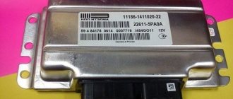
The engine control unit
One of the most important sensors in the UAZ system is the control unit for the entire engine; all sensors installed in the car transmit signals to it. Each of the sensors is directly connected to the block. The block processes the received readings and controls the engine. The ECU is one of the most expensive sensors installed in a car.
Signs of malfunction:
- All signs of ECU malfunction are similar to signs of sensor malfunction. Most often, the ignition system control keys in the ECU burn out and, as a result, one of the cylinders fails. This problem can be solved by re-soldering the key.
Finally, about the verification method
To perform a proper product check, you will need to acquire the following devices and accessories:
- Multimeter or regular voltmeter. Using these devices, it will be necessary to measure the voltage at the terminals of each sensor.
- Battery (12 V).
- A rheostat, which, after connecting with the battery, will produce a sensor supply voltage reduced to 5 Volts.
- An ammeter for measuring current.
Having assembled a simple diagram, we check the level of readings of the indicated parameters and compare them with the regulatory readings.
Below you can see a diagram of the connections of all components for checking the sensors.
Coolant temperature sensor
The coolant temperature sensor is used to measure the heating of the coolant. This is necessary to protect the engine from overheating; when certain temperature parameters are reached, the resistance on the sensor changes and the cooling fan turns on. The sensor is also responsible for the formation of the fuel mixture during a cold start. Coolant sensor type UAZ 19.3828 inside the sensor has a thermocouple, which, under the influence of temperature, changes its resistance and transmits it to the computer. The sensor is located in the thermostat housing.
Signs of malfunction:
- The cooling fan does not turn on;
- During a cold start, the engine stalls;
Maintenance
In order for this motor to work properly to the delight of its owner, it is necessary to carry out regular maintenance. Then, if this condition is met, the engine will have high performance. For this unit you need to use only high-quality fuel and lubricants.
All engine and vehicle systems need to be maintained and maintained. Only under such conditions will the motor last a long time and work without breakdowns. It is necessary to regularly check the oil and coolant levels, and the tension of the cooling pump belts.
In order for the engine to operate reliably, it is imperative to take care of the power system. Only with regular maintenance can stable operation be achieved. You need to be sure that all fuel line connections are secure, and you also need to clean the fuel injectors from time to time.
Crankshaft position sensor
The DPKV sensor is required for the ignition system. It reads readings from the crankshaft pulley and transmits them to the ECU, which sends signals to generate a spark in the cylinders. DPKV is the only sensor without which the car will not even start. The sensor is installed near the crankshaft pulley; its operating principle is based on a magnetic field; inside the sensor there is a magnet that counts the revolutions of the shaft.
Signs of malfunction:
- The engine does not start;
- One of the cylinders does not work;
Camshaft sensor (phase sensor)
This sensor is located on the cylinder head and serves to determine the position of the piston at TDC. This is necessary for the correct supply of fuel at the right time. If the sensor malfunctions, the fuel supply goes into pair mode, which leads to improper engine operation.
Signs of malfunction:
- Engine detonation;
- High fuel consumption;
DVTV
Replacement algorithm:
- We install the UAZ Patriot on a flat area, with an inspection channel available. We squeeze the parking brake for safety reasons;
- Open the hood and remove the power terminals from the battery. This is necessary in order to prevent short circuits in the circuit during work;
- On the left we unscrew the plastic cover, providing unhindered access to the measuring device;
- Using a Phillips-head screwdriver, unscrew the DVTV and remove the end switches;
- We install a new one in place of the standard sensor, put on the terminals again;
We start the engine and check the functionality of the measuring device. Do-it-yourself equipment replacement is complete.
Knock sensor
This sensor is designed to detect noise and detonations in the engine during operation. The principle of operation is similar to a piezoelectric element; when vibration occurs on the sensor, it generates a certain amount of voltage, transmitting it to the ECU, thereby indicating that there is detonation in the engine. The sensor is installed on the cylinder block near the 4th cylinder.
Signs of malfunction:
- High fuel consumption;
- Uneven operation of the internal combustion engine;
Engine sensors 406, 405 Gazelle, ZMZ 409 UAZ, UMZ 4213, 4216
Share:
This article describes all engine sensors 409, 406, 405, 4213, 4216, which are installed on UAZ and Gazelle vehicles of various modifications. Their technical characteristics, designs and methods for checking the serviceability of sensors are given. Electrical wiring diagrams for connecting engine sensors 409, 406, 405, 4213, 4216 are posted.
- Video - crankshaft sensor (DPKV) 409, 406, 405, 4213, 4216 engine
- Video - throttle valve sensor (TPS) 409, 406, 405, 4213, 4216 engine
- Video - camshaft sensor (DPRV) 409, 406, 405, 4213, 4216 engine
Location of sensors on the 409, 406, 405, 4213, 4216 engine: The engine sensor is an electromechanical device with a special sensitive element for collecting various state parameters of the 409, 406, 405 engine. Sensors and electromechanical actuators are installed on engines 409, 4213, 4216 and 406, 405. The sensors are used to collect information from the engine, fuel and exhaust systems by the car's computer (Electronic Engine Control Unit) in real time. After processing them, the ECU (Electronic Control Unit) transmits the necessary commands to the electromechanical actuators. With their help, the engine is controlled. Video - engine sensors 409, 406, 405: Other videos on engine sensors Connecting engine sensors 409, 406, 405, 4213, 4216 on a UAZ and Gazelle car: Catalog numbers of engine sensors and what they mean: It helps to buy and install those devices that suit your engine. This is a kind of hint for the driver about whether the specified electrical sensor is suitable for him or not. Whether it is replaceable or not with its original meter. Let's look at this designation system in catalogs using the example of an oil pressure indicator. The catalog number of the oil pressure meter is 23.3829010. The designations of assembly units and parts are numbered according to a unified seven-digit system. For example, the pressure indicator has the designation: 23.3829010, where:
- 23 - the first digits before the dot indicate the model of the unit;
- 38 - the first two digits of the seven-digit number after the dot mean the group number, in this case “Device”;
- 29 — the second two digits of the seven-digit number mean the subgroup number, in the current case “Oil injection device”;
- 010 - the last three digits of the seven-digit number indicate the serial number of the part, in this case “Oil pressure indicator”.
- To indicate the replaceability or non-replaceability of parts or assembly units, after their designation, digital indices are introduced that indicate that changes have been made to the design of the spare part or assembly unit. These numbers are indicated after the seven-digit number, after the dash. 01 - first interchangeable version;
- 02 - second replaceable option;
- . . . . . . . . . . . . . . . . . .;
- 09 - ninth interchangeable version;
- 10 - the first non-interchangeable variation;
- 11 - the first interchangeable option of the non-interchangeable variation 10;
- 12-19 - subsequent interchangeable variations of non-interchangeable variation 10;
- 20 - second non-replaceable version;
- 21-29 - interchangeable options of the second non-interchangeable option 20, etc.
Engine crankshaft sensor It has another name - engine timing sensor.
It is designed to determine the position of the crankshaft at any time during engine operation. The crankshaft sensor works in conjunction with the timing disc. Using these devices, the car's ECU determines the TDC of all engine cylinders. The beginning of the 20th tooth of the synchro disk corresponds to TDC of the first cylinder of the engine. Video - crankshaft sensor (DPKV) 409, 406, 405, 4213, 4216 engine: Video: replacing DPKV
Video: checking DPKV
Read more detailed information about the synchronization sensor on the page: Crankshaft sensor
Knock sensor 18.3855 The engine knock sensor is a sensor for detecting increased knocking phenomena in the engine.
It converts detonation knocks into electrical signals and sends them to the vehicle's electronic control unit. The computer, using data from the knock sensor, adjusts the ignition timing in the engine cylinders. This sensor is installed on the cylinder block, between the fourth and third pots. This device is connected to the propulsion network using a two-pin socket. Its entire wire is placed in a shielding sheath. More detailed information about the knock sensor is presented on the page: Knock sensor Video: review of the knock sensor
Video: checking the knock sensor
Engine coolant temperature sensor
The intake pipe temperature sensor (air temperature sensor) (DTV) and the engine coolant temperature sensor (ECT) are the same sensors in design and characteristics. There are 2 of them installed on the engine. One stands on the air receiver (if included in the engine configuration), and the second stands on the thermostat housing. On some engines, the air temperature sensor is combined with an air pressure sensor in one housing. Such a sensor is usually installed on top of the air receiver.
The internal combustion engine sensor is designed to measure the temperature of the engine coolant (Antifreeze) and send this information to the electronic control unit (ECU), converting the temperature into a DC voltage signal. The ECU, having received data from the DTOZH, calculates according to the program the required amount of fuel for injection by injectors into the propulsion pots during startup and during operation. If this sensor breaks, the computer will not correctly determine the size of the injected fuel. There will be an overflow or shortage of fuel and, as a result, the engine will not start and will perform poorly.
Interchangeability of DTOZH internal combustion engines
- Temperature sensor 19.3828 (t = 125°) ZMZ Euro-2 “PEKAR” / 19-3828000 is interchangeable with: Temperature sensor 19.3828 (t = 125°) ZMZ Euro-2
- Temperature sensor 40.5226 / 406.3828010. Note: This temperature sensor has been installed on 31602 with ECU 31602-3763010 for several years.
- Temperature sensor for PEKAR plug 40904-3828000
- Temperature sensor with MIKAS-11 "AutoTrade" (Kaluga) 421.3828 (analogue 234.3828)
Video: temperature sensor overview
Video: replacing the temperature sensor
Video: checking the temperature sensor
More comprehensive information about the coolant temperature sensor is presented on the page: Temperature sensor
Engine coolant temperature indicator sensor TM106-3808000-11 (TM106-11) Purpose and principle of operation of the temperature indicator sensor 406, 409, 405: It is designed to determine the temperature of the engine coolant and send data to the temperature gauge on the instrument panel. They are semiconductor resistors with a negative temperature coefficient of resistance. Their resistance decreases with increasing temperature of the coolant in the engine. Compared to metal thermistors, semiconductor ones have approximately ten times the temperature coefficient of resistance, that is, a change in temperature causes a sharp change in their resistance. The sensor is installed on a thermostat. It screws into a threaded socket. More detailed information about the coolant temperature indicator sensor can be found on the page: Engine coolant temperature indicator sensor Radiator (overheating) sensor TM-104
Design of the radiator (overheating) sensor TM-104 for the engine:
Designation in the picture:
- a - with flat thermobimetal;
- b - with a spiral;
- c - with a shaped heating element;
- 1 - body;
- 2 - thermobimetal;
- 3 - moving contact;
- 4 - fixed contact;
- 5 - heating coil.
Operating principle of coolant overheat sensors:
They use the property of a thermobimetallic plate to bend when heated. Such a plate consists of two layers of metal having different linear expansion coefficients. One passive metal (invar) increases less when heated than the second active metal (steel).
The thermobimetallic plate can be attached to coolant temperature measuring devices at one end or at two. When such a plate is heated, the steel expands more than the Invar and bends the plate towards the Invar. This property is used in overheating devices:
Designation on the diagrams:
- h1 is the thickness of the active layer of the plate;
- h2 is the thickness of the passive layer;
- L is the length of the heated section of the thermobimetallic plate;
- 1 — thermobimetallic plate;
- α1 is the linear coefficient of thermal expansion of the passive metal (invar);
- α2 is the linear coefficient of thermal expansion of the active metal (steel);
- 2 - moving contact;
- 3 - fixed contact;
- x is the amount of bending of the plate during overheating;
- 4 - pusher;
- Lthr is the threshold (maximum permissible) value of the coolant temperature.
Electrical diagram for connecting the radiator sensor (overheating)
Designation on the diagram:
- 1 - sensor;
- 2 - control lamp;
- 3 — ignition switch;
- 4 - fuse;
- 5 - ammeter;
- 6 - power supply;
- 7 — meter contacts.
Where is the radiator (overheating) sensor TM-104 located on the UAZ Simbir 31602:
Analogues of the radiator (overheating) sensor TM-104:
- TM-104-3808000/Kaluga/"AVTOPRIBOR"/UAZ, GAZ-53, 3IL-130K, -157KD
- TM-104-3808000/(coop.)/UAZ, GAZ-53, 3IL-130K, -157KD
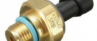
Emergency oil pressure sensor 4021.3829000(30.3829) Design of the engine emergency oil pressure sensor: Technical characteristics of the emergency oil pressure sensor 4021.3829000:
- Contact opening pressure: 0.4-0.8 kgf/cm2
- Contact closure pressure: 0.8-0.4 kgf/cm2
- Fitting thread of the piece: K 1/4″
- Electrical connection to the on-board network: 6.35 plug
- Maximum current load on contacts: 0.15 A
Analogs of emergency oil pressure sensor 4021.3829000:
- Emergency oil pressure sensor MM 111D** for terminal UAZ, GAZ, PAZ, ZIL, KrAZ, KamAZ "PEKAR" / MM111D
- Emergency oil pressure sensor MM 111V** for screw engines 402,4061,4063,40522,409, 40904,514″PEKAR”/MM111V “PEKAR” (analogue 29000-000)
- Emergency oil pressure sensor MM 111V** for screw engines 402,4061,4063,40522,409, 40904,514 (Penza) /6002.382929000-000)
Where is the engine oil pressure sensor located: The mounting location for the emergency oil pressure sensor 4021.3829000 is located on a special splitter screwed into a threaded socket in the engine head, behind the thermostat. this location is shown in the photo below: Checking the emergency engine oil pressure sensor 406, 409, 405: Checking the emergency engine oil pressure sensor in the following sequence:
- Remove the sensor from the car
- Assemble the circuit shown above in the figure
- Turn the electrical tester into resistance measurement mode
- Pump up the air pressure in the tee to 0.4-0.8 atmospheres
- At a pressure of 0.4-0.8 atmospheres, the sensor contacts should open and the electrical tester should show an infinite resistance value. In this case, the sensor is working. Otherwise, the sensor must be replaced.
Possible malfunctions of the engine oil pressure sensor 406, 409, 405:
- The emergency oil pressure indicator lamp should light up every time the ignition is turned on and the engine is not running. If the lamp does not light up, then the sensor may have failed, or there has been an open circuit in the circuit from the sensor to the signaling device. To check, disconnect the wire from the sensor and short it to ground. If the circuit is good and the sensor is faulty, the warning light on the instrument panel should light up.
- Constant lighting of the warning lamp when the engine is running (the control pressure gauge shows oil pressure above 1 kgf/cm2) may be the result of a malfunction of the sensor and a short to ground in the circuit from the sensor to the warning lamp. In this case, you should disconnect the wire from the sensor. If there is no short to ground and the sensor is faulty, the warning light on the instrument panel should go out.
- A properly functioning new sensor should operate at a pressure of 0.4...0.8 kgf/cm2. If the sensor response pressure decreases below 0.32 kgf/cm2 or increases above 0.96 kgf/cm2, the sensor must be replaced.
Mass air flow sensor (MAF) HLM2-4.7 0280212022 BOSCH engine
Purpose and principle of operation of the engine mass air flow sensor 406, 409, 405:
- The mass air flow sensor is designed to determine the amount of air entering the engine.
- The sensor's sensitive element is built on the principle of a thermistor anemometer. Which is made in the form of a platinum heated thread. The thread gets hot. Its temperature is maintained constant using electronic devices in the sensor design.
- When air passes through the air flow sensor, the filament cools down and the electronic device of the sensor increases the current to heat the filament to the previous temperature. More air increases the current and vice versa. The electronic device of the sensor converts current into voltage. The change in voltage is recorded by the ECU. Thus, more air increases voltage and vice versa
Design of the mass air flow sensor:
Technical characteristics of the engine mass air flow sensor:
- Power supply voltage - 8-16 V
- Current consumption no more than 1 A
- Range of measured air flow - 0-500 kg/h
- Resistance between pins 3-2 (output) 2.9-3.5 Ohm
- Resistance between pins 4-1 (burning) 20-25 kOhm
- Resistance between pins 6-1 (CO regulator) 0-1.0 kOhm
- When the ignition is turned on, there should be a voltage of 1.4±0.04 V at sensor output 3-2
- The resistance of the CO adjustment potentiometer is usually set to the middle position of 0.45-0.55 kOhm, one full turn of the screw is approximately equal to 0.035 kOhm, increasing the resistance is achieved by rotating the screw clockwise, decreasing it counterclockwise.
- The sensor has a non-linear dependence of the output voltage on the air mass flow: 15 kg/h: 2.3323…2.3599 V
- 30 kg/h: 2.6240…2.6572 V
- 60 kg/h: 2.9800…3.0214 V
- 120 kg/h: 3.4208…3.4820 V
- 280 kg/h: 4.1977…4.2711 V
- 480 kg/h: 4.7089…4.7857 V
Where is the MAF sensor located?: The MAF sensor is installed between the air filter and the throttle body. it is fastened with rubber sleeves with corrugations on clamps. The mass air flow sensor HLM2-4.7 0280212022 BOSCH is connected using a six-pin plug with a latch. An analogue of the mass air flow sensor HLM2-4.7 0280212022 BOSCH is:
- MAF sensor (MAF) UAZ PATRIOT (engine 409 Euro-0, -2) (6 pins), 316X “IMPULSE” ** / 3163-3877011 (IVKSH.407.282.000-01)
- MAF sensor (MAF) UAZ PATRIOT (engine 409 Euro-0, -2) (6-pin), 316X “PEKAR” / 407282000 (analogue 3163-3877011; 407.282.000)
Schematic electrical diagram for connecting the mass air flow sensor DMRV-M IVKSH.407282003:
Purpose of the terminals on the DMRV terminal block:
- Weight
- Minus from the ECU
- Plus from the ECU
- Burning
- Plus 12V from the relay
- PTSO from ECU
| Engine DMRV error codes 409.10 with Mikas 7.2: | ||
| Engine DMRV error code 409 | Fault name | Definition conditions |
| 013 | NUS Mass Air Flow Sensor | After starting the engine |
| 014 | VUS Mass air flow sensor | After starting the engine |
| 031 | NUS corrector CO | After turning on the ignition |
| 032 | VUS corrector CO | After turning on the ignition |
Accepted abbreviations in the error table:
- Short circuit - short circuit;
- IAC (RDV) - idle speed regulator (additional air regulator);
- EBN-electric fuel pump;
- CO concentration of carbon oxides in engine exhaust gases;
- RAM is an operational storage device;
- ROM is a read-only memory device;
- ICE internal combustion engine;
- EEPROM - non-volatile memory;
- VUS-high signal level;
- LUS-low signal level.
Malfunctions of the mass air flow sensor 407.282.000-01:
- Increased idle speed (1800±300rpm). The malfunction lamp lights up when the engine is running. Self-diagnosis of the unit records fault codes 13 or 14. Check the serviceability of circuits 6 and 7.
- Check circuit 36 (CO potentiometer) for serviceability
- Replace the air flow sensor
- Check and restore the serviceability of circuit 31 (thread burning)
Replacing the mass air flow sensor
- Remove the negative terminal of the battery
- Remove the electrical connector from the terminal block
- Loosen the metal clamps and slide them onto the rubber pipes to the left and right
- We remove the air flow sensor from the rubber pipes
- We insert the new mass air flow sensor into the rubber pipes, orienting it along the arrow. We focus on the movement of air from the air filter to the engine
- We slide the metal clamps onto the mass air flow sensor and secure them
- We put the electrical connector on the terminal block
- Connect the minus terminal to the battery
Engine oil pressure indicator sensor 23.3829010 Design of engine oil pressure indicator 23.3829010: Technical characteristics of oil pressure indicator sensor 23.3829010:
- Width 6 cm
- Height 6 cm
- Length 9 cm
- Weight 170 grams
- Measured pressure 0-6 kgf/cm2
- Voltage 12-24 V
- Pressure 0 kgf/cm2 resistance 290-330 Ohm
- Pressure 1.5 kgf/cm2 resistance 171-200 Ohm
- Pressure 4.5 kgf/cm2 resistance 51-79 Ohm
- Maximum current 0.15 A
- Sensing element rheostat
- Fitting thread K1/4″
- Hex key M14
When purchasing a pressure sensor, you must take the sensor with the article number for your car. Since the pressure sensor works in tandem with the pressure indicator on the instrument panel. And naturally, another article will not fit due to a different calibration of the pressure sensor. Checking the Oil Pressure Gauge Sensor: The oil pressure sensor can be checked on the machine. This requires two people.
- Oil pressure in the car system 0 kgf/cm2 Resistance of the new sensor 290-330 Ohm
- Resistance of a worn sensor is 270-350 Ohm
- The resistance of the new sensor is 171-200 Ohm
- The resistance of the new sensor is 51-79 Ohm
Possible malfunctions of the oil pressure indicator sensor:
- If, when the ignition is turned on and the cold engine is not running (the emergency oil pressure warning lamp should be on), the indicator needle is at the end of the scale or shows a pressure of more than 0 kgf/cm2, the sensor may have failed, or a short to ground has occurred in the circuit from sensor to the pointer. To determine the cause, disconnect the wire from the sensor. If the sensor is faulty and there is no short to ground, the arrow should return to the beginning of the scale.
- If the gauge needle is constantly at the beginning of the scale after starting and while the engine is running (while the emergency oil pressure indicator lamp does not light up), then the sensor may have failed, or there has been an open circuit in the circuit from the sensor to the gauge. To check, disconnect the wire from the sensor and short it to ground. If the sensor is faulty, the needle should move to the right end of the scale.
- The resistance of a properly functioning sensor should correspond to the table below. If the sensor resistance exceeds the limit values, the sensor must be replaced. It should be taken into account that the correctness of the oil pressure gauge readings is also affected by the increased resistance of the contacts due to their oxidation - the gauge readings decrease.
Parameters for checking the engine oil pressure indicator sensor:
| Sensor | Pressure, kgf/cm2 | Resistance of the new sensor, Ohm | Resistance of an extremely worn sensor, Ohm |
| 23.3829 | 0 | 290-330 | 270-350 |
| 1,5 | 171-200 | 156-215 | |
| 4,5 | 51-79 | 37-93 |
Installation location of the engine oil pressure indicator sensor:
Interchangeability of the oil pressure indicator sensor (Mushroom) of engine 406, 409:
- 1.Oil pressure sensor MM 23** dv.406,409,4213 "PEKAR" / 23-3829010, for screw, interchangeable with: Oil pressure sensor MM 23** dv.406,409,4213 "Electrom" (Cheboksary) for SCREW / E 23.3829
- Oil pressure sensor MM 2312** dv.406,409 (Autodevice) for terminal / 2312.3829010
- Oil pressure sensor MM 358** UAZ, GAZ, PAZ, RAF (“Electrom”, Cheboksary) / E MM358-3829010
- Oil pressure sensor 3902 UAZ HUNTER dv.514, Andoria “PEKAR” ** for terminal / 3902-3829010
The sensors indicated by numbers 1 and 2, given above in the section, are interchangeable with each other provided that the connection terminal on the wire is altered. It is easy to convert a terminal into a screw type - you need to insert a ring-terminal under bolt 5 into the terminal. Converting a terminal for a screw into a terminal for a pin will require connecting another terminal. Throttle position sensor 406.1130000-01 engine Video - throttle position sensor (TPS) 409, 406, 405, 4213, 4216 engine:
Purpose and operating principle of throttle position sensor 406.1130000-01:
- The throttle sensor is designed to convert the throttle angle into a DC voltage
- The sensor is a potentiometer. The current collector plate moves along rigidly located metal tracks from 0 to 900
- The output resistance of the sensor varies depending on the angle of rotation of the throttle valve, with which it is rigidly connected.
- The throttle position sensor is powered by a stabilized voltage from the ECU 5±0.1 V
Video: replacing remote sensing data
Read more about the throttle position sensor on the page: Throttle sensor
Engine Video - camshaft sensor (DPRV) 409, 406, 405, 4213, 4216 engine:
Purpose and principle of operation of the camshaft sensor:
The operating principle of the sensor is based on the Hall effect. Located in the cylinder head. Generates a signal when the magnetic field of the sensor interacts with a marker, which has the form of a bent plate, installed at the rear end of the exhaust camshaft. The moment the phase sensor begins to generate a signal corresponds to the beginning of the compression stroke in the first cylinder. Designed to determine by the control unit the phase of the working cycle in the engine cylinders. After the phase sensor mark passes near its end, the ECU, counting 180o of camshaft rotation, sends a command to the spark plug in the first cylinder to ignite the fuel-air mixture.
The phase sensor is missing on some engines. In this case, the compression stroke in the first cylinder is determined by the engine control unit according to a special algorithm (program) embedded in it.
Video: replacing the engine camshaft sensor
Video: checking the engine camshaft sensor using a 12 volt light bulb
Video: Checking the Engine Camshaft Sensor Using an LED
Read more about the camshaft sensor on the page: Camshaft sensor
Oxygen sensor 31602-3826020 (lamda probe) engine
Oxygen sensor device for engine 406, 409, 405:
Operating principle of the engine oxygen sensor 406, 409, 405: At a temperature of 300-400 0C, the zirconium electrolyte, which is included in the design of the oxygen sensor, becomes conductive. The difference between atmospheric oxygen and exhaust gas oxygen in the exhaust pipe leads to the appearance of an output voltage probe on the zirconium electrolyte. This voltage is received by the ECU. Specifications of engine oxygen sensor 31602-3826020:
- Rated supply voltage of the sensor 12V
- Heater circuit rated current 1.35±0.2 A
- The response time for rising from 300 to 600 mV and falling from 600 to 300 mV should be no more than 125 ms
- The resistance of the heater circuit in a cold state at an ambient temperature of 20±3 0C should be 9±2 Ohm
- Sensor weight 100 grams
Place of installation of the oxygen sensor on UAZ vehicles:
Analogs of oxygen sensor 31602-3826020 engine:
- Lambda probe UAZ (engine ZMZ 409, UMZ 4213) “SIEMENS” 27.3855 ** / 5W-K9-1000 (31602-3826020, oxygen sensor)
- Lambda probe UAZ (engine ZMZ 409, UMZ 4213) “PEKAR” (analogue 5W-K9-1000) ** / 5wk91000 (oxygen sensor) “PEKAR”
Electrical diagram for connecting the engine oxygen sensor: Engine speed sensor: The view of some sensors installed on UAZ cars is shown below in the photographs: Design of the engine speed sensor:
Connecting the speed sensor 342.3843, 34.3843, 341.3843, 352.3843, AP 68.3843 RAR: Connection is made using a three-pin block. The speed sensor connection diagram is shown below in the figure:
Application of engine speed sensor 342.3843: Used for GAZ-3110, UAZ-3160, UAZ-3165 vehicles. Purpose of engine speed sensor 342.3843: Designed to convert the speed of the drive shaft into a frequency of electrical pulses proportional to the speed of the vehicle, or to convert the number of revolutions of the drive shaft into the number of electrical pulses proportional to the distance traveled of the vehicle, as well as for the fuel injection control system into the engine at various vehicle driving modes. Technical characteristics of engine speed sensor 342.3843:
- Height 0.015 m
- Length 0.18 m
- Width 0.16 m
- Weight 0.035 kg
- Number of pulses per shaft revolution - 6
- The shaft is not passable
- M18 thread
- Kozmodemyansky connection connector
Connector blocks for various engine speed sensors: Speed sensors 34.3843, 341.3843, 342.3843, 352.3843, AP 68.3843 RAR work together with electronic speedometers 85.3802 and 852.3802. Installation location of speed sensor 342.3843: The speed sensor is installed on the left side surface of the gearbox, as shown in the photographs below: Engine air pressure and temperature sensor: The pressure sensor consists of a piezoresistive element integrated on a silicon chip and associated electronics to amplify the signal and compensate for temperature influences . The temperature sensor element is a thermistor with a negative temperature coefficient. The sensor is designed for the control unit to measure the absolute pressure in the engine intake manifold and the intake air temperature:
- to control the fuel supply of electromagnetic injectors, form the ignition timing and determine the engine load;
- for temperature correction of fuel supply control and ignition timing based on air temperature in the intake pipe in all engine operating modes.
Technical characteristics of DBP (BOSCH)** / 0 261 230 217:
- Operating temperature range: from minus 40±3 to plus 125±3 0C
- Operating pressure range: 10-115 kPa
- Rated sensor supply voltage 5±0.25 V
- Current consumption, no more than 10 mA, at maximum supply voltage
Refers to non-repairable products. Design of the engine pressure and temperature sensor:
Installation location of the pressure and air temperature sensor on engine 409: Installation location of the pressure and air temperature sensor on engine 4213, 4216:
Catalog number DBP (BOSCH)** / 0 261 230 217 on UMP and ZMZ: 40905.3829010 Analogs of the engine pressure and temperature sensor: Absolute air pressure sensor UAZ HUNTER, PATRIOT, 452 doors 40905, 40911 Euro-4 (BOSCH)/0 261 230 217 (40905.3829010)
- Absolute air pressure sensor UAZ HUNTER, PATRIOT, 452 doors 40905, 40911 Euro-4 (Cartronic)/ctr0109587 (analogue 0 261 230 217)
- Absolute air pressure sensor UAZ HUNTER, PATRIOT, 452 doors 40905, 40911 Euro-4 (PEKAR)/40905-3829010
Rough road sensor "AVTOPRIBOR" (Kaluga)/ 3163-3855011 (2123-1413130-02/-03, 25.3855 / 28.3855): Operating principle of the rough road sensor "AVTOPRIBOR" (Kaluga)/ 3163-3855011 (2123-1413130- 02/ -03, 25.3855 / 28.3855): In engine control systems with high exhaust gas emission standards (Euro 3), the control unit constantly monitors the presence of misfires in the cylinders and, when their number increases, forcibly turns off injection into the problem cylinder.
Due to this shutdown, the amount of unburned toxic substances in the exhaust gases is sharply reduced and falls within the required standards. The ECU detects misfires by reducing the speed of the piston in the cylinder (by analyzing the readings of the crankshaft position sensor). When driving on an uneven road, shocks to the suspension are transmitted to the engine, at certain moments reducing the speed of rotation of the crankshaft and, accordingly, the movement of one or another piston. The control unit diagnoses misfires and turns off one of the cylinders. To prevent such false alarms, a rough road indicator is used. It is a kind of accelerometer that records body vibrations and informs the control unit that the car is moving over uneven surfaces. A piezoelectric element located in the sensor converts the oscillatory movements of the body into a change in the output signal to the control unit (the unit supplies it with an input voltage of 5 V). By changing the value of this signal, the control unit determines that the slowdown in rotation is due to the uneven road and not misfire and does not turn off the injection. Electrical diagram for connecting the rough road sensor "AVTOPRIBOR" (Kaluga)/ 3163-3855011 (2123-1413130-02/-03, 25.3855 / 28.3855): Installation location of the rough road sensor "AVTOPRIBOR" (Kaluga)/ 3163-3855011 (2123-141 3130 -02/-03, 25.3855 / 28.3855):
Installation location of the rough road sensor on the UAZ Patriot 3163: Designation in the top figure:
- 23 - 3163-3855011 - Rough road sensor;
- 24 - 252174-P29 - Spring toothed washer 6 with internal teeth;
- 25 — 252134-P2 — 6T spring washer;
- 26 — 1/32766/01 — Screw 4x14;
- 27 — 1/32762/01 — Screw 4x16;
- 28 — 3163-3859010 — Acceleration sensor;
The rough road sensor on a UAZ Patriot is installed in the engine compartment on the frame, near the right mudguard. Checking the rough road sensor "AVTOPRIBOR" (Kaluga) / 3163-3855011 (2123-1413130-02/-03, 25.3855 / 28.3855): If the rough road sensor is faulty, the ECU will display a check and errors:
- P1606 - rough road sensor circuit, signal output is out of the permissible range;
- P1616 - rough road sensor circuit, low signal level;
- P1617 - rough road sensor circuit, high signal level;
Note. The ECU detects changes in the sensor output voltage using all sensors. Based on this, you can compare the output voltage of the new and faulty DND. Naturally, you will first need to check the connector and circuit (wiring) of the sensor, the reliability of the connection and the integrity of the elements. Next, each wire is checked. Using a multimeter, check the continuity of the circuit and the absence of a short to ground. Using a special scanner (DST-2M or MT-10 SO), you can check the ADC of the sensor signal as the BSMW parameter in the form of acceleration g. If you click or tap on the sensor, you can immediately see a change in acceleration: from sharp to negligible. A change in the BSMW parameter is observed if you rock a stationary car. DNT is a very sensitive sensor. It is not repairable. Interchangeability of engine rough road sensors:
- ABS sensor UAZ PATRIOT (rough road) "AVTOPRIBOR" (Kaluga) ** / 3163-3855011 (2123-1413130-02/-03, 25.3855 / 28.3855) interchangeable with: ABS sensor UAZ PATRIOT (rough road) "AVTOELECTRONICS" (Kaluga ) ** / 3163-3855011 (47.3855, analogue 25.3855, 28.3855)
List of faulty sensors that make it possible to drive the vehicle in backup modes
- The mass air flow sensor is faulty
- Throttle position sensor is faulty
- Coolant temperature sensor faulty
- Air temperature sensor faulty
- Vehicle speed sensor is faulty
- The sensor for the presence of oxygen in the exhaust gases is faulty
- Faulty mass air flow and throttle position sensors
- Coolant temperature and air temperature sensors are faulty
- The circuit for measuring the voltage of the vehicle's on-board network in the control unit is faulty
- Phase sensor is faulty
Operation in reserve modes allows the vehicle to move, but does not ensure the engine characteristics intended during development. If these malfunctions occur, long-term operation of the vehicle in standby modes is not allowed. As can be seen from the above information, the crankshaft position sensor must be carried with you in the car. If it is faulty, the engine will never start. If you go on a long journey, it won’t hurt to carry a spare ECU engine control unit with you.
Mass air flow sensor
The mass air flow sensor is necessary to count the air passing into the engine. The sensor is located after the air filter and captures all the air passing through it using a sensing element inside the sensor, transmitting the reading to the ECU. Mass air flow sensor is one of the main sensors that forms the fuel mixture, based on its readings, the engine control unit indicates the amount of fuel supplied through the injectors.
Signs of malfunction:
- Difficulty starting the engine;
- High fuel consumption;
- Low engine thrust;
Basic aspects of ignition installation
The main aspects to consider when installing the ignition by marks:
- First, you need to dismantle the front cylinder head cover; to do this, you need to unscrew four 12-point screws. In some engine modifications, dismantling also involves removing the fuel pump.
- Then the upper hydraulic tensioner located in the head is dismantled; to do this, two screws securing the cover are unscrewed.
- Next, the chain stabilizers are removed - the middle one, as well as the top one; for this, the two screws that secure them are unscrewed.
- After this, the camshaft sprockets are dismantled. The shafts themselves need to be fixed using a 27 key, while simultaneously unscrewing the screws that secure them. In modifications of engines 4063.10, the camshaft sprocket is removed along with the fuel pump drive eccentric.
- In accordance with the jig installed on the sprocket, six holes should be drilled in each of them. Their angular displacements should be 2, 30, 5, 00, 7 and 30 degrees from the set position of the factory hole, which is located along the axis of symmetry.
- If, when adjusting the phases, it is necessary to turn the camshaft clockwise, the sprocket itself should be mounted on one of the additional holes with a positive offset. It is located to the right of the standard hole.
Oxygen sensor
This sensor is necessary to capture exhaust gases. The sensor has a sensitive part that detects the amount of unused gasoline in the exhaust gases. If these readings exceed the permissible limits, the sensor sends signals to the ECU, and it adjusts the fuel mixture, making it leaner, thereby bringing the readings back to normal.
Signs of malfunction:
- Increased fuel consumption;
- Black smoke from the chimney;
Oil pressure sensor
To lubricate the engine, there must be oil pressure in it. If the pressure is insufficient, the rubbing parts in the engine will begin to scuff, which can lead to engine wedge and failure. This sensor is used to inform the driver about the presence of oil pressure in the engine. If there is no pressure, the warning light on the instrument panel will come on. The sensor is located on the cylinder head housing.
Signs of malfunction:
- The oil pressure lamp does not work;
The essence of the problem
The viscous coupling is a sealed housing filled with a viscous silicone-based working fluid. Inside the casing there are 2 disks with guide vanes; torque is transmitted by oil flows.
The characteristics of the liquid allow you to smoothly regulate the rotation speed of the output shaft and the fan impeller installed on it. The design ensures that the thermal regime of the motor is maintained at medium and high speeds.
When the engine speed drops to idle mode, the intensity of mixing of the working fluid in the clutch body decreases, which causes a decrease in the fan speed. A drop in air flow speed causes the radiator and engine jacket to overheat. The problem occurs when driving in long traffic jams or when driving on rough or swampy terrain at low speed.
An additional concern is the safety of the structure. In the center of the coupling there is a bimetallic plate that controls the bypass valve.
When the element is cooled (by the air flow from the radiator), the impeller rotates at low speed.
As the element warms up, the valve closes, and then the impeller accelerates sharply. At this point, there is a risk of injury to the driver servicing the engine. There have been cases of plastic impeller rupture (due to previous damage).
See also: UAZ Patriot wiring diagram