5
(2)
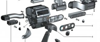
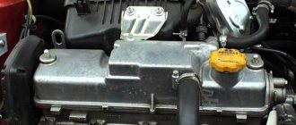
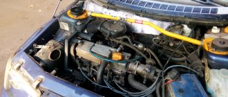
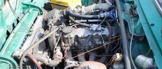
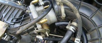
How the VTEC system works: location and types VTEC system - The Variable Valve Timing and Lift Electronic Control, an electronically controlled valve phasing system, its presence is determined by the engine model, namely the cylinder head model, oil supply solenoids and ECU engine control unit with distributed injection. The bottom image shows the location on the cylinder head where the VTEC solenoids are located, responsible for activating the long stroke rocker. The second image shows where the VTEC is located - the barrel of the solenoid indicates that the engine has VTEC. There are varieties of single-shaft SOHC VTEC system; unfortunately, the second DOHC VTEC system was not installed on D-series engines D14, D15, D16. VTEC solenoid valve resistance is 14-30 ohms, at 12 volts.
View of the solenoid of a two-stage VTEC system
Location of the solenoid on the cylinder head block of the Honda Civic
What is VTEC, how does VTEC work, the meaning of the system
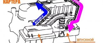
Simply put, valve timing electronically controlled, or simply VTEC. It’s enough to understand a couple of basics for what it’s needed and everything will fall into place. An ordinary 4-stroke engine draws air from the atmosphere at a pressure of 1 bar, that is, approximately 760 mmHg (This is also 1 atmosphere or 101 kPa). As the revolutions increase, the speed of the piston also increases. At low speeds, the piston sucks in air as cleanly as possible, that is, the piston slowly lowering sucks in the volume with a pressure of 1 atmosphere. As the piston speed increases, the pressure decreases, because there is no longer enough time for the air to be under normal conditions. You've probably seen dyno graphs where peak power is around 5000-6000 rpm, and then the power line drops off. This is because the engine cannot suck in any more air, it is so rarefied (that is, there are few air molecules) that it becomes difficult to spin the engine. There are many possible solutions, remove air resistance by installing a zero filter, cold intake, increasing the throttle diameter, porting the intake channels or pumping air under pressure. But Honda came up with its own way. When the critical point of engine power is reached (approximately 5500 rpm), the VTEC system on the intake valves is activated, which keeps the valves open a little longer than usual, which gives additional time to “suck in” air. now the dead center shifts to the range of 7000. Any work with an intake system such as porting gives an increase in power at the top but can take away points for traction at the bottom, since the torque also shifts to higher speeds, to which you still need to rev the engine, there is very little air a lot of. what to do? choke the engine at low end, reduce air flow by approximately reducing the diameter of the throttle valve. You've probably heard that an 8-valve engine has more low-end potential than a 16-valve engine. This is the same thing. Honda engineers came up with the ECO-VTEC system, the principle of which not only saves fuel but also “strangles” the engine up to 2500 rpm (approximately) in order to extract maximum thrust, with only 12 valves operating.
In total, it turns out that with full VTEC 3-Stage, the bottoms are strangled and have a good torque, then work in the normal 16-valve mode, and activation at high speeds is already VTEC so that more air gets in. That's all you need to know from the basics of VTEC.
VVT-i technology
VVT-i (Variable Valve Timing with intelligence) is a variable valve timing system from Toyota. It is a type of VVT and CVVT technology. Includes, as they evolve, VVT-i, VVTL-i, Dual VVT-i, VVT-iE and Valvematic technologies.
VVT-i technology was first introduced to the market in 1996 and replaced the first generation of VVT (1991, 4A-GE engine).
Depending on the operating conditions of the engine, the VVT-i system smoothly changes the valve timing. This is achieved by rotating the intake camshaft relative to the exhaust valve shaft in the range of 20-30° (according to the crankshaft rotation angle). As a result, the moment when the intake valves begin to open and the amount of “overlap” time (that is, the time when the exhaust valve is not yet closed, but the intake valve is already open) changes.
The main element of the device is the VVT-i coupling integrated into a pulley, which serves as the coupling body. The clutch rotor is located inside and is directly connected to the camshaft.
Initially, the timing of the intake valves is set in such a way as to achieve maximum torque at low crankshaft speeds. After the speed increases significantly, several cavities are made in the clutch housing, to which engine oil from the lubrication system is supplied through channels.
The increased oil pressure opens the VVT-i valve, filling one or another cavity, ensuring rotation of the rotor relative to the housing and, accordingly, displacement of the camshaft by a certain angle.
The cams have a certain shape and, when turning the crankshaft, they open the intake valves a little earlier and close later, which has a beneficial effect on increasing power and torque at high speeds.
VTEC technology
VTEC (Variable valve Timing and lift Electronic Control) is a system of dynamically variable valve timing, a proprietary development of Honda. Initially, the VTEC system was successfully implemented in engines used in sports cars, and then, after recognition and success, this system was used in engines of civilian cars.
The peculiarity of the VTEC system is that it is possible to design compact but very powerful (in terms of volume/hp) engines without the use of additional devices (turbines, compressors), while the production technology of such engines remains inexpensive, and a car with It does not experience the problems typical of turbocharged cars with the VTEC system.
The principle of operation of VTEC, in its classic form compared to other gas distribution systems, looks structurally simple - one additional cam of a larger profile was placed on the camshaft between the main cams. It turns out that there is one additional cam for each cylinder.
Two external cams are responsible for filling the combustion chamber with the fuel mixture at low and medium engine speeds, and the central one is activated at high speeds. Please note that the valves are not directly affected by the camshaft cams, but through the so-called rocker arms/rockers, of which there are also three. The outer cams act on the rockers, which ensure that the valves open independently of each other, and the central pair of cams-rocker, although they work, work, what is called idle. The valves have a minimum lift height, and the timing phases are characterized by a short duration.
As soon as the engine reaches a certain number of revolutions, i.e. goes into high speed mode, the VTEC system is activated. Under oil pressure, the synchronizing pin inside the rockers is displaced in such a way that all three rockers seem to become one whole structure, and after this the force is transmitted to the intake valves from the large camshaft cam. This increases valve stroke and valve timing.
When the number of revolutions decreases, the system returns to its original position.
The disadvantages of such a system are the stepwise transition from one mode to another and the structural complexity of implementing the blocking process.
Varieties of VTEC
Today there are several varieties of the VTEC system. The first category is designed to increase power. The second, VTEC-E, set completely different goals - fuel economy, as indicated by the prefix “E” - econom. So, the varieties:
- DOHC VTEC 1989-2001, the most powerful in the VTEC family until 2001
- SOHC VTEC 1991-2001, medium, simpler design compared to DOHC VTEC, but also less powerful
- SOHC VTEC-E 1991-2001, the most economical VTEC
- 3-stage VTEC-E 1995-2001, combined SOHC VTEC and VTEC-E, unlike them, distinguishes between low, medium and high speeds
- DOHC i-VTEC since 2001
- SOHC i-VTEC since 2006
- 3-stage i-VTEC (only on hybrids) since 2006
The peculiarity of this engine is that in the urban cycle, a car with the VTEC-E system has fuel consumption of about 6.5-7 liters of gasoline per 100 km. This is a truly outstanding result, considering that such Honda engines develop a power of 115 horsepower. But cars with such an engine lack driving sensations.
This result is achieved due to the fact that at low speeds the engine runs on a lean air-fuel mixture, which enters its cylinders only through one intake valve. This is due to the fact that on the second valve, the cam that controls the opening and closing of the valve has a ring profile and therefore only one valve actually operates.
Due to the asymmetry of the flow of the incoming combustible mixture (one valve is closed and the second is open), turbulence occurs, filling the combustion chamber better and more uniformly, which allows the engine to operate on a rather lean mixture. As the rpm increases (2500 rpm and above), the VTEC system is activated, the synchronizing rod moves under oil pressure, and the primary valve rocker engages with the secondary valve rocker and both valves operate synchronously.
i-VTEC
Honda's latest development of the variable valve timing system VTEC is a system designated i-VTEC (where the letter "i" stands for "Intellegence" - "intelligent").
The “intelligence” of this system was as follows: the phase change is controlled by a computer, using the camshaft rotation function, adjusting the advance angle. The i-VTEC system allowed Honda engines to produce more torque at low speeds, which had been a constant problem with the company's engines - while producing high power, they were characterized by little torque available at high speeds.
The i-VTEC version, if not eliminated, but significantly corrected this drawback. The i-VTEC system has begun to be installed on powerful engines of the K series and some R series, for example, in Type R series cars, or Acura RSX. Another version, on the contrary, received an “economical” direction, and began to be installed in the civilian series of engines (for example, on CR-V, Accord, Element, Odyssey, and others).
Operating principle of SOHC i-VTEC
Honda has implemented the SOHC i-VTEC on simple principles, which are that when we drive a car, we have basically two different driving styles.
We take the first driving style to be a calm ride without sudden acceleration, with an empty trunk and no passengers. In this mode, the engine speed, as a rule, does not exceed the threshold of 2.5 - 3.5 thousand revolutions per minute, and the effort on the gas pedal is minimal. Such conditions are the most favorable for fuel economy.
In the classic form, by acting on the gas pedal, we open or close the throttle valve and regulate the amount of air supplied. Depending on the amount of air entering, the electronic engine control system supplies fuel in the required proportion to form a fuel-air mixture. The harder we press the gas pedal, the more the throttle valve opens (the cross-section of the intake channel increases). At the same time, the throttle valve was an obstacle to the passage of air.
The throttle valve is an element of the intake system that regulates the flow of air into the engine.
In theory, this behavior of the throttle should help save fuel - less air comes in and, accordingly, the computer reduces the dose of fuel supplied. However, this is not quite true. In such a situation, the throttle valve acts as a resistance force, preventing the passage of air when the work process requires it. It turns out that the piston, descending below the bottom dead center in the cylinder, must suck in the fuel-air mixture, expending its own energy for this. Energy that would ultimately be transferred entirely to the wheels. This side effect is called “pump loss.”
Let's try to look at this from a practical point of view using the example of the SOHC i-VTEC system. After all, it is the elimination of pumping losses that is the advantage of the new i-VTEC on engines with a single camshaft.
All that had to be done was to leave the throttle valve open at low engine speeds and trust the i-VTEC system to regulate the supply of the fuel-air mixture. In reality, of course, not everything is so simple.
The following point should be taken into account that during the period when the throttle valve is fully open, too much air enters the intake system and, accordingly, a lot of fuel-air mixture enters the cylinders.
In standard engines, during the intake phase, the intake valves are open and the piston moves down to bottom dead center (BDC). As soon as the piston reaches bottom dead center, the intake valves close synchronously, and the piston, starting the compression phase, rises to top dead center (TDC).
But the mixture does not burn, as you probably thought. The trick of the system is that one of the two intake valves in the cylinder after the intake phase closes much later than the second.
The SOHC i-VTEC engine operates slightly differently. During the intake phase, the piston moves to BDC, the intake valves are open. During the compression phase, the piston begins to move upward to TDC. According to the condition of i-VTEC operation in economy mode, one of the intake valves remains open and under the pressure of the upward moving piston, the excess fuel-air mixture that entered the cylinder due to the fully open throttle valve is freely returned to the intake manifold.
SOHC i-VTEC mechanism
The mechanism of the SOHC i-VTEC system is similar to that of previous generations of VTEC. All engines with the SOHC i-VTEC system have two intake valves and two exhaust valves per cylinder, i.e. 16 valves per 4 cylinders. For each pair of valves there are 3 cams - two regular outer ones and one central one with a larger VTEC profile. Camshaft cams traditionally act on the valves not directly, but through rockers, of which there are also three for two valves.
When the i-VTEC system is turned off, the outer cams ensure that the valves open and each rocker operates independently of each other, and the central cam, although it rotates with the others, is idle.
Once the engine enters an operating mode that the Drive by Wire system determines is favorable for system operation, through oil pressure the system moves the rod inside the rockers so that two of the three rockers operate as a single structure. And from that point on, the intake valve rocker, which is synchronized by the stem with the VTEC cam rocker, opens the valve by an amount and duration consistent with the VTEC cam profile. Almost like a conventional variable valve timing system VTEC, with the only difference being that the systems operate under different conditions and in different phases.
Drive by Wire (DRW) or “control by wire” is an electronic digital vehicle control system.
In a conventional VTEC system, the two outer cams are responsible for operating the engine at low speeds, and the central VTEC cam is engaged at high speeds, thus providing greater opening height and period to allow as much air-fuel mixture as possible to enter the cylinders. In the “smart” SOHC i-VTEC, everything works the other way around - the operating zone of the system is in the range from 1000 to 3500 rpm. At the “tops” the motor enters the standard operating mode.
However, the RPM range is not the only factor by which the Drive by Wire system determines when the system turns on and off. Otherwise, the new i-VTEC would be little different from its predecessors.
The new SOHC i-VTEC paired with “Drive by Wire” additionally determines the load on the engine and, depending on its value, decides to turn on VTEC or not.
It is the symbol “i” in the name of the system that indicates the operation of these two systems. It turns out that the VTEC system operates at a certain engine speed and a certain amount of engine load. Therefore, “Drive by Wire”, which determines optimal conditions, is the most important component of the system as a whole.
The overall operating range of the SOHC i-VTEC is shown in the graph. The red zone on the graph is a favorable environment for the system to operate.
Working principle of VTEC
I will show you the example of the most famous and simple animation image that explains the principle of operation of VTEC. When the oil pressure in the engine is reached, as well as the speed is reached, usually 5500 RPM, the VTEC valve opens due to the solenoid, which supplies oil to the gas distribution system.
Animated demonstration of part of the VTEC system operation
Oil pressure pushes the “latches” of the rockers, which lock the main and middle rockers. Now the valves open deeper - longer. At the same moment, the fuel and ignition maps are switched in the engine control unit (ECU). Due to the richer mixture and longer opening of the valves, a more powerful impulse appears to push the piston.
Operating principle of VTEC rocker activation
VTEC Valve Opening Duration As you understand, the duration of VTEC valve opening depends on the engine RPM. At approximately 5500 rpm, VTEC turns on, at 4600 (approximately) VTEC turns off. On an automatic transmission up to 4th gear, the activation of VTEC takes no more than 5 seconds, the system is automated and, when the revolutions and speed are reached, it switches gears, which means it resets the RPM. In terms of operating time of the VTEC system, this is only a few seconds, but it is they that give the real gain. Vtek does not turn on in netralka, and in parking mode in automatic and varator.
VTEC system options
VTEC should not be considered from the standpoint of a separate system, but a whole family of engineering solutions that have been implemented over the years. There are several varieties of VTEC in the engines of full-fledged passenger cars weighing at least 1000 kg (there are also analogues for motorcycles):
- DOHC VTEC (1989-2001) - a system on Honda's most powerful naturally aspirated power unit until 2001, known as the B16A. 3 cams for the intake and exhaust valves of the cylinders were installed on each of the two camshafts. Upon reaching 5000 rpm, the gasoline engine began to work with increased power, delivering up to 180 liters with a volume of only 1.6 liters. With. All this was possible at atmospheric pressure without turbocharging. By comparison, the 1J2 diesel engine (TDI), which has powered German-made cars since the late 1990s, is turbocharged and displaces 1.9 liters but produces only 110 hp. With.
- SOHC VTEC (from 1991 to 2001) - a simplified version of VTEC. Since SOHC engines use a single camshaft for the intake and exhaust valves, VTEC is implemented only on the intake.
- SOHC VTEC-E (1991-2001) - further development of the technology, but not to increase power, but to reduce fuel consumption or engine load with a moderate driving style. By means of rockers, the cams provide a larger opening of only one of the two valves. The second one opens insignificantly, due to which a strong turbulence is formed in the area where the spark plug sparks. This makes it possible to use a lean working mixture. If the internal combustion engine switches to operating mode at higher speeds, VTEC opens both intake valves of the cylinder equally, thus adding power.
- 3-stage SOHC VTEC (1995-2001) – the third generation of SOHC VTEC. A combination of the two types of VTEC mentioned above with the ability to operate in three modes. At low speeds, only one cylinder valve opens and closes, at medium speeds - two, at high speeds a cam with a special profile is activated. As a result, both efficiency is achieved at medium and low loads, and power at high loads.
- i-VTEC (since 2001) – the most modern variation of VTEC. As before, a three-cam valve control mechanism is used. An important difference from other types of VTEC is that the timing of the opening and closing of the intake valves at the same piston position can be adjusted by an intelligent system. As a result, the degree of filling of the cylinders with the working mixture changes. At low speeds it is less, at higher speeds it is more.
VTEC 3-Stage: what is it?
Finally, I will talk about the VTEC 3-Stage system (stage 3). This system is also installed in the cylinder head; it was installed after 1996. Has 2 solenoids. It is controlled by 12 volts; when supplied, the oil supply valve opens, if there is, of course, oil pressure. It was installed on a JDM motor D15B, single-shaft SOHC, and of course not a B series. The thing is quite interesting and in demand. It has 3 stages, combines all operating modes of all types of SOHC D series. There were several types of ECUs, but only OBD2 series, below is a list of all p2j 3-Stage ECUs
- OBD2A 37820-P2J-J62 CVT
- OBD2A 37820-P2J-J63 CVT
- OBD2A 37820-P2J-J61 CVT
- OBD2A 37820-P2J-003 Mechanics
- OBD2B 37820-P2J-J11 Mechanical
- OBD2B 37820-P2J-J81 CVT from Vi-RS
- OBD2B 37820-P2J-J71 CVT
Ten excellent VTEC engines
If you are thinking about getting your first Honda for a project, or thinking about an engine for a swap, then this list will be interesting
B16A
Where installed: 1989-1993 JDM Integra XSi, RSi; 1989-1991 Civic CRX SiR
Power/Torque: 160hp/152N.m.
Why it's great: The first DOHC VTEC you can afford.
B16B Type R
Where installed: 1997-2000 JDM Civic Type R
Power/Torque: 185hp/160N.m.
Why it’s good: The B18C version with a reduced piston stroke, holds high speeds well.
B18C1
Where installed: 1994-2001 Integra GS-R
Power/Torque: 170hp/173N.m.
What's good: The first 1.8 VTEC, with a two-stage intake manifold.
B18C Type R
Where installed: 1995-2001 JDM Integra Type R
Power/Torque: 200hp/185N.m.
What's good: The most powerful of the B-series
C32B Type R
Where they installed: 2002-2005 JDM NSX-R
Power/Torque: 290hp/303N.m.
What's Good: A meticulously balanced version of the standard NSX engine. Incredibly expensive, can't be found.
F20C1
Where they installed: 2000-2005 S2000
Power/Torque: 240hp/207N.m.
Why it's good: Considered the most productive four-cylinder engine, it revs well without sacrificing average revs.
H22A1
Where installed: 1993-1996 Prelude VTEC
Power/Torque: 190hp/214N.m.
What's good: Honda's first big block. Behind him are drag records and the history of the brand.
J37A4
Where they installed: 2009-2013 TL SH-AWD
Power/Torque: 305hp/370N.m.
What's good: The most powerful Honda engine to date
K20A Type R
Where they installed: 01-05 Civic, Integra Type R
Power/Torque: 212 hp/202 N.m.
What's good: Top K-series engine, option for swappers
VTEC 3-Stage: operating principle
How VTEC 3-Stage works, the first stage starts at 0 RPM and ends at 4000 RPM. at this stage the cylinder head operates as VTEC-E. Only 12 valves work. Each cylinder has two exhaust valves but only one intake valve. This allows for economical and smooth acceleration. The next stage is the operation of all 16 valves. The first VTEC solenoid turns on. Normal mode, runs from 4000 to 6000 The last third stage, the second valve is turned on, the intake valves open for a longer period, which allows for more fuel mixture. Work from 6000 to the end point of work The entire system is turned off in the reverse order, first the 2nd solenoid, then 1 solenoid.
Time to get to work
Now that you know how VTEC works, it’s time to install it on your D14A3 or D14A4, I suggest using the translation of the DoDo Joris article that I used, or using my article on installing VTEC. However, good luck with your experiments.
How useful is the publication?
Click on a star to rate!
Average rating 5 / 5. Number of ratings: 2
No ratings yet. Be the first to rate.
Varieties of DOHC i-VTEC
DOHC i-VTEC DOHC VTEC + VTC
DOHC i-VTEC I SOHC VTEC-E + VTC + non-Vtec exhaust camshaft
| System | Type VTEC | VTC |
| DOHC i-VTEC | VTEC on intake and exhaust. VTEC response torque is 5800 rpm. | on the intake camshaft |
| DOHC i-VTEC I | VTEC-E on the intake, standard exhaust camshaft. VTEC response torque is 2500 rpm. | on the intake camshaft |
By and large, the prefix “i” in system names implies that VTC works in conjunction with the VTEC system. But before we figure out what VTC is, let’s remember the operating principle of traditional VTEC and VTEC-E, since DOHC i-VTEC in both of its manifestations is based precisely on the operating principles of the first generation VTEC.
Conclusion
Without going into the details of the design of engines with DOHC i-VTEC, we can say that the essence of the topic is revealed in this article. In fact, the new DOHC i-VTEC in both its forms is the good old VTEC supplemented with the new intelligent VTC feature. And it is precisely due to VTC that engines with DOHC i-VTEC (both subtypes) began to work much more elastically than engines with first-generation VTEC and have more traction at the bottom.
Undoubtedly, the new engines are more productive, more technologically advanced and better, but the new VTEC has lost something - due to the acquired qualities, the inclusion of VTEC, which was such a “turn on”, has become almost unnoticeable. And yet DOHC i-VTEC is impressive... “drives” and “turns”.
VTC
VTC is that additional component that turns DOHC VTEC into the new “DOHC i-VTEC” and “VTEC-E” into “DOHC i-VTEC I”. This is a mechanism that rotates the intake camshaft relative to the exhaust camshaft using oil pressure.
The abbreviation VTC stands for Variable Timing Control, which translated means “Variable Valve Timing System”. In fact, the decoding of the name has the same meaning as VTEC. In principle, the goal of these systems is the same, but each does it differently and at the same time complements each other. An additional VTC system is installed and only affects the intake camshaft.
At high speeds, the time for opening and closing the valves is much less, although more fuel-air mixture needs to be supplied. Therefore, it is necessary to increase the opening phase and valve lift height, which is what VTEC does, and the VTC system “creates favorable conditions” for the effective operation of VTEC.
If the VTEC system, with the help of an additional cam, allows you to drive the valves deeper and slightly increases the open time, then VTC makes it possible to tighten the camshaft so that the valves open earlier, which contributes to more efficient ventilation of the cylinders.
Unlike the main VTEC system, which is activated at a certain speed range, the additional VTC system operates constantly and continuously, adjusting the opening timing of the intake valves depending on the engine load. Let's figure out how she does it.