The VAZ 2110 engine with 16 valves is the most powerful and dynamic engine of the “ten”, at the same time making a car with such a power unit quite difficult to repair and maintain.
Gasoline injection engines VAZ 2110 16 cl. two, one with a working volume of 1.5 liters (VAZ-2112) and the second with a volume of 1.6 liters (VAZ-21124). The VAZ-2112 engine has one significant problem. When the timing belt breaks, the valves hit the piston. Actually, the cross-sectional image of this 16-valve engine gives a clear idea of the actual lack of sufficient clearance between the valve plates and the piston crown. That is, when the belt breaks and the piston moves to the top point by inertia, the valve can be opened and an inevitable blow occurs. Usually, when this happens, the valves bend . And in the worst case, they break, turning the combustion chamber and piston bottom into metal crumbs.
Actually, in the 1.6 liter engine (VAZ-2112) this problem no longer exists. The valves don't bend there . This was achieved by using new pistons with a special bottom shape, which has recesses in case the timing belt breaks. Let's look at photos of similar pistons below.
Below are detailed characteristics of VAZ 2110 16 valve engines.
Technical specifications
The VAZ 2110 engine has high performance. At the same time, several variants of power units from AvtoVAZ were installed on the vehicle during the production process. The “Ten” had in its arsenal several variants of a sixteen-valve engine.
Let's look at the main technical characteristics of the VAZ engines with which the 16-valve model 2110 was equipped:
VAZ 21120
| Name | Index |
| Volume | 1.5 liter (1499 cm3) |
| Number of cylinders | 4 |
| Number of valves | 16 |
| Fuel | Petrol |
| Injection system | Injector |
| Power | 93 hp |
| Fuel consumption | 7.0 l/100 km |
| Cylinder diameter | 82 mm |
Not a very popular version of the power unit. Although the engine power is high, as practice has shown, this engine did not take root on the VAZ 2110, since it had a number of design flaws. Basically, the engine was installed on a car marked VAZ 21103.
VAZ 21124
| Name | Index |
| Volume | 1.6 liter (1599 cc) |
| Number of cylinders | 4 |
| Number of valves | 16 |
| Fuel | Petrol |
| Injection system | Injector |
| Power | 89.1 hp |
| Fuel consumption | 7.0 l/100 km |
| Cylinder diameter | 82 mm |
A sixteen-valve version of the power unit, which received almost 100 horsepower and had high technical characteristics.
The average lifespan of a Lada engine is 250,000 km. If you use high-quality oil in the VAZ 2110 engine, you can increase the service life of the power unit by 20-30 thousand km.
Gas distribution system
Replacing the camshaft drive belt, in principle, differed little from the eight-valve version. The only difference was that there were two camshafts and it was necessary to combine not two, but three marks. All of them are shown in the diagram above.
Another problem with this engine was frequent valve bending. If you bothered to replace the belt, the owner had to pay, at best, for a set of valves and new pistons. Apart from completely disassembling the engine. And not only a broken belt, but weak tension and turning the pulley by several teeth could also lead to problems with the gas distribution mechanism.
The VAZ 2110, in principle, could have become one of the most modern cars if it had left the assembly line on time. An on-board computer, a simple but functional one, a decently functioning clutch, a new steering rack that appeared along with power steering - all this could have made the car even more popular if innovations had been applied in a timely manner, and not in pursuit of an already outdated model.
There are no bad cars, never have been and never will be. The Ten simply became a victim of its time, but it showed many what a modern and cheap car should be.
Service
VAZ 2110 engines are serviced quite typically. Thus, scheduled maintenance is carried out within 10-15 thousand km. If the vehicle is operated on LPG, then maintenance must be reduced to 8-10 thousand km in order to preserve the engine and extend its service life.
When servicing, it is necessary to pour only high-quality oils into the VAZ 2110 engine. Thus, there are a number of lubricating fluids that must be poured into the engine. Do not forget about using a high-quality oil filter, which will also affect the service life. The power unit maintenance scheme is quite simple, and is provided by AvtoVAZ in the repair manuals.
The VAZ 2110 engine with 16 valves is quite unpretentious in the use of oil. So, both semi-synthetic and synthetic lubricant are ideal for him. Many car enthusiasts ask the question: how much oil should be poured into the engine? Almost all engines require 3.5 liters of oil.
Schematic sketch of the VAZ-2112 engine
Detailed diagram of the VAZ-2112 engine.
1 – engine sump. 2 – front crankshaft oil seal. 3 – crankshaft. 4 – crankshaft pulley. 5 – oil pump. 6 – generator drive pulley. 7 – timing belt. 8 – front cover of the timing mechanism drive. 9 – coolant pump pulley (pump). 10 – tension roller. 11 – camshaft toothed pulley. 12 – rear cover of the timing mechanism drive. 13 – camshaft oil seal. 14 – exhaust camshaft. 15 – hydraulic pusher. 16 – valve spring. 17 – valve guide sleeve. 18 – exhaust valve. 19 – receiver. 20 – camshaft bearing cover. 21 – guide pipe. 22 – cylinder head cover. 23 – plastic cover. 24 – spark plug. 25 – intake camshaft. 26 – inlet valve. 27 – cylinder head. 28 – coupling. 29 – fuel rail. 30 – crankcase ventilation hose. 31 – nozzle. 32 – intake manifold. 33 – flywheel. 34 – crankshaft rear oil seal holder. 35 – rear crankshaft oil seal. 36 – cylinder block. 37 – oil dipstick. 38 – piston. 39 – connecting rod. 40 – connecting rod cover. 41 – crankshaft main bearing cover.
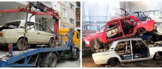
Malfunctions
A major overhaul of a VAZ 2110 engine means restoring the engine and its components to factory standards. This operation is carried out when the motor has passed its service life and there is exhaustion in the main components.
Due to the fact that the engines have been in use for a long time, some engines are 10-15 years old, a major overhaul is inevitable. So, the combustion chambers have already worn out, and the pistons have burned out from service life and mileage. In addition, engine oil for the VAZ 2110 no longer helps to maintain performance to such an extent.
So, it is worth repairing the power unit at a car service center, especially with regard to the 16-valve engine. The VAZ 2110 8-valve engine is used by most motorists in garage conditions, since it has a simple design that is similar to the Classic and Samara power units.
Tuning and modification
Recently, it has become popular to tune the VAZ 2110 engine. Many motorists turn to a tuning studio to carry out the engine modification procedure.
What can you do with the power unit? The tuning scheme is quite simple. Mechanical (boring) and electronic (chip tuning) modifications are carried out. Of course, many car owners only chip the engine to reduce consumption or increase power.
Mechanical modification of the power unit involves boring the cylinder block and installing lightweight spare parts. Thus, pistons and valves manufactured by API are installed. The best guide bushings are those from K-line Corporation. As for the guide bushings, there is no need to knock out the old ones, since you can install bronze sleeves that will lighten the weight of the motor.
After mechanical modification, you can no longer fill in ordinary lubricating fluid. Therefore, only high-quality oil for the VAZ 2110 is poured into the tuning version.
After mechanical modifications are completed, an auto electrician comes into play and adjusts the operation of the motor. This could be a regular firmware update of an old engine control unit or a chip installation. For the brains that are installed on VAZ 2110 engines, there is a soldered-in chip or an external connection.
ECU diagnostics
In modern times, many methods have become available for conducting self-diagnosis or diagnosing a power plant malfunction with your own hands. Without any problems, you can purchase various diagnostic equipment, and you don’t have to go to a car service center. So, you can connect to the ECU using a standard OBD II cable and a tablet, or purchase an ELM 327.
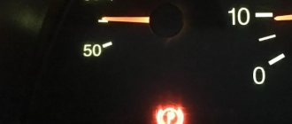
Also, some errors can be diagnosed using the instrument cluster. First you need to enable test mode:
- The ignition is turned off. Battery included.
- Press the “Reset” control button and, holding it pressed, turn on the ignition. All positions of the familiar areas (segments) should light up on the LCD—LCD control.
- Press any of the control buttons. The LCD should display the program version (Ver 1.0).
- Press any of the control buttons. The following error codes (if any) should be displayed on the positions of the first and second lines of the LCD.
- Press the “Reset” control button and hold it for no more than 3 seconds. (maybe a typo, I need more than 3c). Error codes should clear to zero.
- Press any of the control buttons. All positions of symbols (segments) should light up on the LCD - LCD control.
Error codes: 2-overvoltage of on-board network;
3-fuel level sensor error (if a break in the sensor circuit is detected within 20s);
4-error of the coolant temperature sensor (if an open circuit of the sensor is detected within 20s);
5-outside temperature sensor error (if there are no sensor readings within 20s, indication on the LCD is “-C”);
6-engine overheating (the criterion for triggering the acoustic alarm is met);
7-emergency oil pressure (the criterion for triggering the acoustic alarm is met);
8-defect of the brake system (the criterion for triggering the acoustic alarm is met);
The 9-battery is discharged (the criterion for triggering the acoustic alarm has been met);
E-determination of an error in a data packet stored in EEPROM.
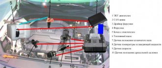
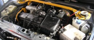
Engine device
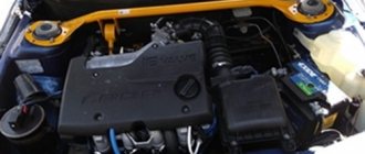
16-valve 124 engine under the hood of a “two-wheeler”
- The engine is a sixteen-valve, in-line, four-stroke gasoline engine, consisting of four cylinders. The operating order of the cylinders is: 1-3-4-2 – starting from the crankshaft pulley. With a power supply system – distributed injection, controlled via a Bosch, “January” or GM controller.
- The engine is secured in the engine compartment using four elastic supports, of which the front and rear are rods that are fixed from the engine to the body, and the left and right are identical to the VAZ-2110(11).
- On the engine, on one side there are camshaft and crankshaft drives, a coolant pump (about checking the pump and choosing a pump - note), a generator, as well as a timing belt (about replacing it here), on the other side there are sensors: coolant temperature, pressure oil, starter, thermostat, front: ramp with injectors, intake manifold, oil dipstick, knock sensor, crankcase ventilation hose, phase sensor. On the reverse side: oil filter, crankshaft position sensor, exhaust manifold. Top: spark plugs, high-voltage wires. More details about all sensors are written here.
- The cast-iron cylinder block has the same index “21083” with engines from the VAZ-2110 (11), however, they have different screws for the cylinder heads M10x1.25 in contrast to M12x1.25, as well as their smallest entry depth.
- Each engine has its own serial number.
Cylinders
This is what the cylinder block looks like with the engine removed.
The engine cylinders are bored directly into the block. The initial diameter is 82 mm and during repairs can be increased by 0.4 or 0.8 mm. The class of the cylinder is marked on the bottom plane of the block in Latin letters.
Crankshaft
This element practically does not fail.
The crankshaft is made of high-strength cast iron, and is equipped with five main journals, four connecting rod journals, and eight counterweights cast together with the shaft. The difference between this crankshaft and its analogues with the VAZ-2112 is due to its increased strength and wear resistance, so installation from younger models is completely excluded. The flywheel is secured to the back of the crankshaft using six self-locking bolts.
Pistons
These pistons apparently already have grooves for the valves. They won't be driven down anymore.
The piston in the engine is made of aluminum alloy, the piston skirt is conical in the longitudinal section, and oval in the transverse section. A distinctive feature of the pistons for the VAZ-2112 is that they have four recesses for the valves to avoid bending and subsequent replacement of the valves, whereas on younger models they are flat. For one engine, pistons should be selected based on weight, not allowing a difference of more than 5 grams, to reduce the imbalance of the crank mechanism (approx.). There are three rings mounted on the piston: the upper ones are compression rings that prevent gases from breaking through into the engine crankcase; they also help remove heat from the piston to the cylinder. The lower ring is an oil scraper ring (about replacing it here).
Connecting rods
As a rule, they are changed along with the pistons.
The connecting rods are made of steel and are divided into weight classes - they are marked with paint or a letter on the cover. On the covers, as well as on the connecting rods, the cylinder number is stamped (it should be on one side of the connecting rod and the cover).
Piston pins
This is what a piston pin looks like.
The piston pin is steel, tubular in section. It is secured from falling out by two retaining spring rings, which are located in the grooves of the piston bosses. Based on their diameter, they can be divided into three different classes: 1 – 21.978-21.982 ; 2 – 21.982-21.986 ; 3 – 21,986-21,990 . The piston class is also stamped on its bottom. The piston and pin must be of the same class.
View of the cylinder head on a dismantled engine.
Cylinder head - made of aluminum alloy, common to all four cylinders, centered on the block with two bushings and secured with ten screws. On the top of the cylinder head there are camshaft supports, five on each side.
Camshafts
Camshafts and their pulleys
The camshafts are cast, cast iron, five-bearing, each with eight cams. The camshafts are driven by a toothed belt from the crankshaft. Due to increased loads on the timing belt, its width in the VAZ-2112 engine, compared to analogues 2110(11), has been increased from 19.0 to 25.4 mm (accordingly, the width of the toothed pulleys and rollers has been increased). Therefore, the timing belt tension has also changed. There is a support roller under the intake camshaft pulley, and a tension roller under the exhaust camshaft.
Valves
These valves are not afraid of bending if there are grooves on the pistons.
The valves are made of steel, while the outlet is made of heat-resistant steel with a directional chamfer, and the inlet area is larger than the outlet. If we compare in size, they are smaller than the analogues of the “tenth” model. They are arranged in two rows in a V-shape. They are driven by cams using hydraulic pushers, which in turn are very sensitive to the purity of the oil and its quality. And in the presence of mechanical impurities, premature failure of these elements is possible, which will be accompanied by increased noise during the operation of hydraulic pushers. How to replace these elements is described in detail in this article.
Error codes
Error codes from the engine's electronic control unit can often identify faults in electrical circuits and basic systems. Diagnostics are usually carried out to identify faulty sensors.
Decoding the error code: 0102 Low signal level of the mass air flow sensor 0103 High level of the mass air flow sensor 0112 Low level of the intake air temperature sensor 0113 High level of the intake air temperature sensor 0115 Incorrect signal of the coolant temperature sensor 0116 Incorrect signal of the coolant temperature sensor 0117 Low coolant temperature sensor signal level 0118 Coolant temperature sensor signal high 0122 Throttle position sensor signal low 0123 Throttle position sensor signal high 0130 Oxygen sensor 1 signal incorrect 0131 Oxygen sensor 1 signal low 0132 Crankshaft sensor signal high 1 0133 Oxygen sensor 1 response slow 0134 Oxygen sensor 1 signal missing 0135 Oxygen sensor 1 heater fault 0136 Oxygen sensor 2 short to ground 0137 Oxygen sensor 2 signal low 0138 Oxygen sensor 2 signal high 0140 Oxygen sensor 2 open 0141 Oxygen sensor heater fault 2 0171 Mixture too lean 0172 Mixture too rich 0201 Injector control circuit open 1 0202 Injector control circuit open 2 0203 Injector control circuit open 3 0204 Injector control circuit 4 open 0261 Injector circuit short to ground 1 0264 Injector circuit short to ground 2 026 7 Short circuit to ground of injector circuit 3 0270 Short to ground of injector 4 circuit 0262 Short to +12V of injector 1 circuit 0265 Short to +12V of injector 2 circuit 0268 Short to +12V of injector 3 circuit 0271 Short to +12V of injector 4 circuit 0300 Many misfires 03 01 Misfire in cylinder 1 0302 Misfire in cylinder 2 0303 Misfire in cylinder 3 0304 Misfire in cylinder 4 0325 Open circuit of knock sensor 0327 Low signal level of knock sensor 0328 High level of knock sensor signal 0335 Incorrect signal from crankshaft position sensor 0336 Error in position sensor signal crankshaft 0340 Phase sensor error 0342 Low phase sensor signal 0343 High phase sensor signal 0422 Low converter efficiency 0443 Malfunction of the canister purge valve circuit 0444 Short or open circuit of the canister purge valve 0445 Short to ground of the canister purge valve 0480 Malfunction of the fan circuit a cooling 1 0500 Incorrect sensor signal speed 0501 Incorrect speed sensor signal 0503 Interruption of speed sensor signal 0505 Idle speed controller error 0506 Low idle speed 0507 High idle speed 0560 Incorrect on-board network voltage 0562 Low on-board network voltage 0563 High on-board network voltage 0601 ROM error 0603 Error External RAM 0604 Error Internal RAM 0607 Knock channel malfunction 1102 Oxygen sensor heater resistance low 1115 Oxygen sensor heater circuit faulty 1123 Idle rich 1124 Idle lean 1127 Part Load rich 1128 Part Load lean 1135 Sensor heater circuit oxygen 1 break, short circuit 1136 A rich mixture in small load 1137 Poor mixture in small load mode 1140 The measured load differs from calculating +12V 1425 Control circuit of the canister purge valve short circuit to ground 1426 Control circuit of the canister purge valve open 1500 Open circuit of the fuel pump relay control circuit 1501 Short circuit to ground of the fuel pump relay control circuit 1502 Short circuit to +12V of the fuel pump relay control circuit 1509 Overload of the idle speed regulator control circuit a 1513 Idle air control circuit short circuit to ground 1514 Idle air control circuit short circuit to +12V, open 1541 Fuel pump relay control circuit open 1570 Incorrect APS signal 1600 No connection with APS 1602 Loss of on-board power supply voltage to the ECU 1603 EEPROM error 1606 Yes rough road mark incorrect signal 1616 Rough road sensor low signal 1612 ECU reset error 1617 Rough road sensor high signal 1620 RFOM error 1621 RAM error 1622 EPROM error 1640 EEPROM Test error 1689 Incorrect error codes 0337 Crankshaft position sensor, short to ground 0338 Crankshaft position sensor, open circuit 0441 Air flow through the valve is incorrect 0481 Cooling fan circuit malfunction 2 0615 Starter relay circuit open 0616 Starter relay circuit short circuit to ground 0617 Starter relay circuit short circuit to +12V 1141 Oxygen sensor 1 heater malfunction after the neutralizer 230 Fuel pump relay circuit malfunction 26 3 Driver failure Injector 1 266 Injector Driver 2 Malfunction 269 Injector Driver 3 Malfunction 272 Injector Driver 4 Malfunction 650 CheckEngine Lamp Circuit Malfunction
Design Features
Since AvtoVAZ management involved specialists from General Motors (timing) and Porsche (layout) in the design of the 16-valve internal combustion engine, the 2112 engine has the following design solutions:
- the intake valves are controlled by the cams of their own camshaft, the exhaust valves have a separate camshaft;
- oil channels are laid inside the cylinder head;
- floating piston pin fit;
- holes in the block for additional attachments;
- forged steel connecting rods 121 mm long.
Overhaul 2112
A pleasant feature for the owners of these engines are hydraulic pushers, which eliminate the need for periodic valve adjustments with your own hands or at a service station.
Operating principle of hydraulic pushers
Maintenance
The ergonomic design of the internal combustion engine allows you to service the 2112 engine with the following frequency:
| Maintenance object | Time, year or mileage, 10,000 km (whichever comes first) |
| Timing belt | replacement after 100,000 km |
| Battery | 1/20000 km |
| Valve clearance | 2 /20000 km |
| Crankcase ventilation | 2 /20000 km |
| Belts that drive attachments | 2 /20000 km |
| Fuel line and tank cap | 2 /40000 km |
| Motor oil | 1/10000 km |
| Oil filter | 1/10000 km |
| Air filter | 1 – 2/40000 km |
| Fuel filter | 4 /20000 km |
| Heating/Cooling Fittings and Hoses | 2 /40000 |
| Coolant | 2 /20000 km |
| Oxygen sensor | 1.5/100000 km |
| Spark plug | 1 – 2 /20000 km |
| Exhaust manifold | 2/40000 km |
Unlike coolant, oil partially settles on the walls of the lubrication channels, so with a volume of 3.5 liters, 3.2 liters of a semi-synthetic product is actually required.