An electric starter is an extremely important element of any modern car, ensuring its mechanized starting. If it fails, then it will simply be impossible to start the car except “from the pusher”. In today’s article we will look at how the starter circuit of the VAZ 2114 injector works, on what principle it works, and also what to do if this device fails.
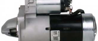
Starter VAZ 2114
Connection diagram for the VAZ 2114 (2113, 2115) car starter
Several models of starters are installed on VAZ 2114, 2113, 2115 cars.
They differ slightly in their design. But their connection method is the same.
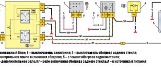
Here is a wiring diagram for starter 5712.3708 with a description of the features and procedure for turning it on and off.
Connection diagram for the VAZ 2114 (2113, 2115) car starter
Description of the scheme
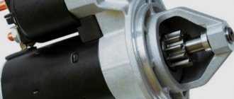
— Starter 5712.3708 of VAZ 2114, 2113, 2115 cars is a four-pole, four-brush DC electric motor with excitation from permanent magnets, with a planetary gearbox, a freewheel roller clutch and a two-winding traction relay.
— The starter is turned on by turning the key in the ignition switch to position II (starter). In this case, voltage is supplied from the positive terminal of the battery, through the “B+” terminal of the generator and the ignition switch contacts to terminal “50” of the starter solenoid (traction) relay. The relay armature is pulled into the interior of the pull-in relay (the pull-in winding of the relay is activated), and the bendix associated with it moves forward. Its gear meshes with the teeth of the flywheel. The contacts inside the relay close and electric current from the battery is supplied to the starter motor, turning it along with the gear and flywheel. The engine starts.
After closing the contacts of the traction relay, its retractor winding is turned off. The operating voltage of the traction relay is no more than 8 V at a temperature of plus 20 degrees.
— Blocking the restart of the starter when the engine is running on VAZ 2114, 2115, 2113 vehicles is implemented due to the design of the ignition switch. It is designed so that after turning the key to position II (starter) and subsequent return to position I (parking), it can only be turned back to position II (starter) if the ignition is completely turned off (position O - parking).
Notes and additions
— Technical characteristics of starter 5712.3701 for VAZ 2114 (2115, 2113)
Rated power - 1.55 kW
Current consumption at maximum power - no more than 375 A
Current consumption in the inhibited state - no more than 700 A
Current consumption in idle mode - no more than 80 A
Source
The starter does not turn over, what should I do?
In the life of owners of the VAZ-2114, and other cars close to this line (see above), sometimes such an unpleasant moment arises when you need to go somewhere, but it is not possible to start the power plant due to the fact that the starter does not turn the flywheel engine.
That is, when you turn the ignition key to the “start” position, nothing happens.
And if in the summer you can calmly look for the cause of the malfunction, then in the winter, in severe frost, you won’t spend much time searching for the malfunction. And in order to quickly fix a breakdown, you need to know where to look for it.
How to quickly start your car in cold weather, see below.
VAZ starter connection diagram
VAZ cars use starters, which are a DC electric motor with an electromagnetic two-winding traction relay and a roller freewheel clutch (overrunning clutch). Starters are used to provide the minimum crankshaft speed required to start the engine. The starter is powered in starting mode from the battery.
The starter relay is connected to the power circuit, thereby closing and opening the circuit, depending on how fast the crankshaft rotates. The starter design on all cars is the same, with only minor design differences. If you understand how the starter works in one car, you can easily figure it out in another.
To prevent a starter failure from taking you by surprise, let’s look at how to replace it yourself. But first, read the theory and study all the options for starter connection diagrams for different models of VAZ cars, collected by the editors of 2 Schemes.ru from familiar auto electricians.
VAZ 2101 starter connection diagram
- starter;
- holding winding of traction relay;
- ignition switch;
- generator VAZ 2101;
- fuse box;
- pull-in winding of the traction relay;
- accumulator battery.
Under normal loads, the current generated by the starter is 150 A. When heavy loads occur, for example in winter, the resulting current can reach 500 A. This is a serious test for this electrical unit, so it is not recommended to keep the key on the start for more than 10 seconds, and repeated starting attempts must be made with a break of at least a minute.
VAZ-2115 wiring harness diagrams
With a 9-pin square block for the injector, a non-locking button for turning on the automatic transmission, and a starter blocking relay (the injector turns off the starter if the engine is running).
Instrument panel harness
There is a relay for rear fog lights (attached next to the mounting block, the fuse dangles nearby), a button without locking. It works like this: if the low beam and/or front fog lights (if equipped) are on, press and release the button - the automatic transmissions turn on. They turn off when the button is pressed again or automatically when the headlights are turned off, so that the driver does not forget to turn them off.
VAZ 2106 starter connection diagram
- starter;
- generator;
- accumulator battery;
- pull-in winding of the traction relay;
- ignition switch;
- traction relay holding coil
| 1 – drive side cover; | 14 – relay cover; |
| 2 – retaining ring; | 15 – contact bolts; |
| 3 – restrictive ring; | 16 – collector; |
| 4 – drive gear; | 17 – brush; |
| 5 – overrunning clutch; | 18 – armature shaft bushing; |
| 6 – drive ring; | 19 – cover from the collector side; |
| 7 – rubber plug; | 20 – casing; |
| 8 – drive lever; | 21 – shunt coil of the stator winding; |
| 9 – relay anchor 2106; | 22 – body; |
| 10 – holding winding of the traction relay; | 23 – stator pole fastening screw; |
| 11 – pull-in winding of the traction relay; | 24 – anchor; |
| 12 – relay coupling bolt; | 25 – armature winding; |
| 13 – contact plate; | 26 – intermediate ring. |
Starter diagram VAZ 2108, 2109, 21099
Electric current enters the starter circuit from terminal “30” of the generator. Next, through block Ш8 (Х8) of the mounting block (pins 5,6), block Ш1 (Х1) - pink wire, to the ignition switch. The driver turns the key in the ignition to turn on the starter (position 2) and closes the contacts (50, 30). After which the ignition switch, through the red wire, current flows to block Ш1 (X1) of the mounting block (pin 8), then block Ш5 (Х5) (pin 4), starter switch relay (pin 85). The relay is activated. From terminal “30” of the start relay, current flows to terminal “50” of the starter traction relay, energizing its winding. The traction relay is activated, activating the starter.
The starter electrical circuit uses a switching relay 111.3747-10.
- Screw securing the protective cap.
- Protective cap.
- Retaining half ring.
- Rear cover fastening nut.
- Back cover.
- Brush springs.
- Brush guides (outer part).
- Brushes.
- Stator.
- Anchor.
- Drive lever.
- Drive unit.
- Restriction ring.
- Retaining ring.
- Drive lever axis.
- Screws for securing the traction relay.
- Front cover.
- Plastic sealing ring for the lid.
- Tie rods.
- Rubber plug.
- Traction relay core.
- Return spring.
- O-ring for traction relay.
- Traction relay.
- Sealing washer.
- Adjusting washers.
Causes and troubleshooting
Let's look at the reasons why the starter on a VAZ-2114 does not turn.
The causes of the malfunction may lie not only in it, but also in other elements involved in the circuit.
Moreover, the behavior of the circuit itself when closed can tell you where to look for a breakdown.
The key is in the “start” position and the starter does not start.
If, after turning the key to the “start” position, the starter does not spin, but the solenoid relays are activated (a distinct click is heard, indicating that the armature has moved), and the lamps on the dashboard have noticeably dimmed, then the reason may be:
- In a discharged battery
. Electric consumers left turned on at night drain the battery and the amount of its energy is not enough to power the electric motor. Severe frosts can also affect the battery (exposure to sub-zero temperatures leads to an increase in resistance in the battery). To start a car you need to either charge the battery or “light” it from another car; - In severe oxidation of contacts
. Or insufficient contact at the battery terminals and the solenoid relay terminals, including ground. This causes an increase in resistance at the connection points, so the energy from the battery will not be enough to turn the electric motor. In order for the starter to start turning, it is necessary to check all the connections between the battery and the starter, clean and tighten them if necessary. To prevent oxidation, it is necessary to lubricate the battery terminals; - In the burning of contacts inside the retractor relay (nickels)
. For this reason, when the circuit is closed by an armature, strong voltage losses occur at the contact points. To fix the problem, you will have to remove the starter, disassemble the solenoid relay to clean the nickels, or simply replace it; - In severe wear of the contact brushes of the electric motor
. Due to this malfunction, the contact between the brush block and the rotor is broken and the electric motor will not rotate. This can all be “cured” by replacing the brushes; - In a short circuit of the motor windings
. The only way to restore functionality is to rewind the windings or replace the burnt-out starter with a new one.
When you turn the key, all warning lights come on.
If, when you turn the key, all the warning lights are on, but even the relay does not work, this may indicate:
- Blown fuse of the power circuit leading to the ignition switch or insufficient contact at the connection points. In this case, the voltage from the battery will not flow to the lock, and, accordingly, to the coil of the solenoid relay. Therefore, first of all, you should check the condition of the fuse and, if necessary, replace it, and also check all connection points;
- Burning of the ignition switch contact group. For this reason, the circuit will not close and the relay will not work. You can check this quite simply - you need to use a screwdriver to connect the terminals on the solenoid relay (in essence, apply voltage to the electric motor, bypassing the relay). If at the same time the starter starts to turn, then the reason is in the lock. Additionally, you can check by disconnecting the wires from the lock and short-circuiting those that lead to the relay (but for this you need to know where which wire is). If the short circuit causes the starter to turn on, then the fault definitely lies in the lock and can be eliminated by replacing the burnt element with a new one;
- Closing the coil of the solenoid relay. As a result, the latter ceases to perform its functions. You can check this by closing the contacts on it with a screwdriver. If it is determined that the relay does not work, then the latter is replaced.
- Anchor jamming. The magnetic field cannot draw it in and the circuit does not close. The test is done as usual - by shorting the terminals. Everything can be eliminated by disassembling the relay and cleaning it.
These are the main reasons why the starter does not turn. If you sequentially check all the elements of the circuit, the fault can be identified very quickly.
Important to read: Do-it-yourself starter repair.
Starter circuit for VAZ 2110, 2111, 2112
Starters of type 57.3708 were installed on VAZ-2110 cars and had the following technical characteristics:
- Rated power 1.55 kW
- Current consumption at maximum power no more than 375 Amperes
- Current consumption in the inhibited state is no more than 700 Amperes
- Current consumption in idle mode no more than 80 Amperes
The connection diagram for the starter for the ten is shown above, here is its explanation:
- battery
- generator
- the starter itself
- egnition lock
| 1 – drive shaft; | 20 – contact bolts; |
| 2 – front cover bushing; | 21 – output of “positive” brushes; |
| 3 – restrictive ring; | 22 – bracket; |
| 4 – gear with the inner ring of the overrunning clutch; | 23 – brush holder; |
| 5 – overrunning clutch roller; | 24 – “positive” brush; |
| 6 – drive shaft support with liner; | 25 – armature shaft; |
| 7 – planetary gear axis; | 26 – tie rod; |
| 8 – gasket; | 27 – back cover with bushing; |
| 9 – lever bracket; | 28 – collector; |
| 10 – drive lever; | 29 – body; |
| 11 – front cover; | 30 – permanent magnet; |
| 12 – relay anchor; | 31 – armature core; |
| 13 – holding winding; | 32 – armature shaft support with liner; |
| 14 – retractor winding; | 33 – planetary gear; |
| 15 – traction relay; | 34 – central (drive) gear; |
| 16 – traction relay rod; | 35 – carrier; |
| 17 – traction relay core; | 36 – gear with internal teeth; |
| 18 – contact plate; | 37 – layering ring; |
| 19 – traction relay cover; | 38 – hub with the outer ring of the overrunning clutch. |
Starter solenoid relay
The starter relay is called a pull-in relay. This is due to the principle of its operation - it performs the function of connecting the starting device to the electrical circuit and connecting its armature to the crankshaft. It happens like this: when no current is supplied to the windings of the device, its armature, under the action of the return spring, remains in the forward position. The same spring, through a special fork, holds the Bendix gear, preventing it from engaging with the crankshaft flywheel ring.
By turning the key in the ignition, we supply current to the winding of the device. Under the influence of an electromagnetic field, the armature is fed back (pulled into the housing), closing the starter power contacts. The Bendix gear also moves, engaging with the flywheel. At the same moment, the retracting winding is turned off, and the holding winding comes into play. The force from the starter shaft is transmitted through the gear to the flywheel, causing the crankshaft to rotate until we no longer hold the ignition key in the start position.
What functions does the solenoid relay perform:
- Protects the starter from shorting contacts in the ignition.
- In order to turn off the power to the starter in a situation where the engine is running and the key shows the “starter” mode.
- Provides relief of contacts in the ignition switch.
When the engine starts, voltage from the generator goes to the relay coil. Then the gears of the drive system begin to work, due to which a magnetic field is created. The flywheel of the propulsion system is working. The gear begins its work thanks to the holding winding, while the bolts are closed. When the key is returned to the ignition switch, the winding is de-energized, thus disconnecting the gear and flywheel. This scheme applies to modern cars, including VAZ models.
If the starter makes a loud noise, the pole or starter could be loose. In the first situation, strengthen the fastening by tightening the screw, and in the second, secure the starter. If you disassemble the starter and see that the clutch is starting to slip, then the only thing you need to do is replace the starter drive.
Signs of a faulty starter
You can find out that the car starter has failed by the following number of indirect signs:
- when you turn the key, the starter does not work - the battery is completely discharged, the power circuit is broken, or one of the main windings is burned out;
- after starting, the starter spins, but does not rotate the flywheel - the solenoid relay is broken or the bendix has failed;
- during startup, the starter rotates slowly, sometimes it can stop spontaneously - either one of the windings is shorted or contact with ground is lost;
- When you try to start, you hear a crunching and grinding sound - the teeth of the Bendix or the crankshaft flywheel itself are worn out or broken.
VAZ 2114 starter failure
As you can see, not in all cases the starter itself is to blame for starter malfunctions, especially considering the fact that it is an extremely reliable device. That is why, if it is not working correctly, you should first examine its electrical circuit ( the VAZ 2114 starter wiring diagram was given above), check the condition of the battery and the presence of contact between the device and ground, and only then dismantle the starter itself
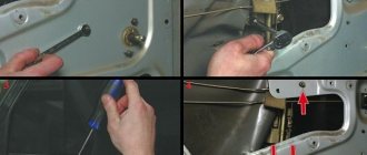
Connecting wires to the starter
Connecting a starter to a VAZ - instructions. Attach the relay in a convenient place (for example, a washer reservoir). Connect the wires to the starter. Then remove the red wire located on the flat terminal of the relay, and you need to make a connection with the connector of the male wire and the wire from the new relay.
Place the wire with a ring terminal for 8 mm on the positive side of the starter and tighten it with a nut. Place the wire of the new “female” type relay onto the contact that was released at the traction relay. This wire will transmit the positive to the coil. Using a clamp, tighten the new wire and the stock one together. Screw a small length of wire from the coil. Now you can turn on the new relay.
Source
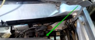
Where is the starter relay located on the VAZ 2114?
Two relays are connected to the starter:
- The retractor relay is located above the starter, acting as its mechanism. Its position is shown in the first figure with a general view of the unit and in the diagram of the mechanism itself.
- The next relay is a unit located to the side and is connected by a contact electrical wire to the solenoid relay. This electrical device often breaks down and needs to be replaced, so the car owner needs to know its location in a complex system of components and parts.
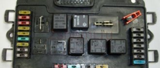
Unlike many cars, including VAZ ones, the starter relay on the VAZ 2114 is located in the engine compartment.
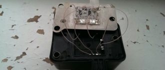
And it is a small box like this:
VAZ 2114 diagram
Detailed color diagrams of the VAZ 2114 wiring (carburetor, injector) are provided with a description of the electrical equipment for various modifications. The information is intended for self-repair of cars. Many electrical circuits are divided into several sections for ease of viewing via a computer or smartphone; there are also circuits in the form of one picture with a description of the elements - for printing on a printer.
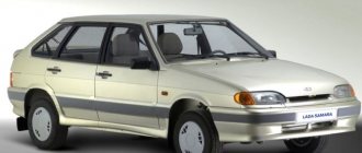
The VAZ 2114 (Samara-2) car is built on the VAZ 21093 platform and is an improved version of it. The first prototype of the hatchback was assembled back in 2000. A year later, the Volzhsky Automobile Plant produced the first pilot batch of 50 VAZ-2114 cars, and in the same 2001 the hatchback was first introduced to the market. The interior features a new instrument panel, a new steering wheel, an adjustable steering column, power windows and a new heater. Years of production 2114: 2001—2013
The fourteenth model was previously equipped with a 1.5 liter eight-valve engine, borrowed from the VAZ 2111 model with an injector. A little later it was replaced by the VAZ 11183-1000 version, which complies with the Euro-3 standard. The VAZ 2114 injector received a more powerful engine, and this is one of the reasons that the wiring of the 2114 has also changed.
A wiring harness has been added for connecting to the electronic switch. A harness has also appeared for connecting to the ignition module terminal.
Replacing high-voltage wires will require additional attention, because the connection procedure depends on the year of manufacture of the car. Until 2004, 4-pin ignition modules were installed, and after that - 3-pin. Connecting the adsorber valve to the injection system controller also provided another additional element. An adsorber is an electromechanical device used for ventilation and removal of condensate in a gas tank. Complications also affected the interior part. The dashboard received improvements in the form of the appearance of a BC (on-board computer), a new instrument panel and a change in the position of the glove compartment.
Other malfunctions
There are other types of breakdowns that can occur with the starting system of the VAZ-2114 power plant, and each of them has its own symptoms:
- If the starter turns even after it has been switched off, the most common culprit is that the relay armature is stuck in the retracted position. In this case, you can stop the starter only by disconnecting the battery from the on-board network (by removing one of the terminals). Everything can be eliminated by rebuilding the relay or replacing it;
- If the starter turns on without permission, it is likely that the relay cover is damaged. As a result, the armature spring, which holds it in the depressed position, loses its support and the armature itself can move without permission inside the relay, periodically closing the contacts. By replacing the retractor, this malfunction can be eliminated;
- The starter starts working, but the flywheel does not spin, and a cracking sound is heard. There are two reasons for this malfunction. The first is that the starter mounting bolts have become loose, so the starter has come loose and is warped. As a result, the gear cannot engage, but at the same time it rotates and contacts the flywheel (hence the rattling noise). The second is that the gear teeth have crumbled or worn out, resulting in no engagement. To eliminate this, you should first check the tightness of the bolts; if it is normal, then you need to remove the assembly and inspect the condition of the gear;
- The starter turns on, but the flywheel does not turn, and there are no external sounds. This indicates that the gear is not reaching the flywheel. To understand why this happened, you will also have to remove the starter and carry out an inspection.
Read on the topic: How to check a car starter, useful tips.
As you can see, most often problems arise not with the electric motor itself, but with its additional elements - the relay and bendix.
Malfunctions can also occur due to other elements included in the circuit - a lock, fuses, as well as the condition of the wiring connections. Watch the video why the starter on a VAZ 2114 does not turn.
Car modifications 2114
VAZ-21140 . Modification with an 8-valve injection engine VAZ-2111, 1.5 liters and 77 horsepower. Serial production from 2003 to 2007
VAZ-21144 . Modification with an 8-valve VAZ-21114 engine, 1.6 liters and 81.6 horsepower. Years of serial production: 2007-2013.
VAZ-211440 . Another modification released in 2007, it was equipped with a VAZ-11183 engine with a volume of 1.6 liters and a power of 82 horsepower. The car was discontinued in 2013.
VAZ-211440-24 . Released in 2009, a modification with an injection 16-valve VAZ-21124 engine with a volume of 1.6 liters and a power of 89.1 horsepower. Discontinued in 2013.
VAZ-211440-26 . Modification with a 16-valve injection engine VAZ-21126, which complies with the Euro-3 environmental standard, with a volume of 1.6 liters and a power of 98 hp. The car was produced from 2010 to 2013.
Wiring diagram VAZ-2114 for old models
Electrical diagram of car 2114: 1 - headlight; 2 [Installed on a part of the car] - fog lamp; 3 — ambient air temperature sensor; 4 — electric engine radiator fan; 5 — block for connection to the wiring harness of the engine control system; 6 — engine compartment lamp switch; 7 [Installed on a part of the car] - reserve block for connecting an audio signal with one terminal (the negative terminal is connected to the body); 8 — sound signal; 9 — liquid level sensor in the windshield washer reservoir; 10 [Installed on a part of the car] - brake pad wear sensor; 11 — low oil level sensor; 12 - generator; 13 [Installed on a part of the car] - engine compartment lamp; 14 — temperature indicator sensor; 15 — starter; 16 — battery; 17 [Installed on a part of the car] - relay for turning on fog lights; 18 — coolant level sensor in the expansion tank; 19 — sensor of insufficient brake fluid level; 20 — reversing light switch; 21 — windshield wiper gear motor; 22 — emergency oil pressure sensor; 23 — rear window washer electric pump; 24 — electric pump for windshield washer; 25 — instrument panel; 26 — mounting block of fuses and relays; 27 — brake signal switch; 28 — ignition relay; 29 - ignition switch (lock); 30 — glove box lighting lamp; 31 — switch for the glove compartment lighting lamp; 32 — rear window heating switch; 33 — rear fog light switch; 34 [Installed on a part of the car] - fog light switch; 35 - combined switch for side lights and headlights; 36 — alarm switch; 37 — steering column switches; 38 — brightness control for instrument lighting; 39 — illumination lamp for the headlight hydraulic adjustment control handle; 40 — socket for connecting a portable lamp; 41 — side direction indicator; 42 — interior lighting switch (front door open sensor); 43 — interior lamp; 44 — electric fan of the ventilation and heating system; 45 — additional resistor of the electric fan of the ventilation and heating system; 46 — switch for operating modes of the electric fan of the ventilation and heating system; 47 — illumination lamp for the handle of the operating mode switch of the electric fan of the ventilation and heating system; 48 — backlight lamp for the heater control unit; 49 — display unit of the on-board control system; 50 [Installed on part of the car] - trip computer; 51 — interior lighting switch (rear door open sensor); 52 [Installed on a part of the car] - block for connecting a clock; 53 — fuel module; 54 — ashtray illumination lamp; 55 — cigarette lighter; 56 — interior lamp; 57 — switch for the parking brake warning lamp; 58 — rear light; 59 — license plate light; 60 — additional brake light; 61 — heating element for heating the rear window; 62 — rear window wiper gear motor; A - numbers of pins in connecting blocks.
VAZ-2114 diagram (second option)
Electrical diagram of VAZ-2114 cars (without engine control system):
1 — block headlights; 2 — fog lights; 3 — air temperature sensor; 4 — electric motor of the engine cooling system fan; 5 — blocks connected to the wiring harness of the ignition system; 6 — engine compartment lamp switch; 7 — block for connecting to a single-wire type audio signal; 8 — sound signal; 9 — washer fluid level sensor; 10 — front brake pad wear sensor; 11 — oil level sensor; 12 - generator; 13 — engine compartment lamp; 14 — coolant temperature indicator sensor; 15 — starter; 16 - battery; 17 — relay for turning on fog lights; 18 — coolant level sensor; 19 — brake fluid level sensor; 20 — reverse light switch; 21 — windshield wiper gearmotor; 22 — oil pressure warning lamp sensor; 23 — block for connecting to the rear window washer electric motor; 24 — electric motor for windshield washer; 25 — instrument cluster; 26 — mounting block 2114; 27 — brake light switch; 28 — ignition relay; 29 — ignition switch; 30 — glove box lighting lamp; 31 — glove box lighting switch; 32 — rear window heating element switch; 33 — rear fog light switch; 34 — fog lamp switch; 35 — switch for external lighting lamps; 36 — alarm switch; 37 — steering column switches; 38 — switch for instrument lighting lamps; 39 — lamp for illuminating the headlight hydrocorrector scale; 40 — plug socket for a portable lamp; 41 — side direction indicators; 42 — lamp switch on the front door pillars; 43 — lamp for individual interior lighting; 44 — heater fan electric motor; 45 — additional resistor of the heater electric motor; 46 — heater fan switch; 47 — heater switch illumination lamp; 48 — lamp for illuminating the heater levers; 49 — on-board control system unit; 50 — trip computer; 51 — lamp switch on the rear door pillars; 52 — block for connecting the wiring harness of the engine control system; 53 — electric fuel pump and gasoline quantity sensor; 54 — front ashtray illumination lamp; 55 — cigarette lighter 2114; 56 — trunk lighting lamp; 57 — trunk light switch; 58 — interior lamp; 59 — parking brake warning lamp switch; 60 — rear external lights; 61 — rear internal lights; 62 — block for connection to the rear window heating element; 63 — license plate lights; 64 - additional brake signal located in the spoiler.
Conventional numbering of plugs in blocks:
- A — headlight blocks;
- B — electric fuel pump block;
- C — blocks of the mounting block, ignition switch, windshield wiper gearmotor;
- D — blocks for the interior lamp.
Electrical diagram of VAZ-2115-01
Years of production 2115: 1997—2012. This is a circuit with a regular button for rear fog lights (with locking), a fluorescent interior light, a connector for the clock and an 8-pin connector for the injector wiring.
1 — block headlights; 2 — fog lights; 3 — air temperature sensor; 4 - generator; 5 — electric motor of the engine cooling system fan; 6 — fan motor activation sensor; 7 — engine compartment lamp switch; 8 — block for connection to a single-wire type audio signal; 9 — sound signal; 10 — oil level sensor; 11 — front brake pad wear sensors; 12 — washer fluid level sensor; 13 — spark plugs; 14 — ignition distributor sensor; 15 - switch; 16 — carburetor solenoid valve control unit; 17 — carburetor solenoid valve; 18 — carburetor limit switch; 19 — speed sensor; 20 - starter; 21 - battery; 22 — relay for turning on fog lights; 23 — coolant level sensor; 24 — brake fluid level sensor; 25 — reverse light switch; 26 — coolant temperature indicator sensor; 27 — engine compartment lamp; 28 — windshield wiper gearmotor; 29 — oil pressure warning lamp sensor; 30 — block for connecting to the rear window washer electric motor; 31 — electric motor for windshield washer; 32 — ignition coil; 33 — instrument cluster; 34 — mounting block; 35 — brake light switch; 36 — blocks connected to the injection system wiring harness; 37 — ignition switch unloading relay; 38 — ignition switch; 39 — glove box lighting lamp; 40 — switch for the glove compartment lighting lamp; 41 — rear window heating switch; 42 — fog light switch; 43 — fog light switch; 44 — external lighting switch; 45 — alarm switch; 46 — steering column switch; 47 — instrument lighting regulator; 48 — hydraulic corrector scale illumination lamp; 49 — socket for a portable lamp; 50 — side direction indicators; 51 — switches in the front door pillars; 52 — lamp for individual interior lighting; 53 — electric heater fan; 54 — additional resistor of the electric heater fan; 55 — heater electric fan switch; 56 — backlight lamp for the electric heater fan switch; 57 — backlight lamp for heater control levers; 58 — display unit of the on-board control system; 59 — trip computer; 60 — switches in the rear door pillars; 61 — block for connection to the clock; 62 — electric fuel pump with fuel level sensor; 63 — ashtray lighting lamp; 64 — cigarette lighter; 65 — trunk lighting; 66 — trunk light switch; 67 — interior lamp; 68 — parking brake warning lamp switch; 69 — external rear lights; 70 — internal rear lights; 71 — plugs for connecting to the rear window heating element; 72 — license plate lights; 73 - additional brake signal.
See the complete diagram in one file below (click to enlarge):
There is a harness for the carburetor ignition system with a speed sensor; it is not connected to the injector. The 4th wire of the interior lamp is the ignition, so that when the ignition is turned on, the backlight goes out immediately. Jumper on Ш11 for wipers. On 2109 they are powered through a fuse on the motor (6-pin), here it is not used and therefore there are 5 wires going to the motor.
Circuit 2115 with “high” panel 21083 is similar to circuit 21099 (except for the rear harness).
Wiring diagram VAZ-2114 new models
The updated engine has a new injection scheme, so it was necessary to use some new devices, as well as replace the ignition coil with a more efficient one and adapted to Euro 3 conditions. In order to comply with them, the engine had to minimize the amount of CO at start-up. And for this it was necessary to lean the mixture. Since a lean mixture ignites worse, it needed a more powerful spark to spark. This explains the use of a coil of increased power.
- block headlights;
- gearmotors for headlight cleaners*;
- fog lights*;
- ambient temperature sensor;
- sound signals;
- engine compartment light switch;
- engine cooling fan electric motor;
- generator VAZ-2114;
- low oil level indicator sensor;
- washer fluid level sensor;
- front brake pad wear sensor;
- wire ends connected to the common windshield washer pump**;
- windshield washer pump;
- headlight washer pump*;
- wire ends for connecting to the rear window washer pump on VAZ-2113 and VAZ-2114 cars;
- low oil pressure indicator sensor;
- engine compartment lamp;
- wire lug for connecting to the engine management system wiring harness;
- windshield wiper gear motor;
- starter VAZ-2114;
- block connected to the wiring harness of the ignition system on carburetor cars;
- coolant temperature indicator sensor;
- reverse light switch;
- low brake fluid level indicator sensor;
- accumulator battery;
- low coolant level indicator sensor;
- relay for turning on fog lights;
- mounting block;
- brake light switch;
- plug socket for a portable lamp;
- hydrocorrector scale illumination lamp;
- parking brake indicator lamp switch;
- block for connecting a backlight lamp;
- switch for instrument lighting lamps;
- Understeering's shifter;
- hazard switch;
- front seat heating element relay;
- ignition switch;
- rear fog lamp circuit fuse;
- front seat heating elements circuit fuse;
- door lock circuit fuse;
- front ashtray illumination lamp;
- ignition relay;
- cigarette lighter VAZ-2114;
- glove box lighting lamp;
- glove compartment light switch;
- heater fan motor;
- additional heater motor resistor;
- heater fan switch;
- heater switch illumination lamp;
- heater lever illumination lamp;
- gear motors for electric windows of the front doors;
- right front door ESP switch (located in the right door);
- gear motors for locking front door locks;
- wires for connecting to the right front speaker;
- gear motors for locking rear doors;
- wires for connecting to the right rear speaker;
- door lock control unit;
- wires for connecting to radio equipment;
- headlight wiper switch*;
- rear window heating element switch;
- rear fog light relay;
- block for connection to the heating element of the right front seat;
- rear fog light switch;
- right front seat heating element switch;
- fog light switch*;
- switch for external lighting lamps;
- left front seat heating element switch;
- block for connection to the heating element of the left front seat;
- wires for connecting to the left front speaker;
- left front door power window switch (located in the left door);
- right front door power window switch (located in the left door);
- wires for connecting to the left rear speaker;
- side direction indicators;
- dome light switches on the front door pillars;
- dome light switches on the rear door pillars;
- lampshade VAZ 2114;
- individual interior lighting lamp;
- block for connecting to the wiring harness of the electric fuel pump;
- trunk light switch;
- instrument cluster;
- trunk light;
- on-board control system display unit;
- trip computer*;
- block for connecting the wiring harness of the engine management system;
- rear exterior lights;
- rear interior lights;
- pads for connecting to the rear window heating element;
- license plate lights;
- additional brake signal located on the spoiler.
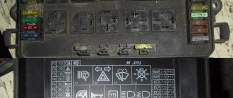
Relays and fuses VAZ 2114
F1 for 10 Amps (A) rear fog lights and rear fog light warning lamp. F2 for 10 A turn signal lamps, turn signal relay, hazard lights, hazard warning lights. F3 7.5 A lamps for interior lighting (both) and trunk, ignition lighting, powertrain control system control lamp, brake lamps, computer, if available. F4 20 A carrier, relay and rear window heating element. F5 20 A horn and its relay, cooling fan. F6 30 A power windows and their relays F7 30 A motor heater, headlight cleaner, windshield washer, cigarette lighter, glove compartment light bulb, rear window heating relay winding. F8 7.5 A right fog lamp. F9 7.5 A left fog lamp. F10 at 7.5 A left side marker, lamp signaling the inclusion of the side light, lamps for illuminating the sign, engine compartment, illumination of switches and instruments, instrument lighting switch. F11 at 7.5 A right side. F12 at 7.5 A right low beam. F13 at 7.5 A left low beam. F14 for 7.5 A left high beam and a light indicating that the high beam headlights are on. F15 at 7.5 A right far. F16 30 A - a light indicating insufficient oil pressure, brake fluid level, engagement of the parking brake, low battery, instrument cluster, relay for monitoring the health of lamps, indication of control systems, reversing lamps, turn indicators and their relays, as well as an alarm if turning mode is turned on, computer, generator excitation winding is turned on at the moment the engine starts.