If everything is clear with the main elements and arrow indicators, the indicators need to be deciphered.
The bulk of the light bulbs are located strictly in the center of the panel. There are 7 control indicators in the column; their explanation is presented in detail in the pictures below.
- The first thing to install from the top is turning on the turn signals. The indicator is activated when pressed or alarmed.
- Next is the check engine fault indicator. The light bulb is used only on injection engines.
- The third one from the top is a faulty battery. If the indicator lights up, this indicates a breakdown in the generator line (the battery is not charging).
- In the middle of the column there is a light bulb for turning on the dimensions. This indicator indicates normal operation of the device.
- An indicator for activating the main beam of the head optics is installed even lower. The blue indicator indicates that the exterior lights are operational and working properly.
- The penultimate light is an indicator of the critical oil pressure in the engine crankcase. If it lights up constantly, you need to add fluid to the required level or check the functioning of the pump.
- The last place the manufacturer placed the parking brake activation indicator. Usually the light comes on when the lever is raised.
Also on the dashboard you can see a yellow diode indicating a critically low fuel level in the tank.
The light comes on only when the container is empty and there is no more than 5 liters of gasoline remaining.
The instrument cluster is not equipped with an emergency warning symbol; it is located on the power button.
Identification of buttons
Several switch keys can be installed on the car’s dashboard, which are responsible for activating certain elements and parts of the car. The following is a description of the main buttons on the car dashboard.
| Number | Purpose |
| 2 | Turn on the sound signal. |
| 6 | Headlight position regulator. |
| 10 | Emergency button. |
| 13 | Heater switches. |
| 14 | Dashboard lighting. |
| 17 | The panel contains switches for external lighting, heater fan, foglights, and heated rear window. |
| 19 | A light that requires you to fasten your seat belt. |
| 20 | Reserve socket. |
VAZ 2107: exclamation mark on the panel
A similar indicator appeared on the dashboard only in modifications of recent years. The symbol indicates the need to check the brake system.
The battery light on the dash 2107 is on
The indicator looks like a red battery-shaped icon. If the symbol is constantly on, it is recommended to carry out a thorough diagnosis of the generator and supply wiring. If the problem is not found, check the battery.
ECON on panel 2107: what does it mean
A thoughtful but simply executed car detail. The dial indicator shows the fuel mixture consumption in real time. The option helps the driver save fuel.
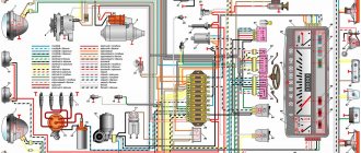
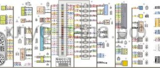
Scheme of VAZ 2107 carburetor produced 1988 - 2001 with generator 37.3701
The diagram of a VAZ 2107 carburetor is mounted on the principle of one wire. The negative current conductor is the body of the seven. Almost every wire laid inside the body of a VAZ 2107 serves as a positive conductor of electricity.
Front part of the diagram
| Position number on the VAZ 2107 carburetor diagram | Explanation of position |
| 1 | headlight |
| 2 | side turn lights; |
| 3 | battery |
| 4 | starter connection relay |
| 5 | carburetor electric valve |
| 6 | miniature carburetor switch |
| 7 | generator 37.3701 |
| 8 | headlight wiper motor |
| 9 | fan motor connection sensor |
| 10 | electric fan motor for engine cooling structure |
| 11 | signaling |
| 12 | ignition distributor |
| 13 | spark plugs |
| 14 | starter vaz 2107 |
| 15 | DUTOZH |
| 16 | engine compartment light |
| 17 | oil pressure indicator sensor |
| 18 | brake fluid level sensor |
| 19 | windshield wiper motor |
| 20 | carburetor electric valve control unit |
| 21 | ignition reel |
| 22 | electric motor for headlight washer pump |
| 23 | electric motor for windshield washer pump |
| 24 | fuse box VAZ 2107 |
| 25 | windshield wiper switch |
| 26 | hazard warning light and turn signal relay |
| 27 | brake light switch |
| 28 | rear light switch |
| 29 | ignition switch |
| 30 | ignition switch |
| 31 | three way switch |
| 32 | hazard warning light switch |
| 33 | electrical socket for carrying |
| 34 | heater fan switch |
Useful! VAZ 2107 fuse box
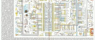
Back of the diagram
| Position number on the VAZ 2107 carburetor diagram | Explanation of position |
| 35 | additional resistor for electric heater motor |
| 36 | rear window heating indicator light |
| 37 | brake fluid level indicator light |
| 38 | signaling unit |
| 39 | electric heater fan motor |
| 40 | light bulb board |
| 41 | lamp switches on the front door pillars |
| 42 | front door open alarm lamp switches |
| 43 | front door open alarm lamps |
| 44 | terminal strip |
| 45 | cigarette lighter vaz 2107 |
| 46 | alarm |
| 47 | instrument light switch |
| 48 | diode for monitoring the health of the brake fluid level warning lamp |
| 49 | gasoline level indicator |
| 50 | gasoline reserve signal |
| 51 | speedometer |
| 52 | direction indicator connection signal light |
| 53 | carburetor throttle closing warning light |
| 54 | battery charging warning light |
| 55 | carburetor throttle warning switch |
| 56 | dashboard vaz 2107 |
| 57 | econometrician |
| 58 | light switches on the rear door pillars |
| 59 | antifreeze temperature indicator |
| 60 | tachometer |
| 61 | signal light for connecting the handbrake |
| 62 | low oil pressure warning light |
| 63 | signal light for connecting high beam headlights |
| 64 | signal light for connecting external lighting |
| 65 | voltmeter |
| 66 | handbrake warning switch |
| 67 | outside light switch |
| 68 | rear window heating switch with backlight |
| 69 | rear fog light switch with warning light |
| 70 | fog light circuit fuse |
| 71 | lamp |
| 72 | rear lights |
| 73 | gasoline level and quantity indicator sensor |
| 74 | terminal blocks for connecting to the rear window heating element |
| 75 | light bulbs numbers |
The sequence of conventional numbering of plugs in the blocks: a - headlights, headlight and windshield wipers, windshield wiper switches, carburetor electric valve control unit; b - fuse box and three-lever switch; c — emergency lights and turn signals; d — rear lights (numbering of pins in order from the edge of the board); d — hazard warning switch
Complete diagram of VAZ 2107 carburetor
In order to quickly find the necessary electrical circuits of specific devices and units, their local diagrams are located in additional subsections of this article.
Wiring diagram for connecting the adapter connector for checking the carburetor control unit
| Item no. | Explanation of the position on the diagram |
| 1 | ECU carburetor VAZ 2107 |
| 2 | voltmeter included in the adapter connector |
| 3 | pneumatic throttle |
| 4 | Ignition solenoid |
| 5 | view of the control unit plug connector |
Connection diagram for EPHH carburetor VAZ 2107
| Position number | Explanation of the position on the EPHH diagram of the VAZ 2107 carburetor |
| 1 | ecu for forced idle economizer (epkhh) VAZ 2107 |
| 2 | Ignition solenoid |
| 3 | small switch in the carburetor |
| 4 | pneumatic throttle |
| 5 | relay and fuse box |
| 6 | ignition switch. |
Helpful! Tightening torques for VAZ 2107
Removal and Replacement Guide
Changing the fuse box
Replacement of fuses and relays is necessary only if repair is impossible. To dismantle, follow these steps:
- The ground terminal is disconnected from the battery.
- The air filter housing is removed.
- All harnesses that fit the power supply unit are undocked.
- The shelf in the cabin under the dashboard and the glove compartment body are removed, and the harness with the connector is disconnected from the unit.
- Using a 10mm head, the block mount is unscrewed and the housing is removed along with the seal.
- The new device is installed in the reverse order.
Relays play an important role in the health of the system because they perform the operations to turn on or off the necessary functions in the car.
REFERENCE. The mounting blocks use two types of relays; they differ in design and operating principle:
- Electromagnetic component on and off relays are ordinary relays. Their contacts close and open when voltage is applied and removed.
- Specialized relays have a built-in compact electronic unit that turns certain components on and off.
To check the functionality of the relay, you must perform the following steps:
- The ground wire in the car is disconnected from the battery.
- The relay can be easily pulled out by hand.
- A visual inspection of the contacts is carried out, they are cleaned of oxidation, and the reliability of the pin fastenings is checked.
- Functionality testing is performed by applying 12V power to the winding using two pieces of wire.
- When power is supplied, the coil should operate, and the contacts should also close, which can be checked using a multimeter in the vertebrae or resistance measurement mode.
- The relay should be replaced with a new one if it is not working.
Pinout of fuse box 2107
In the photo, numbers from 1 to 6 indicate relays or connectors for their installation:
- Rear window defroster control.
- Control of windshield wipers and headlight washer motor (if equipped).
- Control of sound signals (a plug is installed instead of a relay).
- Connector for installing a fan motor control relay designed to cool the radiator (not used in new VAZ 2107 models).
- Control of high beam headlight bulbs.
- Control of low beam electric lamps.
The photo also shows components that perform various protection functions (from F1 to F17):
- F1 protects the circuits of: lamps in reversing lights; stove fan; heater (on indicator lamp and control relay), washer pump and rear window wiper.
- F2 protects windshield wipers.
- F3 is in reserve.
- F4 is in reserve.
- F5 protects the rear window heater.
- F6 - cigarette lighter circuit, connector for turning on a portable lamp, clock on the dashboard.
- F7 - cooling fan and signal fuse.
- F8 - control circuits for turn signals in emergency mode.
- F9 - protection of fog light circuits and generator voltage relays for a number of VAZ models.
- F10 protects the dashboard warning lights.
- F11 - circuits for turning on the stop lamps.
- F12 - right high beam headlight circuits.
- F13 - protection of the left high beam headlight and warning lamp.
- F14 - protection of the side light circuits of the headlights (front left and rear right), rear license plate light, engine compartment light.
- F15 - protection of the side light circuits of the headlights (front right and rear left), lighting of the cigarette lighter socket, glove compartment.
- F16 - right low beam headlight lamp.
- F17 - left low beam headlight lamp.
VAZ 2107 connection diagram
Electrical diagram for connecting the VAZ 2107 starter, model 35.3708
| Item no. | Explanation of the position on the VAZ 2107 starter connection diagram |
| 1 | generator VAZ 2107 |
| 2 | source of electricity |
| 3 | starter VAZ 2107 model 35.3708 |
| 4 | additional starter switch |
| 5 | mounting block |
| 6 | ignition switch |
Wiring diagram for outdoor lighting
| Position number | Explanation of the position on the external lighting diagram of the VAZ 2107 |
| 1 | side light bulbs in headlights |
| 2 | engine compartment lamp |
| 3 | mounting block vaz 2107 |
| 4 | ignition switch |
| 5 | instrument lighting designer |
| 6 | outdoor light switch |
| 7 | instrument cluster lamp |
| 8 | external lighting indicator lamp |
| 9 | side and fog lamps in the rear lights |
| 10 | license plate lights |
Sound signal connection diagram
| Item no. | Explanation of the position on the signal connection diagram |
| 1 | sound signals |
| 2 | mounting block VAZ 2107 |
| 3 | signaling switch (RZ); |
| 4 | horn switch |
Wiring diagram for connecting hazard warning lights and direction indicators
| Position number | Explanation of the position on the emergency signal diagram of the VAZ 2107 |
| 1 | turn signal lamps in headlights |
| 2 | side direction indicators |
| 3 | mounting block VAZ 2107 |
| 4 | ignition switch |
| 5 | hazard switch |
| 6 | hazard warning and direction indicator relay |
| 7 | turn signal lamps located in the rear lights |
| 8 | turn signal warning lamp located in the instrument cluster |
| 9 | turn switch |
Useful! Generator VAZ 2107
Generator device
Identification of light bulbs on the dashboard
The design of a car generator implies the presence of its own rectifier and control circuit. The generating part of the generator, using a stationary winding (stator), generates three-phase alternating current, which is then rectified by a series of six large diodes and the direct current charges the battery. Alternating current is induced by the rotating magnetic field of the winding (around the field winding or rotor). Next, the current is supplied to the electronic circuit through the brushes and slip rings.
Generator structure: 1.Nut. 2. Washer. 3.Pulley 4.Front cover. 5. Distance ring. 6.Rotor. 7.Stator. 8.Back cover. 9.Casing. 10. Gasket. 11.Protective sleeve. 12. Rectifier unit with capacitor. 13.Latch holder with voltage regulator.
The generator is located at the front of the car engine and is started using the crankshaft. The connection diagram and operating principle of a car generator are the same for any car. There are, of course, some differences, but they are usually associated with the quality of the manufactured product, the power and the layout of the components in the motor. All modern cars are equipped with alternating current generator sets, which include not only the generator itself, but also a voltage regulator. The regulator equally distributes the current in the excitation winding, and it is due to this that the power of the generator set itself fluctuates at a time when the voltage at the power output terminals remains unchanged.
The principle of operation of a car generator
Connection diagram for the VAZ 2110-2115 generator
The alternator connection diagram includes the following components:
- Battery.
- Generator.
- Fuse block.
- Ignition.
- Dashboard.
- Rectifier block and additional diodes.
The principle of operation is quite simple: when the ignition is turned on plus through the lock, the ignition goes through the fuse box, light bulb, diode bridge and goes through a resistor to minus. When the light on the dashboard lights up, then the plus goes to the generator (to the excitation winding), then during the process of starting the engine, the pulley begins to rotate, the armature also rotates, due to electromagnetic induction, electromotive force is generated and alternating current appears.
Next, the diode passes plus into the rectifier block through a sine wave into the left arm, and minus into the right arm. Additional diodes on the light bulb cut off the negatives and only positives are obtained, then it goes to the dashboard assembly, and the diode that is there allows only the negative to pass through, as a result the light goes out and the positive then goes through the resistor and goes to the negative.
The principle of operation of a car DC generator can be explained as follows: a small direct current begins to flow through the excitation winding, which is regulated by the control unit and is maintained by it at a level of slightly more than 14 V. Most generators in a car are capable of generating at least 45 amperes. The generator operates at 3000 rpm and above - if you look at the ratio of the size of the fan belts for the pulleys, it will be two or three to one in relation to the engine frequency.
To avoid this, the plates and other parts of the generator rectifier are partially or completely covered with an insulating layer. The heat sinks are combined into a monolithic design of the rectifier unit mainly by mounting plates made of insulating material, reinforced with connecting bars.
Next, let's look at the connection diagram for a car generator using the example of a VAZ-2107 car.
VAZ 2107 fuse diagram
Diagram of internal connections of the VAZ 2107 fuse box
| Here is an electrical diagram of the internal connections of the VAZ 2107 fuse mounting block. This diagram shows fuses, switching relays and plug connectors. The relays are shown with their internal electrical circuits. On the plugs, the number placed inside indicates the terminal number. The external designation Ш1, Ш2 and so on is the number of the plug connection. More comprehensive information is available on this page. |
Numbering, ratings and purpose of fuses
Each of the fuses in the VAZ 2107 can serve one or more electrical circuits of the car. If a fuse fails, a specific device or vehicle system (or several) will not receive power. As a result, a particular device becomes inoperable.
Fuse failure is not always the cause of a malfunction. In many cases, a blown fuse is the result of a component or system malfunction. Such cases include:
- short circuit in the car's electrical wiring;
- burning of contacts and connectors;
- wear of the fuel pump, electric motors of vehicle system drives (windshield wiper, fan);
- malfunction of the electronic engine control unit.
In the event of a failure of any of the vehicle systems, according to the table below and the fuse location diagram, determine the fuse number and its location in the block. If this fuse is responsible for several systems, you should check the functionality of the other system. If it works correctly, the fuse is most likely good and is not the problem. After this, using a multimeter or other measuring equipment, the functionality of the fuse is checked by measuring its resistance (continuity).
Testing the fuse should only be done on a dismantled (removed) fuse. The resistance of a good fuse is close to zero. In most types of fuses, the thread of its working area is visible through the light or is located outside the body part. You can check the fuse visually, but there are often cases of erroneous inspection when the working area has a microcrack.
Electrical ignition circuit for VAZ 2107
Ignition circuit for VAZ 2107 with a classic contact device
This electrical diagram shows the classic contact ignition system of the VAZ 2107. All devices included in this ignition circuit of the VAZ 2107 are shown with their own electrical block diagram. It allows you to better understand their operation and correctly connect these devices to the ignition electrical circuit. The VAZ 2107 ignition circuit starts from the fuse mounting block, passes through the ignition relay, ignition switch, ignition coil, ignition distributor and ends at the spark plugs.
| Item no. | Decoding the position on the ignition diagram 2107 |
| 1 | relay and fuse block |
| 2 | ignition switch |
| 3 | ignition switch |
| 4 | Ignition solenoid |
| 5 | ignition distributor |
| 6 | spark plugs |
Wiring diagram of a non-contact ignition system
| Item no. | Explanation of the position on the diagram of the contactless ignition system of the VAZ 2107 |
| 1 | ignition switch |
| 2 | ignition stick |
| 3 | mounting block for relays and fuses |
| 4 | Ignition solenoid |
| 5 | switch vaz 2107 |
| 6 | ignition distributor sensor |
| 7 | spark plugs |
LED panel lighting
The most popular tuning is the LED lighting of the VAZ 2107 instruments, which makes the torpedo attractive, especially at night.
To perform tuning, you will need to prepare:
- 10 light bulbs 3 V each;
- special train;
- a piece of wire from a molex connector;
- resistor with a resistance of 680 ohms.
Tidying with LED backlight
The procedure consists of three stages:
- First you need to prepare the LEDs by cutting off their heads. Then you need to cut the molex wire into 3 cm pieces and bend them in the shape of the letter “L”. The prepared wires need to be soldered in the places where the LEDs will be placed.
- The next step is trimming the LEDs. You need to form wires from the cut cable and use them to connect 4 LEDs into one circuit.
- The brightness is adjusted using the adjustment knob. You need to adjust the brightness in each of the two circuits containing 4 LEDs. You need to drive very carefully with this kind of lighting.
VAZ 2107 wiring diagram
Electrical wiring diagram for the VAZ 2107 stove
| Item no. | Explanation of the position on the stove wiring diagram |
| 1 | relay and fuse block |
| 2 | ignition switch VAZ 2107 |
| 3 | heater electric motor switch |
| 4 | additional resistor |
| 5 | electric heater fan motor |
Brake warning lamp wiring diagram
| Item no. | Explanation of the position on the brake warning lamp diagram |
| 1 | brake fluid level meter |
| 2 | mounting block vaz 2107 |
| 3 | ignition switch |
| 4 | handbrake control relay |
| 5 | handbrake control switch |
| 6 | instrument cluster with handbrake control |
| 7 | checking the brake fluid level |
Wiring diagram (location of wiring harnesses) VAZ 2107 carburetor in the engine compartment
| Position number on the VAZ 2107 diagram | Explanation of the position on the wiring diagram | Article number |
| 1 | wiring (harness) of the right mudguard | 21050-3724016-72 |
| 2 | battery wiring harness | 21050-3724070-02 |
| 3 | battery wiring (harness) | 21044-3724080-10 |
| 4 | left mudguard wiring harness | 21070-3724017-02 |
| 5 | bundle of wires (wiring) of the ignition distributor | 21010-3707080-00 |
| 6 | high voltage wire | 21010-3707150-00 |
This wiring diagram is mounted on models VAZ-2107, VAZ-2107-01, VAZ-21074-01, VAZ-21074-02
Location of wiring harnesses (wiring diagram) VAZ 2107 injector in the engine compartment
| Position number on the VAZ diagram | Explanation of the position on the wiring diagram | Catalog number |
| 1 | Right mudguard wiring harness | 21073-3724016-00 |
| 2 | Ignition wiring (harness) | 21073-3724026-00 |
| 3 | Battery wiring harness | 21050-3724070-02 |
| 4 | Battery wiring (harness) | 21044-3724080-10 |
| 5 | Injector wiring harness | 21214-3724036-00 |
| 6 | Wiring (harness) of the left mudguard | 21073-3724017-00 |
| 7 | Ignition module wiring harness | 21214-3707080-10 |
This wiring diagram is installed on models VAZ-2107-20, VAZ-2107-21, VAZ-21074-21
Wiring layout for the VAZ 2107 body
| Position number on the VAZ diagram | Explanation of the position on the wiring diagram | VAZ catalog number |
| 1 | Fuel level sensor wiring harness | 21073-3724037-00 |
| 2 | Instrument panel wiring (harness) | 21070-3724030-41 |
| 3 | Additional wiring harness | 21044-3724100-00 |
| 4 | Rear wiring harness | 21050-3724210-03 |
| 5 | Ground wire for fuel level indicator sensor | 21030-3724220-00 |
| 6 | Ground harness (wiring) for license plate lights | 21050-3724214-00 |
| 7 | Ground wire | 21020-3724220-00 |
This wiring diagram is mounted on models VAZ-2107, VAZ-2107-01, VAZ-2107-20, VAZ-2107-21, VAZ-21074-01, VAZ-21074-02, VAZ-21074-21
How to replace dashboard lamps?
Well, firstly, before carrying out any electrical work in the car, it is necessary to turn off the power to the vehicle’s on-board network. To do this, open the hood and remove the negative terminal of the battery.
How to change light bulbs on a VAZ 2107
Inside the car, use a flat-head screwdriver to pry and pull out the plastic handles on the heater air damper control drive. After this, unscrew the nut located on the small handle designed to reset the daily mileage. Then remove the washer from it and push the handle deep into the instrument panel.
During the replacement process, it is possible to install lamps with a different color of luminous flux, however, in no case should you use lamps with too much or too little power in order to avoid other malfunctions.
VAZ 2110 (new model) - changing the backlight with your own hands
What kind of lighting do you prefer?
Built-in Chandelier
Electrical cooling circuit for VAZ 2107
| Position number | Explanation of the position on the VAZ 2107 cooling system diagram |
| 1 | cooling fan motor |
| 2 | motor switch sensor |
| 3 | relay and fuse block VAZ 2107 |
| 4 | ignition switch |
| 5 | ignition relay |
| 6 | motor start relay (P4) |
Installation instructions
For installation, in addition to the GAZ Volga dashboard itself, you will also need car wires and heat shrink. And several terminals for pins XP 1, XP 2, XP 3, XP 4. You can find everything you need at an auto parts store. The part itself must be accompanied by instructions for its assembly.
To replace the old shield with a new one, you should follow these steps.
- First, remove the 4 screws that secure the panel. Also, 6 screws of the column casing, remove it.
- Now unscrew the 4 screws that secure the shield itself.
- After disconnecting the 5 XP connectors, remove the part.
- Now you need to connect the wiring using the instructions for your specific panel model and XP terminals.
- Turn off the ABS and EBD indicators if your car does not have such devices.
- Install in the reverse order of dismantling.
Photo gallery “Panel and shield”
VAZ 2107 generator circuit
Electrical circuit of the generator model 37.3701
| Item no. | Explanation of the position on the generator circuit 2107 |
| 1 | power supply |
| 2 | generator |
| 3 | relay and fuse block VAZ 2107 |
| 4 | ignition switch |
| 5 | battery charge control |
| 6 | voltmeter |
Electrical circuit of the generator brand G-222
| Item no. | Explanation of the position on the generator circuit G 222 |
| 1 | battery |
| 2 | internal diagram of the VAZ 2107 generator carburetor |
| 3 | battery charge control stick |
| 4 | relay and fuse block |
| 5 | ignition switch VAZ 2107 |
| 6 | battery charge control |
| 7 | voltmeter |
Advantages of installing a three-level regulator
The three-level voltage regulator on the VAZ 2107 is capable of maintaining a constant voltage supplied by the generator to the vehicle network. With this product it is possible to save and increase the battery life. In addition to regulating voltage, three-position regulators are capable of maintaining current within a certain range.
Some of the main advantages of the device in question include:
- The main board of the device is located not in the generator itself, but away from it, which contributes to less heating of the product, as well as extending its service life.
- Possibility to regulate the voltage level manually thanks to a special switch. The device operates from a switch.
- The charge level is significantly higher, in contrast to standard products.
Problems with starting the engine, especially on frosty days when it is very difficult for the starter to start the engine, can be avoided by replacing the standard device with a three-position one. Large loads on the electrical circuit in a car, such as headlights, heater, heated glass, can contribute to battery discharge, even if the engine is running and the standard product is in good working order.
Types of regulator relays are simple, three-level and with temperature compensation. In the brush section of a standard seven generator, in most cases, a temperature-compensated option is installed. But, as practice shows, in terms of thermal regulation, these regulators are mostly ineffective. Recently, among drivers of the VAZ 2107 and other Lada models, the three-level type is gaining more and more popularity. Car owners who have installed such a regulator overwhelmingly recognize it as more effective than the standard one.
Characteristics of the Energomash device for VAZ 2107
The Energomash voltage regulator for the VAZ 2107 is equipped with three “25C” type diodes and a mode switch. With their help, a three-stage voltage change is carried out. A three-level balancer is also called a current injector, since the device is capable of maintaining it at a level of up to 6A. The main functionality of the three-level voltage regulator for the VAZ 2107 model "Energomash" is based on changing the current from the generator, thereby increasing the voltage of the on-board circuit to 13.6-14.7 V.
The first operating mode provides for maintaining the voltage at the generator output at 13.6 Volts. The switch should be installed in a position where the ambient temperature is +20 degrees and above. The switch in the neutral position should be set at temperature values from 0 to +20 degrees. And in the third position, the generator will produce a voltage of 14.7 V when the air temperature is from 0 to -20 degrees.
It is important to know! The Energomash model will cost about 350 rubles
Changing the brush assembly
Replacing a standard product with a VAZ-2107
Connecting a three-position regulator, or rather, changing a standard product, does not present any difficulties. After purchasing the product, you must complete the following steps:
- Initially, you need to remove the protective cover of the generator. Don't forget to disconnect the negative terminal from the battery.
- The standard part is removed by unscrewing two bolts using a screwdriver or a “6” key, which depends on which VAZ generator is installed on the car. It is also necessary to remove the terminal.
- After this, we compare the standard device with the three-level one. The brushes and fasteners must be identical in design, otherwise the product will need to be replaced.
- A new product is installed in place of the standard “tablet”, after which it is fixed with fasteners (bolts).
- The body of the product should be secured to the ground of the car in any convenient place (pictured below). This is not difficult to do, since the wire is long enough.
After installing such a product, the owner of a VAZ-2107 car will be able to forever forget about constant problems with a dead battery, since the new regulator will recharge it more stably under certain temperature conditions.
VAZ 2107 headlight diagram
Wiring diagram of headlights and fog lights
| Item no. | Explanation of the position on the diagram of headlights and fog lights |
| 1 | headlight bulbs |
| 2 | mounting block VAZ 2107 |
| 3 | ignition switch |
| 4 | headlight switch |
| 5 | size switch |
| 6 | rear fog light switch |
| 7 | high beam headlight control |
| 8 | foglight control; |
| 9 | fog lights and tail lights |
| P5 | Relay for high beam headlights |
| P6 | low beam headlight switch |
Headlight adjustment diagram
| Item no. | Explanation of the position on the VAZ 2107 headlight adjustment diagram |
| 1 | horizontal light beam adjustment screw |
| 2 | headlight housing |
| 3 | terminal block |
| 4 | set screw |
| 5 | screw for adjusting the light beam in the vertical direction |
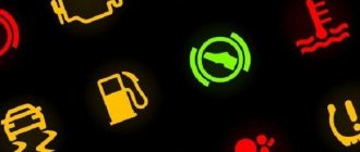
How are the icons on the installed instrument panel deciphered?
In addition to the instruments, the panel also has various icons that light up when there is a malfunction in the form of electronic indicators. They have the following meanings for the driver:
- ABS sign. This indicator lights up only when the engine starts and immediately goes out. It can also light up if there are problems with the operation of the anti-lock elements in the brake system.
- Front airbag indicator. Will light up when there is a malfunction with the airbags attached to the front panel of the car.
- An indicator that reminds you to put on your seat belt. It will light up when you start the engine and will remain on until you fasten your seat belt.
- Airbag warning light. Lights up when the airbag of the front pair of passengers is turned off.
- Heated rear window indicator. It will light up before turning on the heating on the rear window.
- Low beam icon.
- High beam indicator.
- Sign for turning on the rear fog lights.
- Front fog lamp sign.
- An indicator that turns on when there is a malfunction in the electric amplifier.
- Signal lamp that operates when the doors are not closed.
- Lamp for adjusting the fuel level in the tank. It lights up only if there is fuel for 15-20 minutes of driving.
- Indicator for left and right turn signals of the vehicle.
- An indicator that turns on when the engine cooling system overheats.
- Indicator lamps that turn on when the batteries are low charged.
- A light called “CHECK ENGINE.” Lights up when a malfunction occurs with the engine control system.
- Signal indicators that turn on when the parking brake is used or when a breakdown occurs in the brake system.
- Indicator of low pressure and level of engine oil in the lubrication system.
- The preheating system malfunction light (specifically responsible for the glow plugs).
- A warning light that appears when the electronic engine starting system of a car is blocked.
Advice: if one of the indicators associated with the wheels lights up, then first bleed the brakes on the VAZ-2110. and then check the system again. If the indicator on the on-board panel disappears, it means that the problem was solved by repairing the brake system.
Electrical diagram of the VAZ 2107 panel
| Item no. | Explanation of the position on the panel diagram |
| 1 | oil pressure indicator sensor |
| 2 | antifreeze heat indicator sensor |
| 3 | oil pressure sensor |
| 4 | mounting block VAZ 2107 |
| 5 | sensor for level indicator and gasoline reserve |
| 6 | Gasoline level and reserve indicator |
| 7 | tachometer |
| 8 | antifreeze heat indicator |
| 9 | oil pressure gauge with control |
| 10 | ignition switch VAZ 2107 |
| 11 | pneumatic valve control unit |
| 12 | ignition coil. |
Instrument cluster connection block diagram (rear view)
| Position number | Explanation of the position on the wiring diagram of the VAZ 2107 dashboard |
| 1 | voltmeter |
| 2 | fuel level indicator with reserve warning lamp |
| 3 | instrument lighting lamps |
| 4 | speedometer |
| 5 | carburetor air damper warning lamp |
| 6 | turn signal indicator lamp |
| 7 | tachometer |
| 8 | econometer VAZ 2107 |
| 9 | coolant temperature gauge |
| 10 | parking brake warning lamp |
| 11 | oil pressure warning light |
| 12 | high beam warning lamp |
| 13 | side light indicator lamp |
| 14 | battery charge indicator lamp |
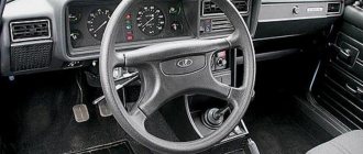
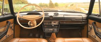
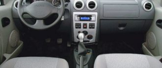
What does the panel consist of?
The panel consists of a large number of elements that are responsible for the operation of certain components of the VAZ 2107 car. The instrument panel is located in the car interior and is directly embedded in the dashboard on the driver’s side. The main elements are located under a special plastic transparent glass, which protects them from mechanical damage. The elements of the instrument panel include the following elements:
- Accumulator charging;
- speedometer;
- odometer;
- tachometer;
- motor temperature sensor;
- ECON – instantaneous fuel consumption indicator;
- additional signaling elements;
- resettable odometer;
- and 10 – fuel level in the gas tank and warning light.
Let's briefly look at the purposes of each of these elements.
Instrument distribution diagram on the control panel of a VAZ 2107 car
- Speedometer. The device located on the right side of the panel is called a speedometer. Serves as an informant for the driver about the speed of the vehicle. The scale has values from 0 to 180, which indicates the speed of the vehicle. There are two dials on the device that keep track of the distance traveled by the “seven”. One of them has the ability to adjust, but the bottom one does not.
- Tachometer. The device located on the left side serves to inform the owner about the crankshaft rotation speed in relation to a unit of time. Most drivers do not really understand the purpose of this element and rarely pay attention to it. But this element is very important, since it is a direct indicator of the quality of engine operation. The closer the arrow gets to the red mark, the more the motor is overloaded. And when it crosses the red line, the car’s movement should be stopped immediately, since the engine is operating in critical mode.
- ECON flow indicator. The indicator, located in the upper left corner of the instrument panel, performs the function of indicating the consumption of the fuel mixture in instantaneous time while the engine is running. When driving at speeds above 90 km/h, fuel consumption increases and the arrow moves to a yellow position. A very useful feature for the driver to be able to save fuel.
- Temperature indicator. Designed to indicate the motor temperature value. Above 100 degrees Celsius, the needle moves to the red mark, which indicates overheating.
- Fuel indicator. Using this indicator, drivers determine the amount of fuel in the tank, which is transmitted through an electronic sensor and level.
- Battery charge. Indicates how good the battery is; position on the red mark indicates the need to recharge.
Windshield wiper and washer diagram for VAZ 2107
Electrical circuit for switching on the windshield wiper and washer
| Item no. | Explanation of the position on the diagram of windshield wipers and washers 2107 |
| 1 | windshield washer motor |
| 2 | electric wiper motor |
| 3 | mounting block |
| 4 | ignition switch VAZ 2107 |
| 5 | wiper switch |
| 6 | wiper switch |
Electrical circuit diagram for turning on the headlight cleaners and washer
| Item no. | Explanation of the position on the diagram of headlight cleaners and washers 2107 |
| 1 | electric headlight wiper motors |
| 2 | electric headlight washer motor |
| 3 | mounting block VAZ 2107 |
| 4 | ignition switch |
| 5 | headlight washer switch in the three-lever switch (at the same time it is a windshield washer switch); |
| P2 | Relay for turning on the wipers and headlight washers |
Description of the panel, disadvantages, advantages
GAZ-3110 has a standard instrument panel, consisting of three main round dials and two secondary ones located on the sides. Here's the information a driver can glean from their performance:
- current speed and total mileage;
- engine speed;
- oil level and quantity;
- battery charge;
- amount of gasoline.
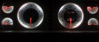
The instrument panel is designed in a gray tone, does not have any bright details, and is difficult to use at night. Many users often look for a replacement for it or introduce additional elements into it to improve functionality.
Dashboard lighting for car Gas 3110
In general, the new version of the panel has positive reviews, since it is a little more convenient to use than the old one. Before installing this model, you should carefully study the instructions for its use.
Diagram of VAZ 2107 injector (VAZ 21073-40)
The VAZ 2107 differs from the VAZ-21073-40 in the configuration of a 1.7 liter engine with central gasoline injection. On these engines, instead of the functioning of the carburetor, a central injection unit is mounted on the intake pipe; it contains a nozzle that supplies fuel according to ECU commands
The electrical circuit of the electrical equipment of the VAZ-21073-40 differs from the VAZ 2107 in the addition of the central injection system harness, the wires of which connect the ECU to the sensors and actuators of the injection system. Three wires, from the injection system harness, through a separate block, are connected to the low-voltage input of the tachometer on the instrument panel, with a separate “SNESK ENGINE” display and to pin 15 of the ignition switch.
The electric motor 26 of the engine cooling system fan is connected by the injection system control controller 15. Therefore, the radiator does not have a sensor for connecting the electric fan motor.
Electrical diagram of VAZ-21073-40 central injector
| Position number | Explanation of the position on the VAZ 2107 injector diagram |
| 1 | electric gasoline pump with gasoline level sensor |
| 2 | central injector sprayer VAZ 2107 |
| 3 | oxygen concentration sensor |
| 4 | octane potentiometer |
| 5 | air heat meter |
| 6 | absolute pressure device |
| 7 | TPDZ |
| 8 | DTOZH |
| 9 | idle air control |
| 10 | diagnostic block |
| 11 | speed meter |
| 12 | canister purge throttle |
| 13 | spark plugs |
| 14 | VAZ 2107 ignition module |
| 15 | ECU block |
| 16 | intake pipe heater fuse |
| 17 | injection system fuse |
| 18 | injection system fuses |
| 19 | injection system fuses |
| 20 | DPKV |
| 21 | connection block to the instrument panel wiring harness |
| 22 | instrument panel with tachometer |
| 23 | display with control lamp “SNESK ENGINE”; |
| 24 | car ignition switch |
| 25 | fuse box VAZ 2107 injector |
| 26 | electric motor cooling fan |
| 27 | injection system ignition switch |
| 28 | connector for connecting an electric gasoline pump |
| 29 | intake pipe heater relay |
| 30 | intake pipe heater |
| P4 | relay for connecting the electric fan motor |
| A | to the “+” contact of the battery |
| IN | to pin “15” of the ignition switch |
Diagram of the engine control system VAZ 2107 injector
Electrical connection diagram for the VAZ 2107 injection engine control system
| Position number | Explanation of the position on the VAZ 2107 injector diagram |
| 1 | ECU contacts |
| 2 | Mass air flow sensor |
| 3 | DTOZH |
| 4 | DPKV |
| 5 | TPDZ |
| 6 | lambda probe VAZ 2107 injector |
| 7 | speed meter |
| 8 | ignition module |
| 9 | canister purge solenoid valve |
| 10 | electric fan switch |
| 11 | electric gasoline pump relay |
| 12 | main relyushka |
| 13 | fuse protecting the power circuit of the electric fuel pump |
| 14 | fuse protecting the power circuits of the main relay |
| 15 | fusible insert |
| 16 | fuse protecting the continuous power supply circuit of the computer |
| 17 | diode |
| 18 | empty control |
| X1 | diagnostic connector VAZ 2107 injector |
| X2 | connection block to the car electrical equipment system |
Possible malfunctions and ways to eliminate them
Incorrect operation of the indicators on the instrument panel is usually associated with problems with the system sensors.
It is with him that the system receives all the information. Before you begin repairing the panel, you should check whether the sensors themselves are operational. If everything is fine with them, but the data is not displayed or is displayed with distortions, the problem may also be hidden in the wiring. Another common problem is the burnout of individual instrument bulbs. They are quite easy to replace at home. True, you may have problems finding new parts, since car production has long been discontinued. But you can find suitable ones in any good radio electronics store or auto shop.
From the video below you can learn how to replace light bulbs (the author of the video is NONAvto).
Models of Lada VAZ 2107
- VAZ-2107 is a small passenger car with a closed monocoque four-door sedan-type body. Carburetor engine with a displacement of 1.45 liters of the VAZ 2103-08 brand with toxicity standards R-83. The maximum speed of the car is 150 km/h. It had the “Standard” package and was produced for the domestic market.
- VAZ 2107-01 - was equipped with two types of carburetor engine: 2103-08 carburetor, 1.45 liters; 2103-07 carburetor, 1.45 l. On the 2103-07 engine, a valve cover made of antiphon was installed. It has a maximum speed of 150 km/h. It has the “Norma” package and was produced for the domestic and foreign markets.
- VAZ 2107-02 - differs from the head model VAZ-2107 by an engine with a displacement of 1.45 liters and a system with distributed gasoline injection. The controller of the following models 2104-1411020-00 (01, 02) was installed. Equipped with a VAZ 2104 engine. It has a maximum speed of 145 km/h. It has the same five-speed gearbox. Has the “Standard” package. Produced for the domestic and foreign markets.
- BA3-21073 - differs from the VAZ-2107 car in its engine with a displacement of 1.3 liters and a central fuel injection system.
- VAZ-21074 differs from the VAZ-2107 by an engine with a displacement of 1.6 liters. The passenger car was equipped with an engine of two models: 2106-13 - carburetor; 21067-10 - with distributed fuel injection. The injection engine was developed to meet Euro-2 toxicity standards.
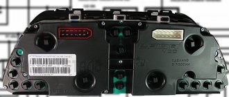
Removing the standard instrument cluster
Removing the factory panel from a VAZ 2107 is quite simple; it is installed in a niche on special brackets and secured to them with screws. The procedure for dismantling the equipment is as follows:
- We disconnect the battery by disconnecting the negative wire from the corresponding terminal of the battery.
- Using a flat-head screwdriver, remove the handles from the control levers of the interior ventilation and heating system.
- We unscrew the locking nut of the daily counter reset handle with a wrench and remove it together with the washer.
- We take out the plug for the screw securing the decorative panel and unscrew it.
- With a slight turn, we take the assembly out of the niche and gain access to the instrument cluster.
- By hand, unscrew the union nut securing the speedometer cable to the device and undock it.
- We remove the tube from the econometer fitting and disconnect three electrical connectors.
After this, the decorative panel with the instrument cluster is completely removed from the niche and you can work with it on the table. As can be seen from the description presented, dismantling this device on a VAZ 2107 car is not particularly difficult and can be done by a car enthusiast independently.