The concept of an interface between an object controlled by computerized equipment and a device performing monitoring and diagnostic functions implies strict standardization of the information exchange protocol. In the case of a car, there is a need for this, but manufacturers are not very interested in uniformity.
However, at the legislative level, it was still possible to create something standard, convenient for inspection organizations and private enterprises for diagnostics and repairs. This is an OBD II diagnostic interface connector, which almost all cars are now equipped with.
Diagnostic history with OBD II
Initially, few people cared about the convenience of automotive diagnosticians. Microcomputers that control the machine’s components could be checked using dealer tools that are not available for free sale and are not provided with open source codes. Therefore, the first step was taken by government organizations designed to monitor the environmental cleanliness of transport.
A control standard appeared in the United States, where California has always been famous as the most demanding state in limiting environmental pollution from internal combustion engines.
On the subject: What is a CAN bus in a car (device and connection diagram)
By the mid-90s, the description of the connector was finally formed in the form of OBD II, that is, the second final version. On-Board Diagnostics II became mandatory for all vehicles in the United States after 1996.
What is EOBD
The abbreviation EOBD does not add much meaning to the concept of OBD, and there is not even an exact definition of what the additional letter at the beginning means.
It could be an abbreviation for European, a hint at additional Enhanced abilities, or simply a meaningless Electronic prefix (there are simply no others).
But more often they are inclined to begin introducing a positive American standard into the production of European cars. Moreover, the US market has always been considered the most important.
As a result, in parallel with the American standards for the diagnostic interface SAE, global ISOs were also formed.
In most cases, they are identical, but with different alphanumeric designations, and more often the one that appeared earlier is used. This applies to physical and logical layer protocols.
Notebook-specific
It’s worth saying a few words about rare, I would even say “exotic” connectors that are found in laptops or some other devices, but which cannot be found on a regular PC. These are two connectors: PCMCIA (ExpressCard) and Kensington Lock. The latter is used to protect the device from theft. A special cord with a lock is inserted into the “Kensington Lock” connector and tied to any object, be it a table or a battery, for example. Naturally, only you have the keys to the castle.
ExpressCard
Kensington Lock
But the “ExpressCard” is a narrow slot covered with a plug into which a certain expansion card is inserted, on which ports for connecting other devices can be placed. With the help of such a card, you can easily add some USB 3.0 ports to your laptop, if only because there is a shortage of them on any laptop.
Well, that’s all, we have sorted out all the types of connectors that can only be found in a computer, if I suddenly missed something (the article is long, you understand) - write about it in the comments. Good luck to you and see you soon on the pages of pc-information-guide.ru!
Main function of the diagnostic connector
The diagnostic connector is necessary to enable communication between an external control computer and the vehicle’s internal computing resources. Through it, information is visualized on monitors and can be read and analyzed by car service specialists.
This makes it possible to quickly and promptly find a fault, thereby, from the point of view of legislators, to quickly prevent environmental violations, and the craftsmen received a tool with which they were gradually able to perform the same service procedures as official dealers.
Where is
The location of the connector is also standardized; the distance from the steering wheel should not exceed 16 inches; moreover, absolutely precise locations are indicated in several options for mounting the connector.
Usually it is covered from contamination, but the exact location in a particular car and the method of access are well known to repairmen.
OBD 2 connector pinout
Obviously, the purpose of all contacts in such a system must be clearly stated. A standard 16-pin connector is used. and the most important connections are uniquely linked to contact numbers (pins):
- the positive and negative lines of the SAE J1850 type interface are routed to 2 and 10 contacts, respectively;
- similarly, the High and Low lines of the CAN bus (ISO 15765-4, SAE J2284) use pins 6 and 14;
- A low-speed CAN bus can also be output to free contacts;
- Pins 7 and 15 are used for K-line and L-line interfaces ISO 9141-2 and ISO 14230;
- pins 4 and 5 are reserved for power and signal grounding and can simply be connected together with a jumper;
- constant power of 12 Volts, regardless of whether the ignition is turned on, is supplied to pin 16;
- the remaining contacts are not strictly standardized; manufacturers often use them at their own discretion, for example, to supply power supply after the ignition switch or main relay, output the fuel pump power wire or switch immobilizer circuits.
The use of certain contacts can be determined visually; usually, if the circuit is not used, then the pin in the socket is completely absent.
Improvement of the OBD connector for the VAZ 2110: independent connection of the ELM 327 adapter
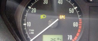
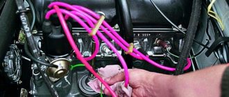
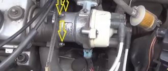
There is a special “CheckEngine” light on the dashboard of the VAZ 21110 car. When the ignition is turned on, the light comes on and while the vehicle’s internal combustion engine is not running, a special program reads data from all units and systems of the vehicle, transmitting data on fault detection to the on-board computer.
If, after starting the vehicle’s internal combustion engine, the “check” does not go out for another 10 seconds, it means that faults in the system have already been identified and the corresponding error codes have been entered into the memory of the on-board computer.
VAZ 2110 cars are equipped with a “January-4” controller, which does not provide feedback and the “check” lights up and there is a fault detection signal. Error codes in such a controller are calculated starting from “12” and ending with “61”.
We also recommend reading the article about how the engine ECU works and what it is. From this article you will learn about the purpose of the ECU, how this controller works, as well as what malfunctions occur with this element.
The codes are deciphered either with a special diagnostic device or independently. Using the example of the VAZ 2110 “January-4” ECU, we will consider the algorithm for performing diagnostics independently:
- connect contact “B” of the diagnostic block and “ground”;
- turn the ignition key to the third position without starting the car;
- the “CheckEngine” light illuminates the code “12” (the light flashes once -1, after a pause of two seconds it flashes twice in a row -2 flashes three times in a row (the program has started diagnostics);
- the program will detect the malfunction by displaying the corresponding error codes (flash, pause).
Some tips for installing a modern ELM 327 adapter with the OBD-II program (protocol) for the VAZ 2110:
- purchase an adapter along with a cable;
- study the installation instructions (pinout of the block and location of each connector);
- You must insert your own cable into each connector of the block, checking the pinout; it must comply with the manufacturer’s instructions.
Let us also add that programs for determining faults of the ELM 327 adapter are downloaded from various sources on the Internet.
Protocol classification
It was not possible to bring everything to a single exchange protocol, since the system was developed and implemented by many manufacturers at once, and then continuously improved, which continues to this day.
It is also surprising that there are relatively few protocols. In aggregate, they can be counted about nine, although if you notice all the differences, then there are many more. But there are no special problems with compatibility; the scanners include all interfaces, from the first to the most advanced.
A
Class A protocols are the lowest speed, but at the same time simple, based on traditional computer serial interfaces, that is, they do not require significant power in the form of converting microcontrollers. Speed up to 10 kbps. This is what is called K-line.
B
Slightly faster and more complex interface serial protocols, better protected from interference, use various types of digital signal modulation. The speed is approximately 5-10 times higher.
C
So far the most modern protocols, these include the CAN bus, that is, the speed is about 500 kbit/s, the bit depth of code messages has been increased and other algorithms have become more complicated. Good noise immunity of a differential signal from a twisted pair.
ISO9141 protocol
It contains two wires K and L, although exchange is quite possible via a bidirectional K-line, without control via L. Previously, “laces” were widely used - universal K-line adapters. It works quite reliably, but very slowly.
J1850 VPW
Belongs to the group of protocols of the American J1850 standard. Used on GM vehicles. It works five times slower than the completely similar J1850 PWM used by Ford.
Interfaces differ in physical implementation, one- or two-wire lines, modulation in latitude or duty cycle. Described in one standard.
On the back wall of the system unit
There are many connectors on the back of the system unit, some of which completely duplicate those located on the front. Their number can be completely different, again, it all depends on the motherboard model.
PS/2
Today this connector is considered obsolete, but on many motherboards it is still present and feels good, so to speak. Used to connect a mouse or keyboard. It is noteworthy that there are adapters from USB to PS/2.
COM port
It is almost impossible to find a COM connector on modern motherboards. Previously, it was used to connect all sorts of printers and other peripheral devices, which are now connected via USB. The COM port has an analogue - LPT, which is even less common; it has an oblong shape and is painted pink.
USB ports
As a rule, if there are 4 of these connectors in front, then at the back there are at least no less. Again, everything is done so that you can connect as many devices as possible to your computer at the same time. And if the front ports are usually occupied by all kinds of flash drives, then the rear ports are often connected to “long-lasting” devices, that is, which you will not constantly connect/disconnect. Well, for example, it could be a keyboard with a mouse, as well as printers and scanners.
There are two main types of these ports:
- USB 2.0
- USB 3.0
Of course, the third version is preferable due to its higher throughput; such a port is even marked in a different color - blue.
USB 2.0 and 3.0 are compatible with each other.
Network and Internet
One single connector is responsible for the network and the Internet - “Ethernet”, which is also sometimes called “RJ 45”. If you look closely, you will notice that there are small “windows” on this connector - these are indicators of network operation; when data is being transferred, they signal this. If the indicators do not light up, most likely the connector has stopped working and needs to be re-crimped (using a special crimp).
Video
Any monitor is connected to a computer (motherboard) using video connectors, which are located at the back. There are quite a lot of their varieties, it would not be entirely appropriate to talk about each one here, especially since the site already has a separate article about video connectors. In my opinion, only three of them can be called the most popular video ports:
- analog VGA port
- digital DVI
- digital hdmi
The rest are not so popular and are rare.
Audio
Usually - three or six inputs for connecting several speakers and a microphone. On budget segment boards, the number of audio connectors usually does not exceed three, but at the same time, all the necessary functionality is present, and this is:
- Red - for microphone;
- Green - for speakers;
- Blue - for connecting external sources, such as a TV, player or radio.
If your motherboard has six audio outputs, then know that the other three are used to connect additional speakers and a subwoofer.
Deciphering errors using the OBD2 system
Common to all manufacturers are DTC (Diagnostic Trouble Code) error codes, which are not always followed by everyone, but they strive for this. Typically each code contains four or five characters.
First sign
It can be one of four letters:
- B – body, that is, the code refers to body equipment, interior, etc.;
- P – power unit;
- C – chassis;
- U – network support.
This localization is designed to make it easier to work with codes in the early stages, without decryption.
Second sign
The second character approximately refers to the encoding as standard at the ISO level or used by the manufacturer. There is no unity here yet. "0" is an ISO or SAE code page.
Third sign
Specifies the subsystem where the malfunction occurred. According to the tables that list all the codes, this could be ignition, power supply, electronic support, transmission elements and other groups of devices.
Fourth and fifth characters
These signs act as a two-digit code that specifies the error that occurred. For example, a break, a short circuit, an omission, or values falling outside the acceptable range. They look like a good clue to the diagnostician, although not always.
How to protect?
The OBD connector must be accessible. However, to prevent unauthorized access, care should be taken to secure or lock this connector.
There are three options for protecting the OBD connector and limiting access to the ECU.
Let's take a closer look at each of them.
1. Move the connector to a hard-to-reach place, or protect it with a special casing.
As a rule, these actions do not entail restrictions on driving. But in this case, the dealer may have questions (especially when moving the connector) about unauthorized intervention in the standard electrical system of the car and about maintaining warranty obligations. In addition, depending on the location of the unit, it is not always possible to install a protective cover.
2. Re-pin the contacts, i.e. swap them, or replace the OBD connector with another one of a non-standard shape.
In this case, the client is given a special adapter for connecting standard equipment (scanners). The disadvantages of this solution are similar to the previous one - the probable removal of the car from the warranty. In addition, each service that carries out diagnostics will be aware of the re-pinning or replacement. This means that there is a high probability that attackers will be prepared for this fact, and the protection will not work.
3. Blocking the connector by breaking the digital bus connecting the connector to the computer.
Blocking is carried out using a standard relay for additional channels of security systems and alarms. We consider this method the most optimal option for protecting the OBD connector from unauthorized access. In this case, the diagnostic connector is available to any connection as long as the alarm or immobilizer is not in armed mode. The connection point is in an inaccessible place, and it is extremely difficult to identify it. As a result, service providers or hijackers will not even know about the blocking.
| You can block the diagnostic connector at any Autostudio branch in Moscow or St. Petersburg. |
Types of connectors
In modern vehicles, two types of diagnostic sockets can be used - classes A or B. Both connectors are equipped with 16-pin outputs, eight contacts in each row. The contact elements are numbered from left to right, respectively, components numbered 1–8 are located at the top, and 9–16 at the bottom. The outer part of the body of the diagnostic block is made in the form of a trapezoid and is characterized by rounded shapes, which makes it possible to connect an adapter.
The main difference between the different types of connectors is the guide grooves located in the center.
OBD 2 Review
OBD 2 is a vehicle diagnostic device that first appeared in the United States in 1996. In Europe, this standard has been adopted as mandatory since 2001. Thanks to its widespread implementation, errors on machines of different brands have the same appearance.
The standard code contains the X1234 structure, where each character carries its own meaning:
- X is the only letter symbol that allows you to recognize the faulty system (engine, gearbox, electronic components, etc.);
- 1 – represents the general OBD standard code or additional factory codes;
- 2 – clarification of the location of the malfunction (power or ignition system, auxiliary circuits, etc.);
- 34 is the serial number of the error.
A special feature of the connector is the presence of a power plug from the on-board network, which allows the use of scanners without built-in or additional electrical circuits. The first diagnostic protocols provided only information about the presence of a problem. Modern connectors allow you to obtain more data about a malfunction by connecting diagnostic equipment with electronic units in the car.
Each device must comply with one of three international standards:
- CAN;
- SAE J1850;
- ISO 9141-2.
The video from the channel Sanek Zhelezniy Kaput presents a video demonstrating testing of the SsangYong New Actyon car through the OBD 2 connector.
Video “How to diagnose a car using OBD 2?”
The SUPER ALI channel showed the process of testing vehicle systems using a special scanner connected to the OBD 2 connector.
With the advent of microprocessor-controlled electronic systems in cars, it became necessary to check the operating parameters of the units themselves and the connecting electrical circuits. For this purpose, they began to use diagnostics using equipment called OBD (On Board Diagnostic). Knowing the location and standard pinout of OBD 2, you can check the car yourself.
Where is OBD 2 located?
Description of connector types
OBD 2 pinout
Video “Diagnostics using ELM327”
Comments and Reviews
Description of connector types
In the early 2000s, there were no strict requirements for the outer shape of the connector, and many automakers assigned the device configuration themselves. Today, there are two types of OBD 2 connector, designated Type A and Type B. Both plugs have a 16-pin output (two rows of eight pins) and differ only in the central guide grooves.
The pins in the block are numbered from left to right, with contacts numbered 1-8 in the top row, and numbers 9 through 16 in the bottom row. The outer part of the housing is made in the shape of a trapezoid with rounded corners, which ensures reliable connection of the diagnostic adapter. The photo below shows both device options.
Connector types - Type A on the left and Type B on the right
conclusions
The OBD connector is undoubtedly a convenient and necessary feature for your car. With proper organization of protection, the likelihood of theft is significantly reduced. It is necessary to use comprehensive protection and not rely only on the standard immobilizer, as well as on a separate alarm system or blocking the diagnostic connector.
By themselves, all these devices and actions have certain shortcomings and “holes” in protection, which are successfully exploited by attackers. They have worked out methods for disabling and bypassing security devices to the point of automaticity.
And only non-standard solutions that require additional time to overcome each security line provide maximum protection for your car.
And Autostudio specialists will help you organize it. Just call us and get a detailed free consultation.
Where is OBD 2 located?
The position of the diagnostic block socket is indicated in the vehicle's operating instructions.
There is no single standard for the location of the OBD 2 connector. A number of sources indicate that the device, in accordance with SAE J1962, should be located within a radius of 18 cm from the steering column, but in fact this rule is not observed. According to other sources, this distance should be no more than 100 cm.
It can be installed in the following locations:
- in the slot in the lower casing of the instrument panel in the area of the driver’s left knee;
- under the ashtray installed in the central part of the instrument panel (some Peugeot models);
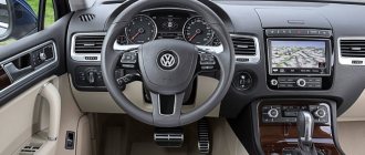
- under plastic plugs on the bottom of the instrument panel or on the center console (typical for VAG products);
- on the rear wall of the instrument panel behind the glove box body (some Lada models);
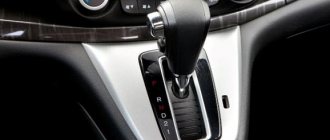
- on the center console in the area of the parking brake lever (found on some GM cars, in particular Opel);
- in the lower part of the armrest niche (common on French cars);
- under the hood near the engine shield (typical of some Korean and Japanese cars).
When searching for a connector on used cars, you should take into account the possibility of repairs to the electrical wiring, as a result of which the block may be moved to a non-standard location.
Various options for installing the OBD 2 connector are shown in the photo below.
Connector in the mounting block in the instrument panel on Hyundai Santa Fe
Connector in the glove box on Renault Sandero
Connector on the center console on Lada Kalina
Connector under the side console cover on a Honda Civic