Other symptoms of a faulty mass air flow sensor:
1)Check Engine error appears; 2) Increased fuel consumption; 3) Poor starting when hot; 4) The car began to accelerate slowly; 5) Engine power lost. 6) Etc.
How to check the mass air flow sensor
Method No. 1: Disable the mass air flow sensor.
Disconnect the sensor connector and start the engine. If you turn off the MVR, the controller switches to emergency mode and prepares the fuel mixture only according to the throttle position. Engine speed must be greater than 1500 rpm. Let's try to go for a ride. If the car feels “faster”, then we can say that the mass air flow sensor is not working. By the way, for ECU Y7.2, M7.9.7. The speed does not increase when the chip is turned off!
Method No. 2: Alternative ECU firmware.
If the standard firmware of the controller was replaced with another, then it is unknown what is built into it in case of emergency mode in method No. 1. Try sliding a 1mm thick plate under the damper stop. The revs will rise. Pull out the chip from the mass air flow sensor. If it doesn’t stall, it means the problem is with the firmware, or rather with the IAC steps in emergency mode without a mass air flow sensor.
Method No. 3: Checking the mass air flow sensor with a multimeter.
This method works on Bosch sensors with catalog numbers: 0 280 218 004, 0 280 218 037, 0 280 218 116. Turn on the tester in the DC voltage measurement mode, set the measurement limit to 2 Volts.
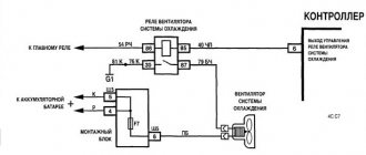
MAF pinout: 1) Yellow (closest to the windshield) - MAF signal input; 2)Gray-white—sensor supply voltage output; 3) Green - sensor grounding output; 4) Pink-black - to the main relay. Wire colors may change, but the pin layout remains the same. Wire colors may change, but the pin layout remains the same.
We turn on the ignition, but do not start the engine. We connect the multimeter with the red probe to the yellow mass flow sensor, and the black one to the green one (to ground). Thus, we measure the voltage between the specified terminals. The tester probes allow you to penetrate through the rubber seals of the connector, along the specified wires, without disturbing their insulation.
The use of needles and other additional connections is not recommended, because they introduce some error in measurements
. We take readings from the multimeter. The output voltage of the new sensor is 0.996…1.01 Volts. During operation, it gradually changes and, as a rule, increases. The greater the value of this voltage, the greater the wear of the mass air flow sensor.
Mass air flow sensor voltage: 1.01…1.02 - good condition of the sensor. 1.02...1.03 - not a bad condition. 1.03…1.04 - the life of the mass air flow sensor is coming to an end. 1.04...1.05 - a dying state, if there are no negative symptoms, then we continue to exploit it. 1.05...and higher - it’s time to replace the mass air flow sensor.
By the way, the same readings can be obtained without a tester, using the on-board computer (group of parameters “voltage from sensors”, Udmrv)
What is your MAF sensor? The first mass air flow sensor was a frequency sensor in the control system from GM. It was also used in “January” of the 4th series. Cars of this configuration did not last long and the frequency sensor was replaced by an analog model HFM-5 from Bosch under number 0280218004.
It is not interchangeable with GM; the connectors and mounting points are completely different. The German sensor is dismountable and consists of two parts - a housing and a measuring element. The latter is secured in the case with two screws with “secret” heads.
Bosch only sells assembled sensors in yellow cardboard packaging.
The third version of the mass air flow sensor is 0 280 218 037 or 037th, as determined by car enthusiasts by the last three digits in their designation. This is a further development of the 004 sensor from Bosch.
Such a sensor is used today on most VAZ cars, including Niva and Chevrolet Niva. Externally, 004 and 037 are almost indistinguishable; you need to navigate by their numbers.
Recently, additional markings have appeared on products: now there are numbers on both the body and the measuring element - they must match.
The main difference is inside the mass air flow sensor. The 037th sensor has a different design of the measuring element, with a characteristic cutout (when purchasing, it makes sense to remove the plug and look inside).
Then a new control system appeared - Bosch M7.9.7, which has its own, 116th mass air flow sensor. It is not interchangeable with the previous ones, although its body is the same.
To avoid confusion, a green circle was first applied to the body. There are numbers on both the body and the measuring element. The latter determines the purpose of this mass air flow sensor.
VAZ 2110 air sensor pinout diagram
- Yellow (closest to the windshield) - mass air flow sensor signal input;
- Gray-white—sensor supply voltage output;
- Green — sensor grounding output;
- Pink-black - to the main relay.
The wire colors may change, but the pin locations remain the same.
Let’s also add that the mass air flow sensor with endings 004, 037, 116 (for Bosch) and 00, 10, 20 (for Pekar) are different in calibration. You can only change it by flashing it.
Mass air flow sensor table. VAZ DMRV engines. Last three digits
But to implement them, it is necessary that the sensors informing the controller do not deceive it - only under this condition do the processes in the cylinders proceed normally, the engine develops sufficient power without consuming excess fuel and without causing much harm to the environment. One of these sensors measures the amount of air entering the cylinders and generates a corresponding signal to the controller. This can be an absolute pressure sensor (MAP sensor) or a mass air flow sensor (MAF). We see the latter on many cars, including VAZ ones.
The first was the frequency mass air flow sensor of the GM control system. It was also used in the domestic analogue “January” of the 4th series (photo 1). Cars of this configuration did not last long on the assembly line - the frequency sensor was replaced by an analog model HFM-5 from Bosch - its number is 0280218004 (photo 2). It is not interchangeable with GM - the connectors and mounting points are different. The German sensor is dismountable, consisting of two parts - a housing and a measuring element.
The latter is secured in the case with two screws with “secret” heads. True, nowadays you can buy the necessary tools in auto parts stores. The measuring element is a compact thing, but it is expensive - in Moscow from 1300 rubles. and higher. Having removed this part from a new car, in exchange, of course, they will put a dummy, and everything that follows is the “personal grief” of the car buyer. The market is full of such “mass air flow sensors without a housing”... It is unwise to buy a measuring element without a housing: it is very possible that it is faulty or the wrong model. Bosch only sells assembled sensors in traditional yellow cardboard packaging. Let us remind you that the store may not accept a return air flow sensor purchased from the “wrong system” if the motorist does not provide a certificate from the service, and it is often difficult to obtain one. An unnecessary expensive unit will remain as a keepsake.
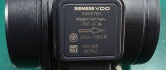
The third version of the mass air flow sensor is 037. (Here we are talking about the last three digits in the designation.) This is a further development of the 004th sensor from Bosch. Such a sensor is used today on most VAZ cars traveling on the roads, including Niva and Chevrolet Niva. Externally, 004 and 037 are almost indistinguishable - just look at the number (photo 3). Recently, additional markings have appeared on products: now there are numbers on both the body and the measuring element - they must match. The main difference is inside the mass air flow sensor. In photo 4 on the right is the 037th sensor. It has a different design of the measuring element, with a characteristic cutout (when purchasing, it makes sense to remove the plug and look inside).
Connecting the MAF air sensor VAZ 2112
If the mass air flow sensor is operational, then when the engine is running at 900 rpm, the volume of air used will be at least 10 kg per hour. When the speed increases to 2 thousand, this figure will increase to approximately 20 kg. If the volume of air at such speeds drops, the dynamics of the vehicle will also decrease, and accordingly, this will lead to a decrease in gasoline consumption.
If these indicators increase, this will also contribute to an increase in fuel volume. Deviations of the parameter by 2-3 kg should not be allowed, since in this case the operation of the power unit may be incorrect.
Where is the DMRV located?
The sensor is located between the air filter and the air supply hose (pictured No. 13).
Catalog numbers of mass air flow sensor on LADA cars:
- Lada Priora, Kalina and Niva 4x4 – 21083-1130010-20.
- Lada Granta and Kalina 2 – 11180-1130010-00.
- Lada Vesta, Largus and XRAY - no mass air flow sensor. Modern VAZ engines (21127, 21129, 21179) and Renault engines (K7M and K4M) do not have a mass air flow sensor; instead, an absolute pressure sensor (APS) and an air temperature sensor (ATS) are installed.
Connection diagram for air flow sensor 2114
A common cause of incorrect operation of the mass air flow sensor is the failure of electronic components, which increases the sensor’s response time to changes in air flow. A working sensor monitors changes at a speed of 0.5 ms, and if it breaks down, the response time increases by 20-30 times. The defect is detected only by recording the operation graph with an oscilloscope. Such a sensor cannot be repaired; it must be replaced with a new one.
VAZ 2114 signs of flow meter malfunction
In addition to the indicator light on the Check Engine, there are symptoms that even an inexperienced driver will notice:
- Unstable engine operation at idle speed: the malfunction manifests itself most clearly when the engine is not warmed up. After starting, the revs fluctuate, and when the accelerator pedal is pressed sharply, the engine stalls.
- With a sharp release of gas, the speed does not decrease, but remains at around 2-3 thousand for some time.
- Even with a warm engine, there is a noticeable decrease in power. When fully loaded, a lower gear is required; the car does not pull uphill and accelerates slowly on the highway.
Replacing the sensor - instructions
Using a screwdriver, unscrew the clamp of the air intake corrugation at the sensor outlet, pull it off and carefully inspect the internal surfaces of the sensor itself and the corrugation. These surfaces must be dry and clean; traces of condensation and oil are unacceptable. If the air filter is changed rarely, then dirt getting on the sensitive element of the sensor is the most common cause of its breakdown in VAZ cars.
There may be oil in the mass air flow sensor as a result of an increased oil level in the engine crankcase, or the oil sump of the crankcase ventilation system is clogged.
Next, unscrew the 2 screws of the sensor with a 10mm wrench and remove it from the air filter housing. There should be a rubber sealing ring on its front part (at the entrance edge). It prevents unfiltered air from being sucked into the intake tract through the sensor.
If the ring is out of place and stuck somewhere in the air filter housing, then there will be a thin layer of dust on the inlet mesh of the sensor itself. This is the second reason that destroys the mass air flow sensor ahead of time.
Correct assembly should take place in the following sequence: put a sealing rubber band on the sensor, check the sealing skirt, then insert everything together into the filter housing.
This concludes the visual check of the mass air flow sensor at home. You can check its operation 100% only with the help of special equipment in a car service center. For example, using a technique for assessing the oscillogram when the throttle is sharply opened to the cutoff mode (a motor tester is needed), or assessing the oscillogram when the ignition is turned on.
Resuscitation of a damaged air flow sensor is successful in no more than 5% of cases. In extreme cases, you can rinse with ethereal liquid to clean matrices and optics. It will evaporate without a trace. After making sure that there is no more dust or debris in the device, you can dry it thoroughly and put it back in place. Sometimes after such a simple procedure the device will work.
On most foreign cars, a mass air flow sensor was installed until 2000; subsequent generations of models began to be equipped with a pressure controller. Replacing a non-working sensor is simple and can be done on your own without any problems, you just need to buy a mass air flow sensor that matches the ECU firmware version. Its price is around 3,000 rubles, depending on the manufacturer.
How to check the serviceability of the mass air flow sensor
First of all, you need to regularly carry out computer diagnostics of your car, even in a garage, using basic car scanners. Any version of the Gazelle car is equipped with an OBD-II port, with which you can obtain detailed information about the operation of the engine’s electronic systems.
The initial parameters of the air flow sensor (we first select the model and type of engine on your car) are programmed into the diagnostic program. So a deviation from the norm will be recorded, and advanced programs will also suggest the probable cause of the breakdown.
However, there is a more primitive method that you can use if you don’t have a diagnostic scanner at hand. Every car enthusiast has a digital multimeter in their garage. The main thing is that its error is low: the voltage readings at the information contact of the mass air flow sensor vary within hundredths of a volt, and it is precisely this minimum range of values that the ECU is designed for.
The illustration shows the pinout of a sensor from Siemens, or its Russian analogues Avtel and Elkar.
- First of all, we check the integrity of the wiring harness and cable contact group. To do this (having first disconnected the negative terminal of the battery), disconnect the connector and connect the battery back. Turn on the ignition without turning the starter. There should be 12 volts on pin #2. Not 13.5, as on the battery, but precisely 12, after the voltage regulator. At pin No. 4 the sensor is supplied with 5 volts.
- Then we connect the connector back (remembering to temporarily disconnect the battery ground). We check the most important sensor signal: thermistor compensation voltage. With the ignition on, this value should be in the range of 0.99 - 1.02 volts. 1.03 - 1.05 volts are allowed, but such a mass air flow sensor will not last long. Any other value, even with a tolerance of 0.01 volts from the nominal value, indicates a breakdown.
The second way is using a multimeter
Before performing these diagnostics, it should be noted that this will only work with a Bosch mass air flow sensor. Before performing the test, set the limit on your multimeter to 2 V, and then switch the device to constant voltage operation.
Turn on the ignition and connect the red wire to the yellow one on the block. Connect the black wire to the green one. At this moment the engine should not be running. Measure the voltage If the reading is between 1.01 and 1.02 then everything is fine. The multimeter shows voltage up to 1.03 - there is nothing to worry about, this is acceptable. The limit level is 1.05. If it is higher, then you can again look for the cause of the breakdown.
Mass air flow sensor device (English abbreviation - MAF)
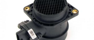
- The housing is made in the form of a cylinder, the diameter of which coincides with the air duct of the intake manifold. Installed at the outlet of the air filter (using the example of a VAZ 2112). The housing itself is a calibrated measuring channel.
- To protect against foreign objects, a deflector and a metal screen in the form of a mesh are installed at the entrance. The correct air flow is formed through them.
- The air flows through the flow sensor itself, which operates on the thermal anemometric principle. There are two resistors installed inside (reference and variable), connected to a common circuit using a ballast circuit. Variable, precision, changes resistance when cooling and heating. The thread of this resistor is made of an alloy of iridium and platinum. The control board monitors that the resistance is the same. To do this, a platinum thread cooled by an air flow is heated by electric current. The resistor is constantly supplied with voltage, the value of which varies with an accuracy of 1/1000 volt.
- The value of this voltage is output by the MAF circuit to pin No. 5 of the connector. The signal is read by the ECU controller and programmatically converts this value into air mass (kg/hour).
Diagnosis of device malfunctions
Determining a problem with the mass air flow sensor is not so easy. Many symptoms of failure of this sensor coincide with signs of failure of other components and assemblies of the car. Typical symptoms of problems with the mass air flow sensor are cases when:
- the engine noticeably loses power;
- there are failures when pressing the accelerator;
- fuel consumption increases significantly;
- Starting a warm engine becomes more difficult.
When the mass air flow sensor fails, the Check Engine light on the dashboard lights up. But it turns on not only when the mass air flow sensor fails. And it’s not at all easy to figure out what kind of breakdown the indicator is signaling in this case, so it’s better to turn to professionals for diagnostics.
Cases when the average car enthusiast can figure it out on his own are relatively rare. These include a situation when you suspect a failure of the mass air flow sensor, and your friend has the same “nine” as yours with a perfectly working engine. Borrow a known-good air flow sensor from a friend for one hour. Remove your sensor, install a good one, and go for a ride. If the problems disappear, go to the store for a flow meter: the problem is that the mass air flow sensor is broken.
DMRV Siemens vdo 5WK97014 from VAZ 2104-2107 to VAZ 2110-2112 — Lada 2112, 1.6 l., 2006 on DRIVE2
I don’t know how to paint it beautifully, and I’m too lazy))) relevant for January, Siemens is notable for its price of 1900-2300 rubles and long service life, and there is no need to be tricky with attaching the air filter to the housing (in the classics there is a housing 2112))) as when installing a DMRV from gas. I chose the MAF from the Continental company. I had to smoke classic forums for a very long time))) I’ll write it down in parts (a link to the next part where the calibration implementation will be implemented and links to ready-made files will be at the end)
for installation in the software, you need to change the MAF calibrations in the native firmware (details will be in the next part) and to re-cross the wiring, you definitely need a Siemens MAF connector. Pinout: Bosch1 (DTV) 2 (+12V) 3 (ground) 4 (+5V from the ECU)
Siemens classic1-(+12v)2-(+5v from ECU)3-(signal)4-(DTV)5-(ground)
If the DMRV does not have DTV (4 wires go to the Bosch connector), then we connect according to the same scheme, ignoring the points with DTV.
The adapter is still rough. Later I’ll fill it with a heat gun or I’ll make it directly without an adapter. I soldered the adapter (from a dead MAF, grinding it down to the contacts), because I wasn’t sure that my topic would work. You can do without it: we pull out the wires from the Siemens connector (there are connectors with a double-sided clamp, you need to clamp it on both sides) and having pulled out the wires from the original plug (it’s easier to pull it out. The clamp is on one side), we stick it into the Siemens connector, observing the pinout. They fit like family.
ADDENDUM: it is very difficult to pull out the contacts from the original plug in the wiring. There is a lock on both sides)))
Issue price: 2,300 ₽
Preventive repair of mass air flow sensor
A broken flow meter cannot be repaired. The exception is cases of contamination of the sensor, which impairs its performance. In these cases, preventive repair of the air flow sensor can be carried out. The VAZ 2109 has a special self-cleaning mechanism for the platinum string of the flow meter: it is periodically heated to a temperature above 1000 degrees. Timely replacement of the air filter also helps keep the sensor element clean.
It is known that the mechanism cannot be damaged by cleaning.
| Main stages | Your actions |
| Before dismantling the mass air flow sensor, do not forget to de-energize the system. | Disconnect the six-pin wiring harness from the sensor. Loosen the clamp and disconnect the air filter pipe. Using a 10mm wrench, unscrew the bolts securing the flow meter to the air filter housing. |
| Carefully remove the sensor. | From a distance of 12–15 centimeters, generously spray a special carburetor cleaning spray from an aerosol can. Be careful to avoid getting the spray on your skin - it is very caustic. |
| Let the spray flow and dry. | If necessary, repeat the procedure two or three more times. |
| Mount the flow meter in reverse order. | Take a ride. If the problem persists, remove the electrical connector from the sensor. |
The controller will go into standby mode, increase idle speed and increase fuel consumption, but will ensure uninterrupted engine operation. Next, let the professionals deal with your problem: take a course at a proven car service center.
Source
Checking and repairing at home
There are eight ways to independently check amplitude and frequency mass flow sensors.
Method No. 1 - disabling the air flow meter
The method consists of disconnecting the sensor from the fuel system of the car and checking the functionality of the system without it. To do this, you need to disconnect the device from the connector and start the engine. Without a mass air flow sensor, the controller receives a signal to switch to emergency operation mode. It prepares the air-fuel mixture only based on the throttle position. If the car moves faster and does not stall, it means that the device is faulty and requires repair or replacement.
Method No. 2 - flashing the electronic control unit
If the standard firmware has been changed, then it is unknown what reaction of the controller is programmed in it in case of an emergency. In this case, you should try to insert a 1mm thick plate under the throttle stop. The turnover should increase. Now you need to pull out the chip from the air flow meter. If the power unit continues to work, then the cause of the malfunction is the firmware.
Method No. 3 - installing a working sensor
Install a known good part and start the engine. If after replacement it begins to work better, the motor does not stall, then replacement or repair of the device is required.
Method No. 4 - visual inspection
To do this, use a Phillips screwdriver to unscrew the clamp holding the air collector corrugation. Then you need to disconnect the corrugation and inspect the internal surfaces of the air collector corrugation and the sensor.

