The throttle sensor is used to meter fuel.
That is, based on the amount of air passing through it, it provides the control unit with information - how much gasoline is needed to form a combustible mixture.
As well as determining the engine operating mode: idling, acceleration and constant speed.
Purpose and types of TPS
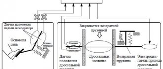
The throttle position sensor generates an electrical signal corresponding to the opening angle of the air damper. The readings are necessary for the correct operation of the controller (ECU). This signal, together with data from other sensors, is used by the controller when generating fuel injection and sparking pulses.
Regardless of the design, the TPS can be thought of as a potentiometer: one terminal of which is connected to ground, and the other to the on-board power supply. The voltage corresponding to the position of the damper is removed from a terminal similar to a moving contact.
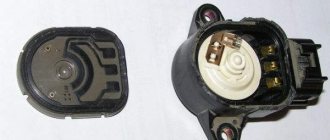
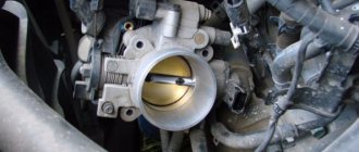
It is installed on the throttle body on the side opposite the air damper drive. Its moving element is mechanically connected to the damper axis.
- film resistive. It is a regular potentiometer. Their service life reaches 50 thousand km;
- non-contact (magnetoresistive). The operating principle is based on the Hall effect. Failure-free operation time depends only on the quality of the mechanical part of the device. A device of this type is, of course, much more expensive than film-resistive ones.
Symptoms of malfunction
Checking the throttle position sensor is necessary in the following cases:
- deterioration in acceleration dynamics.
- increased, decreased, or unstable crankshaft speed at idle.
- jerking when driving on a flat road with constant pressure on the accelerator pedal.
- stopping the engine in neutral.
- stopping the engine while changing gears.
- the engine does not develop maximum power.
Causes of malfunctions
- The main reasons for the failure of film-resistive TPS are mechanical wear of the resistive layer and the potentiometer slide, as well as dirt getting on the working surface.
- Magnetoresistive ones also have two causes of failure: failure of the moving unit and failure of the electronic converter of magnetic signals to direct voltage.
Checking the idle air control (IAC) of the Chevrolet Lacetti
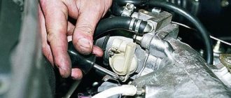
Now let's focus on checking the idle air regulator, i.e. on an electric motor in the throttle assembly. It can also be checked.
To check the wiring, brushes and motor windings, you need to connect the ohmmeter probes to the 61st and 62nd pins of the ECU block
The ohmmeter reading should be 2-5 ohms
In my case, the readings were 4.4 Ohms (1 Ohm is the resistance of the probes themselves). If the resistance goes beyond these limits, then it is necessary to separately ring two power wires of the IAC motor - from the 61st contact of the ECU block to the 1st contact of the throttle block block and from the 62nd contact of the ECU block to the 5th contact of the throttle block block.
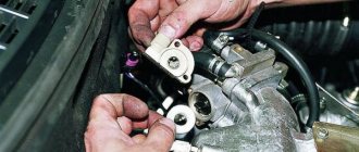
If the wires do not raise any questions, then it is necessary to disassemble the throttle assembly.
As you can see, checking the TPS and conducting a general analysis of the throttle assembly and its wiring is not at all difficult. Without even removing it from the car. The main thing is to understand the meaning of actions.
Checking TPS
Checking the throttle position sensor using the example of a VAZ 2110. Preliminary actions:
- Close the throttle valve.
- Turn on the ignition.
- Use a voltmeter to check the voltage at the output of the device. It should be no more than 0.7 V. Its output is determined very simply - two wires for ground and power, and the third, respectively, for the output.
- Measure the voltage at the output with the damper fully open. It must be at least 4 V.
- Check the change in output voltage when the damper opens and closes. The voltage should change smoothly, without surges.
- If the results of your measurements coincide with those described above, then your sensor is working. If anything is different, you need to buy a working one.
The failure of this sensor is recorded in the controller's memory. In such cases, the “check engine” sign usually starts to light up.
The engine is put into emergency operation mode, intended only to get to the auto repair shop under its own power, which further increases the discomfort when driving and also increases fuel consumption.
Replacing the sensor
Location of the TPS using the example of the VAZ 2110
Replacing the TPS does not require disconnecting the battery, since it is de-energized when the ignition is turned off. So just turn off the ignition. Gently pressing the stopper, remove the connector from the sensor. Unscrew the screws securing the sensor and remove it. When installing a new sensor, first carefully align the end of the damper shaft with the seat. After this, by rotating the sensor, align the holes in the sensor with the holes in the damper body. Screw in the fastener and tighten it. Don't forget to put the connector on. All that remains is to erase the error from the controller’s memory.
You can try to erase the error from your memory yourself by disconnecting the terminal from the battery overnight. If the attempt to delete the error code is unsuccessful, there are two options left: go for diagnostics and remove it with a motor tester, or wait until the controller itself removes it.
Adjustment
The TPS of VAZ family vehicles does not require adjustment. On cars for which its adjustment is provided, it is done as follows: after installing the new sensor, completely close the air damper by turning it by the drive, if it is mechanical. Or remove the air duct and press on its edge if it has an electric drive. Then connect the voltmeter probes to the sensor output and to the vehicle ground, strictly observing the polarity. Turn the sensor so that the voltmeter shows the minimum voltage for this sensor (ideally 0 V). Then tighten the fasteners. If, after adjustment, the idle speed is higher than it should be, it means that on your car you need to carry out a procedure for training the controller with the parameters of the new TPS. To do this you should:
- Disconnect the battery terminal for 15 minutes.
- make sure the throttle valve is closed.
- turn on the ignition for a few seconds without starting the engine.
- turn off the ignition.
- wait about 15 seconds. At this time, the controller will write into its memory new parameters of the TPS that replaced it, which has become unusable.
The throttle valve in a car is a structural unit that is part of the intake system on gasoline power units. If a malfunction occurs in the mechanism, you need to check the throttle position sensor. To do this, you can use one of the methods.
How to check?
You can check the serviceability of the sensor using 3 devices:
- diagnostic scanner;
- motor tester;
- multimeter.
Checking with a diagnostic scanner
We connect the scanner to the car and find the parameters in the program. In the parameters we find the throttle sensor readings. The scanner can display data from the sensor, both in volts and as a percentage. If in volts, then we look at the values within 5 V.
IMPORTANT! The scanner will display values from 0.3 to 4.7. This is done so that the control unit understands that the sensor is working. If there is “0” volts, then an error will appear - “sensor break”. If “5” volts, the damper is completely open or there is a short circuit.
If in percentage, then we look at the percentage of the damper opening from 0 to 100%. If everything is in order, then on the scanner when the damper is opened we will see percentages: 0%, 2%, 3%, etc.
If we see the values: 0%, 20%, 0%, 15%, 3%, 4%, 20%, etc. - this indicates wear of the resistive layer.
Checking the throttle sensor using the Launch scanner as a percentage. On the left are digital values, on the left in graphical form.
Motortester
To check the throttle sensor with a motor tester, you need to connect to the signal wire of the sensor and to the negative wire. Then we begin to open the damper. What should we see? If everything is good, then we will see the following waveform:
Oscillogram of a working sensor
If the resistive track is worn out, then the oscillogram will look like this:
Oscillogram of a faulty sensor
Noise at the beginning of the resistive trace is the first sign of wear.
Multimeter
When checking the throttle sensor with a multimeter, check the voltage between the positive and negative wires. The engine must be running at the same time. The measurement values should be about 5 volts.
The next step is to measure the resistance between the sensor signal wire and the negative wire. In this case, the ignition is turned off completely, and the multimeter is set to measure resistance.
In the closed position of the throttle valve, the multimeter should display values from 0.8 to 1.2 kOhm, and in the open position from 2.3 to 2.7 kOhm.
Characteristics of the throttle position sensor
The purpose of the sensor is to regulate the volume of air flow that enters the motor. This air is used to form a flammable mixture.
Where is the sensor located in the car?
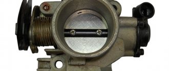
In order to diagnose the device if necessary, the car owner needs to know where the TPS is located. The controller is installed in the engine compartment. It can be seen on the side of the throttle line on the axis of the valve itself.
Controller location on the throttle
Device design
Structurally, the device includes the following:
- Controller housing. This component is made of heat-resistant fiberglass. The housing is equipped with two flanges, which are used to secure the controller to the throttle assembly.
- A connecting device equipped with three contacts. This component is integrated with the controller housing.
- A resistive device made of ceramic.
- Current collecting element. This component is designed to provide electrical contact with the resistive part.
- Collet clamp, equipped with a slot.
- Rubber gasket. Used to mount the controller on the axis of the throttle assembly.
Device
This component of the system is a fairly simple electrical resistor, which changes the resistance when the axis is rotated.
The sensor is located on the damper shaft and, when it opens, performs the function of turning together with the damper. Due to the fact that the design is quite primitive and unreliable, the sensor often fails, resulting in certain problems with the formation of the fuel mixture. So, in most cases, the problem is the rubbing of the tracks, but the possibility of other problems with the condition of the resistor cannot be ruled out.
Symptoms of sensor failure
The main signs that can help identify problems in the operation of the TPS controller:
- Difficulties arise in the operation of the power unit at idle. The speed is unstable, it can sharply increase or decrease without the driver pressing the gas pedal.
- The power unit may stall when the driver changes gear from one mode to another. Arbitrary stopping of the engine is possible both when driving at neutral speed and when parking, for example, at a traffic light or in a traffic jam.
- Gasoline consumption increases significantly. Sometimes the increase in fuel consumption is invisible to the car owner. Then the overexpenditure can only be determined by measurement.
- Instability in idle speed is detected. Moreover, this does not depend on the operating mode of the power unit.
- The engine power of the car drops significantly. Its reduction can usually be clearly noticed when driving on an incline, when a higher gear is engaged. By switching to a lower speed, you can avoid a drop in traction.
- If the vehicle is accelerating or moving at low speeds, you may feel a jerking sensation when you press the gas.
- The engine stalls as soon as the driver releases the gas pedal.
- Popping sounds begin to be heard from the intake manifold. They appear periodically and can sometimes be heard when you press the gas.
- The Check Engine light appears on the instrument panel. It can light up constantly or light up periodically.
Ivan Vasilyevich spoke in detail in practice about the symptoms of TPS malfunctions.
Replacing a spare part
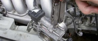
DPDZ ZMZ 406 is located on the side of the throttle pipe. When replacing, remove the contact connector of the ECU cable. Use a Phillips screwdriver to unscrew the mounting bolts and remove the device. The new sensor is installed in the reverse order.
You should only purchase a new sensor from trusted suppliers. It is risky to buy cheap devices, as this can result in unexpected troubles on the road when you have to barely trudge along the highway in search of the nearest service station.
Mikas is a comprehensive car engine control system. Similar to the January system. The system includes: a set of sensors (input periphery), an electronic control unit (ECU), a set of actuators (output periphery) and a wiring harness with connectors (performs the functions of a simple interface)*. The system can use components of both domestic production and Bosch. There are 5 main modifications in total: 5.4, 7.1, 10.3, 11 and 12.3 versions.
Car engine diagnostics begins with reading error codes from the controller's RAM. Checking the wiring is quite simple if you have a Mikas pinout (pin assignment) of the controller connector and a multimeter. As a last resort, you can use a control llama, but this is not entirely convenient. Next comes the pinout of the connectors of this ECU of various modifications:
The control unit is installed on GAZ vehicles in the passenger compartment on the front panel on the passenger side. The unit is connected to the wiring harness using a 55-pin socket with a latch. When connecting the harness socket to the unit, you must be careful and do not apply much force so as not to “crumple” the pins of the control unit plug. After installing (replacing) the unit, it is recommended to perform a CO adjustment at idle speed.
Types and versions of MIKAS-5.4 blocks
- 201.3763—for GAZ-3129, GAZ-3110 cars and for GAZ minibuses with a ZMZ-4062.10 engine with a synchrodisc.
- 207.3763—for GAZ-3129, GAZ-3110 cars and for GAZ minibuses with a ZMZ-4062.10 engine with a synchronization flywheel.
- 209.3763—for GAZelle cars and GAZ minibuses with ZMZ-4063.10 and ZMZ-4061.10 engines with a synchrodisc.
- 2012.3763—for GAZelle cars and GAZ minibuses with ZMZ-4063.10 and ZMZ-4061.10 engines with a synchronization flywheel.
Causes of malfunctions
Reasons why repair or replacement of the TPS may be required:
- The contact elements have become acidic. This problem can hardly be called a breakdown, but it refers to malfunctions that can be eliminated. During prolonged use, the sensor contacts may oxidize. This is due to the operation of the TPS under conditions of temperature changes and exposure to moisture. To eliminate the problem, you need to dismantle the controller and clean the contact elements with cotton wool treated with WD-40.
- Erasing the coating based on the initial segment of the slider movement. If the resistive base is removed, the controller will not operate correctly. As the slider moves, the voltage supplied to the control module will increase. But as a result of erasing, this does not happen, since there is no resistance. This leads to problems, and sometimes the control module malfunctions.
- Damage to the tips on the device. If this happens, burrs will form on the lining, which will ultimately lead to failure of the remaining elements. In some cases, the contacts will continue to function, but this will not last long, especially since the wear on the substrate will increase. With such problems, the slider and the resistive layer will refuse to contact, which will lead to the inoperability of the machine’s motor.
- Slider failure. This component of the device wears out over long-term use. As a result, it may deviate from the required trajectory, which will lead to problems.
One of the reasons for the failure of the throttle position controller is shown in the video of the “Everything Yourself” channel.
In lamps
In luminaires designed for the use of fluorescent lamps, in addition to the lamps themselves, components such as a starter and a choke are used.
The starter, as the name suggests, starts the glow process in the lamp and does not participate further in the process. The choke functions as a current and voltage stabilizer during the entire period of the lamp's glow.
If the choke is faulty, the lamp does not light or does not burn steadily, its glow is not uniform along its entire length, and areas with a brighter glow may appear inside, moving from one electrode of the lamp to another. Sometimes you can notice the flickering effect of the light.
If the throttle is faulty, the lamp may not light up the first time, and the starter will turn on repeatedly until the lighting process finally starts. As a result, dark spots will appear on the lamp bulb where the spirals are installed. This is due to the fact that the coils operate for a longer time than is set for normal starting.
How to replace the throttle position sensor?
Replacing the controller is done like this:
- The car's ignition is deactivated. It is not necessary to disconnect the battery, since the device is de-energized.
- The engine compartment is opened, the connector is disconnected from the controller and the bolts that secure it are unscrewed. There are usually two fixing screws, but the number may vary depending on the device and machine model.
- The failed TPS is dismantled. The contacts to which it is connected are cleaned with a brush.
- A new controller is being installed. When installing, you must carefully connect the end part of the damper axis to the installation location of the device.
- The controller then scrolls in a circle. This is important to do in order to align the holes and secure the bolts that secure it. After tightening the screws, a block with wires is installed on the sensor.
How to adjust the throttle position sensor?
After replacing the throttle position sensor, it is adjusted, this will ensure proper operation of the TPS.
You need to adjust the new controller like this:
- The corrugated line connected to the inlet manifold device is dismantled. After disconnection, a visual diagnosis of the condition of the damper itself is performed. It is necessary to wipe this element, as well as the intake manifold, using a rag soaked in fuel.
- Then the damper thrust bolt is released. The element itself opens all the way and is sharply released; when this task is completed, a click should be heard when it hits the stop.
- The tension of the thrust bolt is adjusted; in the process, you need to click the damper. When this component stops “biting” and moves freely, the screw must be secured with a nut.
- Then the bolts that secure the controller are loosened. One tester probe is connected to the idle speed contact element, and the second is connected between the thrust bolt and the damper itself. The controller body is rotated until the voltage parameter begins to change with the opening of the damper.
- When this happens, the bolts can be secured.
Dmitry Maznitsyn spoke in detail about the procedure for adjusting the throttle position controller using the Volkswagen Passat as an example.
What should I do if I have problems with idle speed after adjusting the sensor?
If adjusting the throttle position sensor led to jumps in idle speed, you need to perform a procedure to familiarize the electronic unit with the characteristics of the new TPS.
The task is performed like this:
- The terminals from the battery are disconnected. The clamps are loosened with a wrench, after which you need to wait about 20 minutes.
- Then the terminals are connected back. Before the next step, you need to make sure that the valve of the unit is closed.
- The key is inserted into the lock and the ignition is activated for approximately 15 seconds. The power unit does not start. After this, the ignition is turned off.
- Then you need to wait about 20 more seconds. During this time, the microprocessor module will be able to remember the characteristics of the new TPS in its memory.
Pinout Mikas 7.1 injector and carburetor
This block is designed to control internal combustion engines:
- ZMZ-4062.10—with gasoline injection and electronic control;
- ZMZ-409.10—with gasoline injection and electronic control;
- ZMZ-405.10—with gasoline injection and electronic control;
- ZMZ-4063.10—carburetor, with electronic ignition system;
- ZMZ-4061.10—carburetor, with electronic ignition system.
- UMZ-4213.10—with gasoline injection and electronic control;
- UMZ-420.10—with gasoline injection and electronic control.
The block is a multi-mode cyclic machine with an extensive program that provides registration and processing of information from the system sensors to control the actuating electric mechanisms of the engine. The block is implemented on the basis of an 8-bit microcontroller and on an imported element base, has a monoblock single-board design with a 55-pin electrical connector from AMP.
Types and versions of MIKAS-7 blocks
- "MIKAS-7.1"—for GAZ cars;
- "MIKAS-7.2"—for UAZ cars.
Designation of the MIKAS-7 block according to TU: 29ХK.3763-YY, where:
- X—even number for the block version with an immobilizer, odd number—without an immobilizer;
- X—number 1 or 2—for UMZ-XX engines;
- X—number 3 or 4—for ZMZ-XX engines;
- K—climatic version: k=7 for version “U-T”, no number for version “U”;
- YY—version number according to purpose: engine brand, control system configuration, vehicle type.
For example, the MIKAS-7.2 block has the following versions:
291.3763000-01—for UAZ-31625 with UMZ-4213.10 engine; 293.3763000-01—for UAZ-3159 with ZMZ-409.10 engine.
Table of pin number and what it is connected to
Video “Procedure for adjusting TPS”
The Resta channel has provided a detailed guide on how to perform the procedure for adjusting the controller after replacing it.
In modern cars equipped with advanced electronics, sometimes one small part can block the operation of all systems. Such an element can be a throttle position sensor (TPS).
Location
The location of the sensor is quite accessible - on the base of the throttle body, which is located above the cold speed sensor. It is worth noting that in most cases this resistor is fixed with two screws that can be unscrewed with a Phillips screwdriver, and there is also a certain foam washer and boot.
Why was the throttle valve equipped with a sensor?
The injector is equipped with flaps that change the angle of location, opening/closing the gap for the passage of air flow. Its volume should be enough to create a mixture with fuel in optimal proportions (ideally 14.7 parts of air per 1 part of gasoline). The mixture is then injected in portions into the engine cylinders, where it is burned.
In order to successfully regulate all stages of fuel supply (and this is a huge number of parameters), the electronic unit needs a reliable assistant who will collect and send truthful and timely information to the central authority.
Such functions are assigned to a miniature device - the PDZ sensor, the trouble-free operation of which determines the proper and efficient functioning of the engine.
The data from this sensor forms the basis for the calculation parameters for many electronic systems controlled by the ECU:
Principle of operation
TPS of the ZMZ 406 engine is a mechanical device. The coaxial connection of the two-contact slider with the throttle valve ensures timely movement of the contactor along the two-way resistive track. The angle of rotation of the damper changes the resistance of the metal tracks through which a weak current passes along the cable to the ECU. In accordance with changes in the current characteristic, the ECU issues commands that bring the power system to the optimal operating mode.
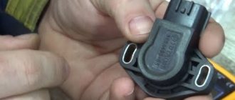
The pinout of the DPDZ ZMZ 406 for the Gazelle or Volga consists of a three-pin connector of the ECU cable, where the first contact supplies current to the device slider, the second is “0”, and the third removes voltage from the two-channel resistive track.
How does the remote sensing position sensor work?
Most manufacturers equip cars with moving (contact) sensors, which are ponetiometers with a moving element. This is its weak point, because it experiences friction, which leads to rapid wear. Now there is an active transition to a contactless option. It has great operational potential and high accuracy of parameter measurement.
Primary sources of sensor failure
The most obvious reason for the incorrect operation of such a device is wear. Moreover, the wear of different parts has different effects on the system.
- Erasing conductor coating. Therefore, it becomes impossible to fix the voltage indicator.
- Exhausted wear reserve of the moving element of the sensor. When the gap between it and the axle conductor becomes too wide, contact between them is lost. At the same time, the check does not pop up. You can guess about it by the intermittent operation of the engine in different modes.
- Oxidation, rust coating, accumulation of a layer of contamination on the contacts.
After detecting such design changes, you have no choice, the device cannot be repaired, it must be replaced. Of course, it is better to purchase a contactless device. It is much more reliable, because it has no rubbing elements.
What are the effects of TPS malfunctions?
- On the idle speed parameters. Injectors do not have a unified system for this stroke in the form in which we are accustomed to seeing it in carburetor engines. All parameters of this mode are calculated only from TPS readings. Unstable speed, interrupted engine operation.
- Increased fuel consumption. The device sends a dubious signal, which is perceived by the ECU as a closed damper (although in reality it is open). Parameters are included that imply an increase in the proportion of fuel in the mixture. It turns out that the car operates as usual, with a stable shaft rotation speed, and consumes much more gasoline.
- As you pick up speed, you feel dips and the car jerks noticeably.
- When the position of the accelerator pedal remains unchanged, the car jerks, and when the pedal is suddenly released, the engine completely stalls.
- The car does not pull, you feel a loss of power.
The Check Engine button turns on, indicating that the error has been detected.
Error P2135 dpdz
Along with this error, the ECU produces some others that reflect deviations from the norm in the operating parameters of the throttle valve and their sensors - P0120, 0122, 0123, 0220, 0223, 0222, 01578.
The test comes down to measuring the voltage of the sensor signal, as well as the resistance of the wires, especially the state of the ground pin of the electronic unit.
Possible reasons could be:
- Poor condition of the “mass”. If necessary, clean, solder, eliminate breaks
- Faulty relay. This problem can be solved by replacing the part (it is better to purchase a part from a European manufacturer with a current of 40 amperes)
- Unsatisfactory condition of the sensor's electrical outputs. You can try bending them in the connector, this is often enough.
- A short circuit is detected between VTA contacts 1 and 2. Voltage measurements in this zone show a deviation from the same 5V by more than 0.2V
- Problems in the electromechanical throttle mechanism (EMDU). The malfunction is eliminated by replacing the device.
So, a possible reason for the appearance of P2135 is a failure of the TPS - excessive wear, weak soldering of pins, short circuit. This part must be replaced. On domestic cars where the Togliatti Automobile Plant wiring harness is installed, a common cause of this error is poor-quality insulation in the harness.
After replacing the sensor, you need to reset the code. Experienced drivers claim that you can get by with a simple manipulation - remove the negative pin of the battery, hold it in this state for 10 minutes, and return everything to its place.
Algorithm for self-testing of TPS
Armed with theory, you can begin to practice. Before you run for a new part, you need to try to find the fault. And only after making sure of the seriousness of the situation, decide to finally replace the sensor.
This is not so difficult to do, you just need to adhere to a certain scheme of actions.
- We find a sensor in the car. We use a multimeter to check the presence of current in it.
- We connect one end of the voltmeter to the sensor connector, the other to the damper axis, to measure the voltage in its various positions. If the values change, then the device is working properly. If the arrow remains in one place, then the sensor has failed.
- Additionally, inspect the path and the plaque on it. If wear is detected, change the sensor.
- Also, inspect the elements of the electrical circuit - contacts, wires, connections. Clean them of plaque and rust, solder the loose pins and coat them with varnish.
Summarize. TPS is an important element of the on-board computer control system. It is connected to the car's ECU and transmits to it important information about the current position of the throttle valve, or more precisely, the opening/closing angle. Data from this device affects the parameters of many functions of various systems.
Whatever the deviations in the operation of the car caused by a malfunction of the TPS, they should not be ignored. No matter how trivial it may sound, timely replacement or troubleshooting will protect you from unnecessary expenses.
Regular inspection and effective prevention will bring you safe and comfortable use of your vehicle.