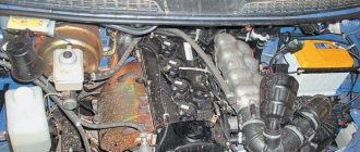
Hello everyone, the engine suddenly started to stall, especially when it was cold. Even after warming up, when the throttle was opened sharply, the engine shook noticeably. First of all, we change the spark plugs.
I had Denso TwinTip, but during the test you can change it to the good old AU17DVRM.
Denso were in good condition. Only one candle had a mark as if from a breakdown.
After replacing the spark plugs, the car started working and drove for two days, but then the problem returned.
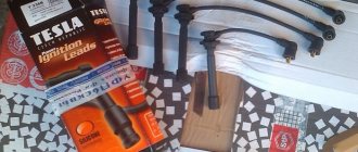
The next thing is to change the armored wires. Having studied the question, I wanted to purchase Tesla high-voltage wires, but I couldn’t find them on sale and the choice fell on the factory PES/SKK wires. I was pleased with these wires with their workmanship and price; the previous ones ran with me for more than 5 years without any problems.
Hello everyone! I once went in wet weather for a drive in a newly repaired Sena and didn’t recognize the car - it was stuck, the revs were floating, it adjusted at idle, it jerked while driving... I opened the hood and saw that over 8 years of service the high-voltage wires had become unusable, the charge was constantly draining from output of the 4 cylinder ignition coil to a nearby mounting bolt. Plus, the insulation on all the wires was damaged in the place where it fits into the clamps of the engine trim... The solution is clear - replacement with new ones. I climbed onto Existence and was literally blown away - a set of high-voltage wires costs from 3,000 rubles, with a two-week wait... A toad crawled out of the corner and began to whisper that original spare parts are of course good, but there is a crisis in the country, and in general there is little money after the holidays... Moreover, that the wires are made in Russia and it’s generally unclear why the hell this price is... I came to the store and bought wires for a VAZ 2110 injector 8 valves. I bought wires from the company HORS - all silicone, reinforced, blue for 380 rubles. I climbed under the hood, began to try it on, and it turned out that these wires are completely similar to the standard wires for the Sens, except for two small nuances: 1- The wire of the second cylinder is slightly shorter in length and because of this it cannot be completely removed into the standard channel of the engine trim. 2- The diameter of the internal connecting part of the protective moisture-proof cap on the ignition coil side is twice as large as required. Because of this, it is possible for water and other nasty things to get into the contact of the coil, which is accompanied by its failure. I thought and thought and decided that the tenfold difference in cost would pay for the existing shortcomings - which turned out to be very easy to eliminate.
General tips for connecting high-voltage wires.
Checking high-voltage wires. To check the wires, you will need a multimeter tester. Check the resistance of the wires - it should be no more than 20 KOhms (in practice, the longest wire of cylinder 1 has a resistance of up to 10 KOhms). If the wire resistance is more than 20 Kom, it must be replaced. Carefully inspect the wires for chafing on parts of the motor or other wires. In case of significant abrasion, replace the wire. In case of minor abrasion, it is possible to lay the wire so that it does not rub and fix it in this position.
Laying wires. Do not try to connect the wires in a bundle. Disassemble the wiring harnesses, release the wires from the plastic holders. Connect the high-voltage leads to the corresponding cylinder spark plugs. Lay the wires so that they do not rub against each other, engine parts, or hoses. Avoid sharp bends and tension on the wires. After connecting all the wires, secure them into the bundle with special comb holders included in the delivery kit.
The procedure for connecting I/O wires to a VAZ carburetor (2108, 2109, 21099)
The central wire from the distributor cover always goes to the ignition coil (bobbin).
The outlet of the distributor cover, which faces towards the front of the car, is connected to the first cylinder.
The outlet of the distributor cap, looking down, is connected to the third cylinder.
The outlet of the distributor cap, looking rearward, is connected to the fourth cylinder.
The outlet of the distributor cap, looking up, is connected to the second cylinder.
The procedure for connecting high-voltage wires to a VAZ Classic, Niva with a carburetor and distributor.
Central wire from the ignition coil (bobbin)
1 cylinder - above the vacuum corrector. Next, clockwise, the order is 1-3-4-2.
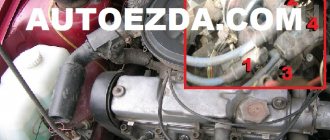
Injection VAZ produced before 2004 with an old-style ignition module (4-pin low-voltage connector)
Actually, on the module body it is already indicated which cylinder the pins correspond to - but we duplicated them in red in case the module gets completely dirty, and you might not be able to see it in the photo.
Injection VAZ produced after 2004 with a new ignition coil (3-pin low-voltage connector)
As with the old-style ignition modules, the new coils are also marked with pins corresponding to the cylinders. But the connection order is different from the order on the old-style ignition module. Be careful.
Resistance members
It starts poorly, jerks, does not pull... Very often, such engine ailments are treated by simply replacing high-voltage wires. The nature of the phenomenon is clear - we have written about it more than once. As is known, the spark energy depends on many parameters, including the power of the high-voltage pulse that reaches the electrodes of the spark plug. In other words, from losses in the ignition line. In a carburetor engine, the “science”, in general, ends there, but in an injection engine the influence of the control system is added. Indeed, if the combustion intensity is insufficient or if flares are missed, the feedback will work through the control system, increasing the fuel supply - to compensate for the supposedly excess oxygen. This will affect both gasoline consumption and especially the toxicity of exhaust gases. And if so, then each high-voltage wire actually becomes part of the engine control system!
Hence the purpose of our examination: analysis of the influence of various high-voltage wires on the main indicators of a real VAZ-2112 engine. As usual, everything was purchased from large metropolitan auto stores. We took two sets of wires from ten different companies - domestic and foreign. They took two for a reason - in order to prevent possible accusations of bias. Like, you can’t judge by one example! Let's not argue - it's better to change the verification procedure.
A laboratory ohmmeter was used to determine the resistance of each wire - all 80 of them. Then they measured the length of the wires, divided one by the other and got the linear resistance - in kilo-ohms per meter. Logically, for the same sets there should not be a large spread - the cable is cut from the same reel. But…
This happened in all sets from eight companies. But at Caesar in two wires it jumped almost an order of magnitude compared to the other six. Master Sport repeated the same picture, albeit for one wire. Little things? Maybe. But so that they do not distort the overall picture, we selected test kits for these brands so that the wires had approximately equal linear resistance, not without reason assuming that they would be quite standard. To compensate for the trouble, they allowed themselves to mutter that the manufacturer should have taken care of this.
Version of the module on the 8-valve VAZ-2110
At different times, different engines were installed on the VAZ-2110 car, both carburetor and injection. However, regardless of the type of power system and the number of valves (8 or 16), all engines are assembled on the unit base of the old engine 21083 and 21093. The most progressive of these engines is the 16-valve 1.6-liter VAZ 21124 engine with a power of 89 horsepower.
The top ten was equipped with two 8-valve engines of different sizes - 1.5 (2111) and 1.6 liters (21114). The ignition modules for these engines are different.
- The one and a half liter engine has a module with article number 2112-3705010,
- and the 1600 cc engine is equipped with module 2111-3705010.
A module for a 1.5 liter engine costs about 1500-2100, and the second one is 500 rubles cheaper.
The main task of the module is to distribute a high-quality spark sufficient to ignite the working mixture.
If this does not happen, problems begin with the motor:
- power drop;
- high gasoline consumption;
- failures during acceleration;
- unstable idle speed;
- engine failure when starting.
Different engines were installed on cars of this brand over the years. Some car owners have carburetor engines, while others have injection engines. Engines have different numbers of valves and types of power systems. There can be eight or sixteen valves. The motors for them were assembled on the basis of old engines 21083 and 21093.
The best of them is considered to be the sixteen-valve VAZ 21124, with a volume of 1.6 liters and a power of eighty-nine horsepower.
The top ten may have an eight-valve engine 2111, with a volume of one and a half liters, or an engine 21114, with a volume of 1.6 liters. The difference between them is in the ignition modules.
The module for a one and a half liter engine has the article number 2112-3705010, and the module with a volume of one thousand six hundred cubic meters has the article number 2111-3705010. They also differ in price. If the cost of the first ranges from one and a half thousand rubles to 2100, then the cost of the second is cheaper by about five hundred rubles.
Module structure
It consists of two ignition coils and two high-voltage switch switches. The coils are designed to create high-voltage pulses.
In essence, it is a simple transformer that has two windings: a primary winding, with an induction voltage of approximately five hundred Volts, and a secondary winding, with an inductive voltage of at least twenty kiloVolts. Everything is placed in one housing with one connector for signal wires and four for high-voltage.
Schematic diagram of the VAZ 2110 module
The operation of the ignition module is based on the “idle spark principle”. The module is capable of distributing a spark in pairs: to the first and fourth, second and third cylinders when transmitting pulses from the electronic control unit.
You can ring the VAZ-2110 ignition module yourself.
The main task of the module is to supply current to the spark plugs. A high-quality spark is enough to ignite the working mixture. If there is no spark, then problems with the engine are inevitable in the form of a decrease in power, an increase in fuel consumption, dips during acceleration, the speed fluctuates, and the engine refuses to work during startup.
If one coil fails, two cylinders stop functioning. This is easy to notice, since the engine becomes heated at idle, starting is difficult, gasoline consumption increases sharply, and dynamics are lost.
We remove the connector from the VAZ 2110 module by slightly moving the latch and pulling the wire.
We check the voltage between pin 15 and the block ground.
Circuit for checking the primary windings
https://www.youtube.com/watch?v=UeK9vNJr0xg
Secondary winding test circuit
Scheme for checking the module for short circuit
You need to make sure the spark plugs are working. They are unscrewed and the spark is checked separately on each of the spark plugs. A high-voltage wire is placed on the spark plug head. The spark plug is placed in such a way that the threaded part of the spark plug and the engine mass are in contact. If, when cranking the engine with the starter, the spark is very weak or absent altogether, then it needs to be replaced.
First of all, the body is carefully inspected, the surface of which must be intact. If chips, cracks or burns are detected, then the module must definitely be replaced.
If spark instability is noticed only on the first and fourth, or second and third cylinders, then the conclusion arises that some coil is damaged.
Even if this is the case, due diligence needs to be done.
Checking the VAZ-2110 ignition module with a multimeter 8 valves is as follows:
- The connector with signal wires is disconnected from the module.
- It is then removed from the module. The latch must be moved to the side and pulled by the wire.
- The ignition is turned on to check the voltage at the terminal of the central block of control wires. If there is no voltage when the battery is charged, or if the value is less than the nominal value, which is twelve volts, it is concluded that the electronic control unit is faulty.
- The high-voltage wires are removed, and it is necessary to unscrew and remove the module mounting bots.
- The resistance on the primary windings of the coils is checked. The multimeter is set to resistance measurement mode. Using the device, readings are taken from the rightmost and central terminals, then the leftmost and central ones are checked. The nominal resistance should be about 0.5 ohms.
- The primary windings are checked. The resistance in the secondary windings is measured between the terminals of the first and fourth, second and third high-voltage wires. Nominal resistance 5.4 kiloohms. If a discrepancy is found, it means that the coil is not operating correctly.
- The module is checked for a short circuit. One of the tester probes is installed on the central terminal, the other on the metal body. If there is no indication of a short circuit, a conclusion is drawn that the housing of one of the coils is short-circuited.
Errors
The error scanner detects a module malfunction. If the error codes are P-3000, P-3001, P-3002, P-3003 and P-3004, this is a lack of sparks. This means that the problem is either in the module itself, or the spark plugs are faulty, or the high-voltage wires, or the electronic control unit.
If the error code is P-0351, then the coil of the first to fourth cylinders is faulty, with the code P-0352 the second to third.
Such a scan does not say anything about the functionality of the module. The problem may be in the spark plugs or broken high-voltage wires. But if they were diagnosed before testing, then the ignition module is definitely to blame.
Here the car owner makes the decision. Only he can decide to repair it himself, or buy a new one. Choosing the second option will be simpler and faster, guaranteeing uninterrupted operation of the ignition system.
Many car owners are faced with the problem of their car not starting. If it suddenly turns out that high voltage has disappeared on the cylinders (either only on one, or on several at once), or the warning lamp does not light up, there is no spark, then the engine will not work. The ignition module may have failed. It's not always worth rushing to stores to look for something new.
Those who own a VAZ-2110 car are offered an alternative - repairing the ignition module themselves. The main thing is to have basic knowledge of auto electricians and the ability to understand circuits and contacts. It’s also a good idea to know how to use a digital multimeter in your work.
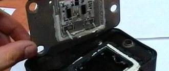
In order to disassemble the ignition module, you will also need knowledge of its components. This is a pair of ignition coils designed to excite high-voltage pulses, and a two-channel switch. Basically, high-frequency pulses can disappear in the 2nd and 3rd cylinders. You will have to start by removing the ignition module. The high-voltage wires are disconnected, then the VAZ-2110 ignition module itself is removed.
Unscrew the bolts
We get the board
Reassembling the sensor in reverse order
The essence of the repair is as follows:
- To open the aluminum plate you will need a straight screwdriver.
- Looking at the inside of the module, it may seem that everything is very complicated. Attention should be paid to the printed circuit board, which is coated with transparent silicone. The sealant is removed. To make the wires with which the board is connected to the contacts of the connectors and coils, too soft aluminum is used, so they become unusable. Such wires are torn off and thrown away. What should I put in place?
- You will need a computer mouse, which will have to be disassembled. It only requires stranded wires.
- The ignition module circuit includes two L497D1 switches, which are also manufactured by two fairly powerful transistors. The contacts are aluminum, so for soldering you will need a special flux for aluminum.
- First, the wires are soldered to the board itself. During manufacturing, the collectors are coated on top with a special metal that cannot be soldered. Therefore, before soldering the wires, the coating is removed from the metal.
- Then the plate is placed on the stove and heated to one hundred and eighty degrees, the heat will be distributed throughout the plate. This is important so that when the soldering iron comes into contact with the plate, the heat does not dissipate from it.
- Now you can proceed directly to soldering the wires to the module contacts. Try to make the wires as short as possible. Next, take a varnish (the varnish you use to paint your nails will also work), and use it to insulate the joints.
- Next, you need to check the ignition module. It must be functional. And the final touch: the inner surface is coated with autosealant, after which the assembly is completed. The wires should be positioned freely and not be pinched.
The work is not that difficult, and can be done by anyone who can work with a soldering iron and have basic knowledge of electronics.
If after repair it turns out that the cause of the malfunction was different, then this reason needs to be found, or go to the store for a new module.
Diagram, procedure for connecting VAZ high-voltage wires.
First, let's decide which of the four cylinders is first?
The first cylinder in front-wheel drive VAZs is located closer to the timing belt. If you look at the engine from the front, the first cylinder is the leftmost). And then everything is simple - from left to right - 1, 2, 3, 4.
In rear-wheel drive VAZ Classic and Niva, the first cylinder is located closer to the front bumper of the car.
Sn00pi › Blog › How to check BB wires? Troubleshooting.
How to check high voltage ignition wires?
Automotive high-voltage (HV) wires play an important role for internal combustion engines, since they help transmit high current from the ignition coil to the spark plugs. The serviceability and efficiency of the wires determines the timeliness and intensity of ignition of the fuel-air mixture, and therefore the correct and uninterrupted operation of the engine. Despite their simplicity, wires have many different “sores” and can cause a lot of troubles to their owner, which in one way or another will affect his nerves and pocket.
Malfunctions of high-voltage wires (common problems):
As a rule, the malfunction boils down to the fact that current either does not flow to the spark plug at all, or it does, but in limited quantities. This can happen for the following reasons: — There has been a break in the current-carrying wire through which the pulse travels. — There is a current leak, that is, the insulation is damaged and the current flows to the side. — The resistance exceeds the permissible value. — Problems in contacts (with a spark plug or ignition coil).
In the event of a break in the current-carrying wire, the effect of an internal spark occurs, in other words, an electrical discharge is formed between the ends of the broken wire, which reduces the voltage and causes an electromagnetic parasitic pulse. This impulse, in turn, negatively affects the correct operation of many of the vehicle's sensors. One such damaged high-voltage wire can cause vibration and interruptions in engine operation. Due to a damaged high-voltage wire, ignition in the cylinder occurs late or every other time, as a result, the synchronous operation of the cylinders and the engine as a whole is disrupted.
How to check high-voltage wires? Effective ways:
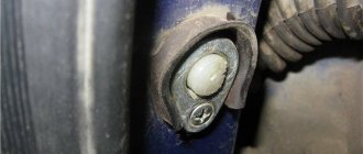
First of all, it is necessary to check the explosive for the absence of visible damage (cracks, fractures, etc.). Make sure there is no breakdown, this can be determined even without instruments, just look under the hood in the dark; in the event of a breakdown while the engine is running, a spark will be visible on the explosive wire. You can check high-voltage wires using a wire. To do this, you need to take a piece of wire in the dark and strip it on both sides. Then one end must be shorted to ground (machine body), and the other end must be drawn along the entire length of the explosive wires, as well as joints, caps, etc. A spark will form at the breakdown sites.
This is interesting: What to do if your car is stolen?
You can also check the resistance of the high voltage wires, for this you will need a multimeter. — Turn on the ohmmeter mode. — Remove the wire from the spark plug of the first cylinder and the ignition coil. — Connect the multimeter electrodes to the ends of the wire and look at the readings.
In good wires, the resistance should vary from 3.5 to 10 kOhm, depending on the type of wires themselves. Information about resistance is most often indicated on the insulation of high-voltage wires. Check each wire, the spread between them should not exceed 2-4 kOhm. If there is a large variation, replace the wires. By the way, they are changed as a set, that is, all together.
To complete your reading of the resistance of the most popular high-voltage wires: Tesla - 6 kOhm Slon - from 4 kOhm to 7 kOhm (4 kOhm - 1st cylinder and up to 7 kOhm - on the last cylinder) ProSport - almost zero resistance Cargen - 0.9 kOhm
Note! The resistance of high-voltage wires varies depending on the length, thickness, and material from which the wires are made.
General tips for connecting high-voltage wires.
Checking high-voltage wires. To check the wires, you will need a multimeter tester. Check the resistance of the wires - it should be no more than 20 KOhms (in practice, the longest wire of cylinder 1 has a resistance of up to 10 KOhms). If the wire resistance is more than 20 Kom, it must be replaced. Carefully inspect the wires for chafing on parts of the motor or other wires. In case of significant abrasion, replace the wire. In case of minor abrasion, it is possible to lay the wire so that it does not rub and fix it in this position.
Laying wires. Do not try to connect the wires in a bundle. Disassemble the wiring harnesses, release the wires from the plastic holders. Connect the high-voltage leads to the corresponding cylinder spark plugs. Lay the wires so that they do not rub against each other, engine parts, or hoses. Avoid sharp bends and tension on the wires. After connecting all the wires, secure them into the bundle with special comb holders included in the delivery kit.
The procedure for connecting I/O wires to a VAZ carburetor (2108, 2109, 21099)
The central wire from the distributor cover always goes to the ignition coil (bobbin).
The outlet of the distributor cover, which faces towards the front of the car, is connected to the first cylinder.
The outlet of the distributor cap, looking down, is connected to the third cylinder.
The outlet of the distributor cap, looking rearward, is connected to the fourth cylinder.
The outlet of the distributor cap, looking up, is connected to the second cylinder.
The procedure for connecting high-voltage wires to a VAZ Classic, Niva with a carburetor and distributor.
Central wire from the ignition coil (bobbin)
1 cylinder - above the vacuum corrector. Next, clockwise, the order is 1-3-4-2.
Injection VAZ produced before 2004 with an old-style ignition module (4-pin low-voltage connector)
Actually, on the module body it is already indicated which cylinder the pins correspond to - but we duplicated them in red in case the module gets completely dirty, and you might not be able to see it in the photo.
Injection VAZ produced after 2004 with a new ignition coil (3-pin low-voltage connector)
As with the old-style ignition modules, the new coils are also marked with pins corresponding to the cylinders. But the connection order is different from the order on the old-style ignition module. Be careful.
VAZ models 8 and 16 valves
Despite the similarity in engine design, the ignition system of the 1.5-liter injection 16-valve engine differs from the 1.6 16-valve engine. The 1.6 liter engine uses an electronic contactless ignition system with individual coils on each spark plug. Therefore, there was no need for an ignition module. Such a system is more reliable and cheaper to operate, since if one coil fails, there is no need to replace the entire module.
The 16-valve 1.5-liter VAZ 2112 injection engine used the same non-contact ignition system as the 8-valve engine, but a different ignition module was installed. Its catalog number is 2112-3705010. The design of the module remains the same - two ignition coils (for cylinders 1-4 and 2-3) plus switch keys in a single block.
Connection features
The order of connecting high-voltage wires must be strictly sequential, since each cylinder of the engine corresponds to a specific socket on the ignition module. Considering that there is a numbering of the sockets on the ignition module body, the risk of confusing anything is minimal.
The procedure for connecting high-voltage wires of the VAZ 2114 injection type depends on the year of manufacture of your car. Fourteen cars before 2004 had 4-pin ignition modules installed, and cars after 2004 had 3-pin coils.
The connection diagram for VAZ 2114 high-voltage wires to the ignition module (until 2004) is as follows:
Connection diagram for VAZ-2114 with ignition coils (after 2004):
In the pictures you can see the numbers of the landing slots. Each number must have a corresponding cylinder connected to it (cylinder numbering is counted from left to right).
To correctly install high-voltage wires on the VAZ 2114, follow the following algorithm of actions:
- Turn off the ignition. Open the hood and remove the power terminals from the battery;
- We remove the old GDPs from the mounting sockets on the module and cylinders;
- We remember the location of the high-voltage wires of the VAZ 2114 and connect new GDPs according to the diagram. Before replacing, it would not be amiss to draw this very diagram by hand on paper so as not to confuse anything;
- We connect power to the battery and, to check whether we did everything correctly, start the engine.
When installing the wiring, do not try to connect individual air intakes to each other with plastic clamps; to do this, you must use the comb holder that comes with them. A thin clamp can easily wear through the insulating coating. Also make sure that the GDP does not bend.
Connecting armored wires on VAZ 2115 and 2113 is carried out in a similar way.
Wiring replacement process
The procedure for removing and installing the ignition coil on old VAZ models:
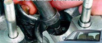
- First, disconnect the central high-voltage wire leading to the distributor (ignition distributor).
- Disconnect all power wires from the coil contacts. Since they are fastened with nuts, you will need an 8 wrench for this.
- If you don’t know which wires to connect to which connector later, it’s better to immediately remember or mark them somehow, so that later during installation you can connect them correctly.
- Unscrew the coil housing. It is attached to a clamp (clamp), which is pressed to the car body with two nuts.
- After the work has been done, you can remove the ignition coil and replace it if necessary.
For new type VAZ cars:
- We remove the “minus terminal” from the battery.
- Remove the top protective cover of the engine. If the engine volume is 1.5 liters, then this part is missing and this step is skipped.
- We remove the high-voltage wires from the coil.
- Now, using a 13mm wrench, unscrew the two fasteners.
- Using a 17mm wrench, loosen one bolt securing the coil.
- We take out the module.
- Use a hexagon to unscrew the coil from the holder.
- Assembly is carried out in reverse order.
Replacing the ignition coil on a VAZ is quite simple. Even a novice motorist can do this in his garage, and if everything seems too complicated, contact a car service center. Particular attention should be paid to the choice of product, since this will determine how well the engine and ignition system will work.
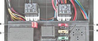
Cylinders are numbered from left to right. In the module, the internal ignition cylinder 1 is located on the lower left side. The second and third cylinders are located in the left and right compartments, respectively. The output of the fourth cylinder is located at the bottom in the right compartment.
How often should GDP be changed?
According to the recommendations of Avto-VAZ, replacement of high-voltage wires of the VAZ 2114 should be done every 30 thousand kilometers. In practice, motorists rarely comply with these replacement deadlines, since if the wires do not have any mechanical damage, they can travel about 100-150 thousand km.
When the service life is exceeded, the internal resistance of the GDP increases, which negatively affects the transmission of the electrical impulse. This leads to problems with ignition and acceleration dynamics, since when the supply of current to the spark plugs is delayed, the normal engine operating cycle is disrupted.
Change the wires every 25-30 thousand and everything will be fine
Purpose
Gasoline engines operate by burning fuel in the cylinders, ignition is carried out using a spark plug, which generates a spark. The supply and distribution of current is handled by the ignition system, in which high-voltage wires play a very important role. Through them, high-voltage voltage is transmitted directly to the spark plugs from the ignition module. Transporting voltages reaching 15,000 volts is quite a serious task, which the wires must cope with without difficulty.
Functionality check
To accurately determine whether it is time to change the high-voltage wires of the VAZ, you need to check their performance with a multimeter.
This operation will take you no more than 15 minutes:
- Turn off the ignition;
- We remove the wires: disconnect the first end from the ignition module, the second from the cylinder;
- We switch the tester to ohmmeter mode and connect the multimeter probes to the wire contacts.
If the high-voltage wires on the VAZ 2114 are in normal technical condition, the multimeter will show a resistance within the value indicated on the wire insulation; if the readings are different, the armored wires on the VAZ 2114 need to be replaced. The process must be repeated on each wire in turn.
If the test shows disappointing results, there is a possibility that the problem of increased resistance lies in oxidized contacts. In this case, you can try to revive the VVP by wiping the contacts with VD-40 or carburetor cleaning fluid.
Also, the cause of problems with ignition can be a breakdown of the GDP. You can determine it visually in the dark - take a flashlight and open the hood of the fourteenth, find and inspect the armored wires, if you notice a slight spark on the insulation - the air intakes are broken and need to be replaced.
Symptoms of module malfunction
Signs of a faulty ignition module on a VAZ-2110 are always acutely felt:
- hesitant engine starting or failure to start;
- failures during sudden changes in speed;
- high fuel consumption;
- two cylinders do not work, the engine is feverish;
- lack of dynamics;
- a sharp drop in power;
- drop in power and thrust after warming up.
Other faults
These symptoms may not only be caused by the ignition module. To determine the malfunction, it is enough to spend a few minutes diagnosing spark plugs, high-voltage wires and caps. This will eliminate the remaining elements of the ignition system and make sure that it is the ignition module that is faulty.
- Checking the spark plugs. To do this, unscrew them, put on the caps, place them on the cylinder head and crank the engine with the starter. The spark should be stable on all spark plugs. We replace non-working spark plugs and repeat the test. Under no circumstances should you crank the engine with the starter with the high-voltage wires removed. This will lead to a breakdown in the ignition module cover.
- Checking the high voltage wires. We remove the caps and hold the wire contact through the insulator at a distance of 10-15 mm from the head. With good wires, the spark should pierce this distance vigorously and confidently. Next we check the wires for resistance. A working wire should have a nominal resistance of 7-10 kOhm. Any deviation from this value indicates the need to replace the entire set of high-voltage wires.
- We check the caps for breakdown.
We also look at the block and especially the wires included in it.
In addition, it is better to check the spark plugs and wires on a warm engine, since a half-dead ignition module can operate cold for some time and fail when heated. You also need to be sure that all sensors are working properly. This can be indicated by an error code or Check Engine light.
Algorithm for checking the ignition module on a VAZ-2110
We begin the test with the block connected to the module.
To check the module, we only need a multimeter and it will take 15-20 minutes. This is quite simple to do, the main thing is to adhere to the algorithm and know the nominal values of the working module:
- We check the power supply and the presence of pulses supplied from the ECU. We check the power between the central terminal (15) of the wire block connected to the module and the engine ground. When the ignition is on, the voltage should not be less than 12 V. Otherwise, either the battery is dead or the ECU does not work.
- We check the pulses from the ECU on the wiring block. We install one tester probe on connector 15, the second on the far right, then on the far left. The assistant cranks the engine with the starter, and at this time we record short-term voltage surges with a tester. If there are no impulses from the ECU, it is he who is to blame.
- We check the resistance on the secondary windings of the coils. We put the tester in resistance measurement mode and measure it at the high-voltage terminals of the module cover. Between pins 1 and 4 and pins 2-3, the resistance should be 5.4 kOhm. Otherwise, the module must be replaced.
- We check the resistance of the primary windings between contacts 15 and the rightmost, then the leftmost terminals. Nominal - 0.5 Ohm. Deviation is not allowed.
- Check the module for a short circuit. In ohmmeter mode, install one multimeter probe on the central terminal, the second on the metal body. There shouldn't be any resistance. If the device detects at least some resistance (other than unity or infinity), the module must be replaced.
Kiel Blinton 05.12.2010 - 17:56
Good day everyone! Forgive me if the topic is button accordion, but there is no one else to ask. Question - I have an engine 2110 engineer, I bought high-voltage wires and foolishly removed the old ones, but I didn’t remember the connection sequence. If I am facing the car, then the numbering of the candles is 1 2 3 4? But how do they all connect to the square ignition module? If anyone knows, please explain or draw a diagram, please.
Attached images
Post edited by Kiel Blinton: 12/05/2010 - 18:03
Advertisements on NN.RU - Auto
A specialized company for converting trucks into tow trucks invites you to install a tow truck platform on.
The company offers you to upgrade the Fiat Ducato Fiat Ducato basic version for a solution.
Power take-off boxes Kamaz, Maz, Ural, Kraz, Gas, Zil Dispatch on the day of payment. Sending by transport companies. We work as with. Price: 18,500 rub.
With us you can not only extend the frame to fit a body of 5.1 m, 6.2 m, 7.5 m, 9 m for Maz Zubrenok, Maz, Kamaz, Ural, Zil, Mitsubishi, Nissan.
Today, Nizhny Novgorod fast food lovers have a real holiday: a new worldwide outlet has opened on the renovated Nizhne-Volzhskaya embankment.
An accident occurred in the Moskovsky district of Nizhny Novgorod: a girl was swinging her friend, but the swing suddenly fell. As a result.
A street film festival will be held in Nizhny Novgorod for the second time. Short films by young Russian directors will be available for free.
Imagine, you wake up in the morning, open the curtains, bright sunlight bursts into your apartment, and outside the window is a stunningly beautiful landscape.
Source
Sereshka 05.12.2010 - 18:01
Kiel Blinton (05.12.2010 - 17:56)
:
Good day everyone! Forgive me if the topic is button accordion, but there is no one else to ask. Question - I have an engine 2110 engineer, I bought high-voltage wires and foolishly removed the old ones, but I didn’t remember the connection sequence. If I am facing the car, then the numbering of the spark plugs is 1 2 3 4. But how are they all connected to the square ignition module? If anyone knows, please explain or draw a diagram, please.
There should be numbers on the module itself.
Location
On VAZ 2110 injection engines, high-voltage wires are attached at one end to the ignition coil, which is located on the front side of the cylinder block slightly to the right of the center, and the other end is connected to the spark plugs. On carburetor engines, the circuit is exactly the same, only instead of a coil, the wires go to the distributor, which is installed to the right of the cylinder head.
It should be noted that the number of wires in the injection version of the VAZ 2110 is less than in the carburetor version. The “tens” injection engine uses 4 high-voltage wires, and the carburetor engine uses 5.