All modern cars are equipped with a honeycomb exhaust gas emission neutralizer - a catalyst. It is named after the principle of chemical reactions occurring there, where the noble elements of the filling accelerate and make possible the processing of harmful substances into neutral ones at high speed. But sometimes this useful device itself becomes a source of big problems.
Do you need an oxygen sensor emulator?
- The ECU puts the engine into emergency mode when the engine operates according to the specified fuel maps without taking into account the readings of the oxygen sensors.
- The “Check Engine” indicator lights up on the dashboard and an enriched fuel mixture enters the cylinders.
- Soot on the spark plugs increases, the power of the internal combustion engine decreases and the oil becomes contaminated.
- Increased fuel consumption entails extra financial costs.
Almost all automakers recommend replacing a faulty converter. But not every car owner will do this, because the price of some copies, for example, for VAZ, reaches 60,000 rubles. It is also worth adding the cost of installing the device. Therefore, many car enthusiasts are interested in what a do-it-yourself catalyst blende is and the scheme for its implementation.
The essence of the emulator's operation is to change the real sensor readings, after which the ECU switches to normal operation. In this case, the neutralizer itself can be cut out or replaced with a flame arrester. The procedure for installing a simulator is no more complicated than increasing the ground clearance of a Renault Duster.
Diagnostic methods
It is advisable to carry out diagnostics of the sensors every 10,000 km of the vehicle or at the first signs of a probe malfunction, which are described below.
Multimeter
Very often, the reason for the oxygen probe not working is damage to the heater coil or contact with the heater. It is easy to check whether this is true with a multimeter by switching it to the ohmmeter operating mode. Typically, pins 3 and 4 (in a 4-wire sensor) go to the heating element. The resistance value should be within 4.5 - 5.5 Ohms. If the readings exceed this value, the probe requires replacement because the heating element has failed.
To check the signal received by the electronic unit, you need to start the car, press the gas pedal to keep the engine in high-speed mode for some time. We connect the signal wire of the probe (usually black) to the positive probe of the multimeter, and connect the negative probe to ground, switching the device to voltmeter mode (2000 mV). When you hold down the gas pedal and suddenly release it, the readings of the device should be in the range from 1000 mV to 100 mV. If the readings remain unchanged within 400 - 500 mV when manipulating the gas pedal, then the probe is faulty.
Oscilloscope
The quality of testing with an oscilloscope is manifested in the ability to find out the time period of change in the output voltage signal. To check, you need to connect the oscilloscope to the wire that gives a signal to the electronic unit (black). Next, you need to start the engine and wait until it warms up to 70˚C. As the sensor warms up to 400˚C, the device will begin to show a wave-like graph. When the engine is running at about 3000 rpm, the device should show a smooth wave-like graph with a low signal level limit (at least 0.1 V) and a high signal level (no more than 0.8 - 1 V).
If a graph is drawn on the screen at the extreme (upper or lower) points, as well as at a position of about 0.6 V at maximum engine operation, then the λ probe is faulty.
How to make a mechanical corrector for the exhaust system?
To implement a mechanical blende for the catalyst with your own hands, it is recommended to use blanks made of heat-resistant steel or bronze. This way the parts will not be deformed due to high temperature. There are two designs, but both options require a lathe or the help of an experienced turner.
First option
It is a sleeve 40-100 mm long. On one side, a standard sensor is screwed in, and on the other, the circulation of gases is limited by a small diameter hole. The essence of the “device” is that the composition of the exhaust mixture is averaged, because the lambda probe is removed from the gas stream itself and, accordingly, catches fewer toxic substances. Due to this, it is possible to deceive the ECU.
A typical drawing with spacer dimensions can be changed in terms of dimensions, it depends on the model and brand of the car. The optimal inlet diameter remains unchanged - 1.5-2 mm. In some cases, the length of the bushing may not allow it to be installed in its original place. As a result, you have to weld the mount elsewhere in the exhaust pipe.
Second option
- Exhaust gases enter the bushing body through a small diameter hole.
- In the volume of the spacer, excess CH and CO are subject to oxidation by oxygen, as a result of which the concentration of harmful substances decreases.
- The ongoing processes change the shape of the sinusoid, and the electronic system believes that the catalytic converter is operating normally.
A do-it-yourself catalyst blende made according to the above diagram has advantages similar to the previous option. Here the standard probe will be raised by 32 mm, although this is less than 40-100 mm.
Features of spacer installation
The installation procedure is not difficult, and begins with placing the car on an overpass or lift. Further actions occur according to the following scheme:
- Disconnect the negative terminal of the battery.
- Unscrew the controller.
- Screw the bushing onto the probe.
- Screw the upgraded unit into place.
- Connect the battery.
Types of homemade decoys
To understand the principle of operation of the emulator, it is worth considering each type separately, since the lambda probe trick works differently in each case. The key goal of the emulator is to “fuss the brains” of the car’s ECU if the catalytic converter is broken. The decoy gives a signal about the optimal operation of the catalyst and the permissible oxygen content in the exhaust. So, let's look at three ways to deceive the electronics of a modern car.
Reflashing the controller
The only requirement in this case is to use the services of a specialist if you are not strong in electronics. It is advisable to use the method in case of failure of both the sensor and the catalyst. It is necessary to electronically disable the oxygen sensor by entering the appropriate program. Next, the appropriate changes are made and, if everything is done correctly, a message about critical faults will no longer be displayed on the dashboard. The engine will operate as usual without a lambda probe. The main problem with this method is that if done incorrectly, the computer will no longer operate at its optimal level. This can only be corrected by factory firmware, which is expensive and generally not so easy to obtain.
Mechanical emulator
Making a lambda probe with your own hands in the mechanical version is much easier. Essentially, it’s just a spacer called a bushing; it is installed in the area between the probe itself and the place where the sensor is fixed. We are talking about the surface of the collector or exhaust pipe. Bronze or high-quality heat-resistant steel is used to make the bushing. Visually, it is a hollow cylinder containing crushed ceramic chips inside. A thin axial hole and thread are located on the side of the spacer to which the exhaust system element is fixed.
As for the implementation of this method, it is necessary to change the position of the sensor so that it is further from the exhaust pipe or manifold. After passing through a thin hole, the exhaust gases will fall to a small extent on the ceramic chips, where they will enter into an oxidation reaction under the influence of the temperature factor. Of course, the content of harmful substances will be significantly reduced. Considering the fact that this method involves to some extent deceiving the sensor, the advisability of its use is observed only in the event of a catalyst failure. The latter must be replaced with a flame arrester or completely removed from the exhaust system.
You can make a mechanical overlay yourself without any extra effort if you have the skills of a lathe. Prepare a bronze or steel blank, a lathe and a diagram of the part with the necessary parameters. If turning skills are not your thing, just buy a finished part or order it with the specified parameters. The cost of the finished version can range from 200 to 800 rubles - it all depends on the complexity of the product and its variety.
As for the further installation of a part purchased or made by yourself, there will be no problems in this case, even if you do not have special skills. Find where the oxygen sensor is located, unplug it, remove it and install the bushing in its place. Next, simply screw the sensor into the spacer and connect the modified structure to the network.
Electronic snag
A more complex device from a technological point of view is the electronic decoy of the lambda probe. The feasibility of its use is also observed in similar cases of failure of factory parts. The secret of functionality lies in converting the signal from the sensor into a signal with characteristics corresponding to optimal operation of the catalyst.
The snag should be connected directly to the wires going from the probe to the controller.
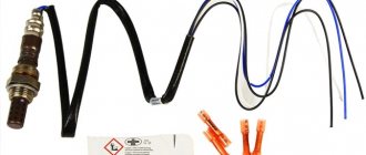
A programmable microprocessor often acts as the basis for this kind of deception, but you can assemble a basic interpretation yourself if you know how to use a soldering iron. The relevance of using the emulator described below is observed when the second sensor, located in the area after the catalyst, fails. This option is extremely primitive at first glance, but in practice its performance has been repeatedly proven. Prepare the following materials:
- soldering kit, including everything you need;
- resistor with a resistance of 1 Mohm;
- a non-polar capacitor with a capacity of 1 µF.
Traditionally, the electronic snag of the second lambda probe has two black, white and blue wires.
The sequence of installing the blende is as follows:
- At the initial stage of work, the ground wire must be completely disconnected from the battery.
- We don't need black ones, just break the blue conductor and install a resistor at the break site.
- The blue and white wires should be connected through the capacitor.
- The area under the connector is the most suitable place to install such a homemade emulator. This could be in the engine compartment, under the dashboard, or between the front seats.
Do-it-yourself electronic catalyst blende and emulator circuit
A real electronic emulator is a microprocessor device consisting of a single-chip microcircuit. The principle of its operation is based on the formation of an output signal, which in shape corresponds to the information in the working neutralizer. This option is difficult to do on your own, so you should immediately consider a simpler method. To implement it you need to prepare:
- Electric soldering iron.
- Solder and rosin.
- Knife and side cutters.
- Resistance 200 Kom, power 0.25 W.
- The capacitor is non-polar with a capacity of 4.7 microfarads.
The principle of operation of the system is to average the readings of the oxygen sensor, which is installed after the converter. The method of connecting emulator components is simple and universal. All elements are connected directly to the vehicle’s on-board network conductors. Before connecting the electronic decoy to the catalyst with your own hands, you should disconnect the battery to eliminate the possibility of a short circuit. After the implementation of the project, the car demonstrates good dynamics. However, the effect of over-enrichment of the combustible mixture may occur, which causes the deposition of a layer of soot in the exhaust manifold. In addition, on some models error P0133 appears, indicating a low response rate of the lambda probe.
Clean the lambda probe
Often soot accumulates on the oxygen sensor, and combustion products settle inside. This prevents him from working at full capacity. The car loses traction, the maximum speed decreases and fuel consumption increases. One solution to the problem is cleaning the lambda probe.
How to clean the oxygen sensor:
- Before cleaning the probe, inspect it carefully. If there is damage or the structure is deformed, then the malfunction is unlikely to be related to contamination. If there is no damage, then the lambda probe can be cleaned.
- You will need orthophosphoric acid, which effectively corrodes scale and removes soot. Do not use mechanical cleaning tools: iron brush, sandpaper, needle file, etc. You will damage the precious metal layer and the sensor will become unusable. Remove the oxygen sensor from the car and place it in acid. To speed up the process, take a soft brush and apply the liquid evenly over the entire surface.
- Phosphoric acid cleans the lambda probe in 15–25 minutes. Afterwards, rinse the device with warm water and dry thoroughly.
What do spare parts manufacturers offer?
On the shelves of auto stores you can find all kinds of parts for tuning the exhaust system. The production of mechanical simulators of the normal operation of the catalytic converter is made of bronze or chrome-plated steel. The price of such devices ranges from 400 to 800 rubles, and a standard installation at a service station will cost about 500 rubles.
A spacer with a minicatalyst is offered much more expensive than its elementary counterpart, its cost is 1,500-4,000 rubles. Simple electronic emulators of industrial production are sold for 1,500-3,000 rubles. The range of prices for flashing ECU software is quite wide - from 1,000 to 30,000 rubles.
Good day everyone! In previous entries I wrote that I wanted to install a lambda probe (mechanical) but the idea was not successful... - I could not unscrew the sensors...
In the end, I decided to make an electronic deception and install it, read a lot of information on the Internet, consulted with smart people and began to implement the decoy =)
Then, as usual, the photo is of poor quality =)
I don’t have a photo from the installation, I didn’t have time to make it clear from the diagram how to install it
I’ll tell you a few things right away:
1. wires we have black (signal), gray (ground) and 2 white (heating)
2. experimentally and on the advice of “experienced” people, it turned out that all the diagrams on the Internet are nonsense... the installation is correct, but the components are not the same...
Everywhere they write that you need to install a non-polar capacitor - I agree with this, but a 1 MΩ resistor gives a not entirely accurate amplitude on an oscilloscope... yes, if Jackie-Chan appears, this option will work, but the sensor will not work quite accurately... But during installation a 150 kOhm resistor, the amplitude will be almost similar to the amplitude when there is a catalyst...
in general, think for yourself... I decided to try both options... 1 was dropped immediately, because after riding for a couple of days, I didn’t notice any difference at all, but when I installed the second option... then it’s a completely different matter! I’ve been driving with it for about a week now, so far the consumption has dropped, but not by much... earlier, with active driving, the BC showed more than 13 liters... which was not pleasing, now it’s 10.5 with active mode, 9 with “grandfather” mode, in general, consumption has dropped and is not increasing =)
Excerpt from Murzilka:
Excess air in the mixture is measured in a very original way - by determining the residual oxygen content (O2) in the exhaust gases. That's why the lambda probe is located in the exhaust manifold in front of the catalyst. The electrical signal from the sensor is read by the electronic control unit of the fuel injection system (ECU), which in turn optimizes the mixture composition by changing the amount of fuel supplied to the cylinders. Some modern car models have another lambda probe. It is located at the outlet of the catalyst. This achieves greater accuracy in preparing the mixture and controls the efficiency of the catalyst.
Symptoms of a malfunctioning lambda probe
Eternal things created by human hands do not exist. Any technique designed for fine analysis can fail for many reasons. Oxygen sensors are no exception.
Let's consider in detail:
- Increased CO level. It is possible to determine the concentration yourself, only with the help of instruments. Almost always, the indicators indicate a probe malfunction.
- Increased fuel consumption. Injection cars are equipped with a display indicating the amount of fuel consumed. An increase can also be judged if the frequency of refueling is higher than usual.
- The light alarm, focused on the operation of the lambda probe, is constantly on. This is the Check Engine light.
In addition to the described signs of destabilization of the oxygen sensor, you can evaluate the quality of the exhaust gas visually - light smoke indicates oversaturation of air in the mixture, clouds of thick black smoke - on the contrary, an excessive overconsumption of fuel.
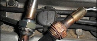
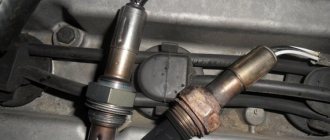
Visual inspection
Finding the oxygen sensor is not difficult; it is located on the exhaust pipe closer to the manifold. There can be two of them, one before the catalyst, the second after and connected through the controller.
First, inspect the integrity of the wires leading to the device and how tightly the contacts fit.
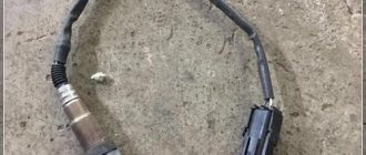
Unscrew the lambda probe from the exhaust pipe and inspect it. The presence of deposits in the form of soot, white, gray, or shiny plaques should suggest that before checking the lambda probe, it needs to be cleaned.
If the device is deformed, it must be replaced immediately; read the topic - how to replace a lambda probe.
Further testing can be carried out using instruments, but you need to understand that, for example, a voltmeter has limited functionality and it is impossible to measure resistance and current, so it is better to immediately acquire a multimeter or other similar tester with advanced capabilities.
Check with a voltmeter and multimeter
A common case is when the lambda probe has four wires. Two are signal ones, and two go to the heater.
The pinout of two, three and four wire lambda probes is shown below.
First you need to check the reference voltage, since this can be done with the engine not running.
Turn on the ignition, take a voltmeter, set the switch to 2 or 20V. We find two signal wires (how to do this is described below) and connect a voltmeter to them, the readings should be in the range of 0.45 - 0.50 volts. These measurements can also be made using a multimeter.
ATTENTION: three wired oxygen sensors do not have a signal ground wire, so we connect the negative wire of the voltmeter (multimeter) to the car body.
Next, we start the car and while the oxygen sensor is warming up (it is checked only after warming up to more than 300 ° C), we check the heater (voltage and resistance).
IMPORTANT: the check must begin with the heater, and then the entire device. The fact is that if there is no power at the heater connector, the sensor may either not work at all, or work very poorly, inadequately and with delays.
We need to check whether 12V voltage is supplied to it; this can be done by finding the necessary wires by color (see pinout above). On most sensors they are white.
We take a voltmeter and check the voltage, everything is simple. This can be done even simpler, turn on the ignition without starting the car, but the resulting measurement result must be compared with the voltage at the battery terminals.
But there are situations when the wiring is so worn out and discolored that it is impossible to determine its color.
Therefore, we take a voltmeter or multimeter, connect the negative wire to the car body, and touch each wire with the positive wire in turn until 12 or a figure close to it appears on the voltmeter.
This way you can find the positive wire of the heater. To search for the negative one, without disconnecting the voltmeter contact from the found positive wire, we alternately connect the second end to the remaining three until a figure close to 12 appears on the voltmeter, as in the first case.
We remember the position of the signal wires and those going to the heater.
If no voltage was detected on the positive wire, check its condition. Typically it is connected directly to the fuse box.
If the negative wire is not working, then it’s more complicated, it goes to the ECU, if there is no break and it rings, then the problem may be in the control unit.
You will also need to measure the resistance of the heater; for this you will need a multimeter. Measurements can also be taken on a removed O2 sensor without a car.
The standard value is from 2 to 10 Ohms, but for each brand of car it can vary greatly; standards of 4.5 - 6 Ohms are often found.
- Take a multimeter and switch it to resistance measurement mode;
- We connect the device to the heater wires;
- We take measurements.
If the resistance is not normal or the number on the device is 1 and nothing happens, then there is an open circuit in the circuit, change the 02 sensor.
We check the operation of the lambda probe through the signal wires
We will check the lambda probe with 4 wires. For this it is better to use a multimeter. The engine is already warmed up, if not, then start the car and let it idle for 5-10 minutes.
We need the ceramic element to warm up and the ECU feedback modes with the oxygen sensor and fuel supply control to turn on, and this happens after the engine has warmed up to 60-70C.
You cannot disconnect the oxygen sensor from the block; to connect to the wires you need to use sharp needles at the ends of the multimeter wires.
Connect the tester to the signal wires in parallel - plus to “+”, minus to “-”, the engine should run.
Pay attention to the voltage indicator, if it is equal to the reference 0.45V and the number is constant, then the lambda probe is faulty.
If the voltage cyclically jumps in the range from 0.1 to 0.9 volts with a frequency of 1.5 - 2 times per second, then the lambda probe is working, otherwise it must be replaced.
If the readings hover either at the bottom (0.1 - 0.3V) or at the top (0.8-0.9V), then the feedback mode may not have turned on yet, which is activated after the engine warms up to 60 - 70 degrees Celsius. Those. The sensor itself has already warmed up, but the mode has not yet been activated.
There is another way to connect a multimeter to an oxygen sensor. Press the negative wire to the body (ground), and the positive wire using a needle through an elastic band to the black wire (positive). Take readings.
What other readings can the multimeter give and what do they mean?
A constant value of 0.8 - 0.9 volts indicates that the fuel mixture is constantly enriched (high-calorie), and there is little oxygen.
This will be indicated by a number of other signs (popping sounds in the muffler, the color of the smoke from the exhaust pipe has changed, and so on.
The causes of the problem should immediately be sought in:
- dirty air filter;
- ignition and fuel system adjustments;
- incorrect operation of injectors (fuel is pouring);
- failure of the air flow sensor;
- improper operation of the economizer;
- other reasons.
If the multimeter readings remain unchanged within 0.1-0.2 volts, then the mixture is constantly lean (a lot of oxygen, 15-17 kg per 1 kg of gasoline). Or, conversely, oxygen is normal, but little gasoline is supplied, with the same ratio of 17 to 1.
There are many reasons for excess air in the cylinders, first of all, you need to look at the exhaust manifold gaskets, whether the brake booster diaphragm is torn, whether the crankcase ventilation system is working correctly (check whether the oil filler plug is screwed in tightly, whether the oil dipstick is inserted tightly - air should not get into crankcase from outside).
If you suspect that there is not enough fuel supplied, then remember the last time the injectors were cleaned or the fuel filter was changed. Pay attention to the fuel pump, most likely its service life is coming to an end and it is working at its limit.
There may be other faults, the diagnosis of which requires a professional approach.
You can check it in another way.
We carry out tests for rich and lean fuel mixtures
To perform a rich fuel mixture test, do the following:
- It is better to do the test on an already warmed up engine and with a partner;
- Disconnect all wires from the sensor, while it should be in its normal place;
- Connect a multimeter to the lambda probe (in 2 or 20 volt modes);
- Start the engine and increase the crankshaft speed to 2600 per minute;
- Reduce the speed sharply and immediately disconnect the pipe from the vacuum pressure regulator, i.e., artificial enrichment of the fuel occurs;
- Record the readings of the multimeter, they should be within 0.7 - 0.9 volts. If there are no dynamics of changes or the numbers are far from those indicated above, it means that the lambda probe is faulty.
Lean mixture check:
- With the car running, take the end of the already removed vacuum pressure regulator tube and create an air leak in it using any convenient method (artificially lean the mixture);
- At the same time, measure the readings of the multimeter, they should be within 0.1 - 0.2 volts. In this case, the readings should change in less than 1 second.
How to conduct a test for dynamic operating modes is shown below.
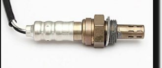
Oxygen sensor
The lambda probe is a residual oxygen sensor. Installed in the exhaust manifold of vehicle engines, as well as in the chimney of modern heating boilers. Indicated by the Greek alphabet symbol λ probe. In simple terms, a lambda probe is a sensor that reads how much unburnt oxygen is left in the exhaust gases. To comply with international environmental standards, car manufacturers are required to install such electronic devices. They reduce the amount of harmful substances.
Catalytic convectors burn carbon and nitrogen oxides in the exhaust system before it all goes outside. The lambda probe is one of the components of this device and is an integral part for the proper operation of the device. Why and how to fake a lambda probe?
Due to the poor quality of the road surface and not always high-quality fuel, it often happens that the lambda probe breaks along with the catalyst.
In this case, it is necessary to replace broken parts or install a fake oxygen sensor.
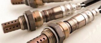
Types of lambda probes
Modern cars are equipped with the following sensors:
- Zirconium;
- Titanium;
- Broadband.
Titanium
Visually similar to zirconium. The sensor's sensitive element is made of titanium dioxide. Depending on the amount of oxygen in the exhaust gases, the volumetric resistance of the sensor changes abruptly: from 1 kOhm with a rich mixture to more than 20 kOhm with a lean mixture. Accordingly, the conductivity of the element changes, which the sensor signals to the control unit. The operating temperature of the titanium sensor is 700°C, so the presence of a heating element is mandatory. There is no reference air.
Due to its complex design, high cost and fastidiousness to temperature changes, the sensor is not widely used.
In addition to zirconium, there are also oxygen sensors based on titanium dioxide (TiO2)
Broadband
Structurally differs from the previous ones in 2 chambers (cells):
- Measuring;
- Pumping room.
In the measurement chamber, using an electronic voltage modulation circuit, the gas composition corresponding to λ=1 is maintained. The pump cell, when the engine is running on a lean mixture, removes excess oxygen from the diffusion gap into the atmosphere; when the mixture is rich, it replenishes the diffusion hole with the missing oxygen ions from the outside world. The direction of the current to move oxygen in different directions changes, and its magnitude is proportional to the amount of O2. It is the current value that serves as the exhaust gas detector λ.
The temperature required for operation (at least 600°C) is achieved through the operation of the heating element in the sensor.
Wideband oxygen sensors detect lambda from 0.7 to 1.6
Zirconium
One of the most common models. Created on the basis of zirconium dioxide (ZrO2).
The zirconium oxygen sensor operates on the principle of a galvanic cell with a solid electrolyte in the form of zirconium dioxide (ZrO2) ceramics.
The ceramic tip with zirconium dioxide is covered on both sides with protective shields made of conductive porous platinum electrodes. The properties of an electrolyte that allows oxygen ions to pass through appear when ZrO2 is heated above 350°C. The lambda probe will not work until it reaches the required temperature. Fast heating is achieved by a heating element with a ceramic insulator built into the body.
Important! Increasing the sensor temperature to 950°C leads to overheating.
Exhaust gases enter the outer part of the tip through special gaps in the protective casing. Atmospheric air enters the sensor through a hole in the housing or a porous waterproof sealing cap (cuff) of the wires.
The potential difference is formed due to the movement of oxygen ions through the electrolyte between the outer and inner platinum electrodes. The voltage generated at the electrodes is inversely proportional to the amount of O2 in the exhaust system.
The voltage that is generated across the two electrodes is inversely proportional to the amount of oxygen
Based on the signal coming from the sensor, the control unit regulates the composition of the fuel assembly, trying to bring it closer to stoichiometric. The voltage coming from the lambda probe changes several times every second. This makes it possible to regulate the composition of the fuel mixture regardless of the operating mode of the internal combustion engine.
Based on the number of wires, several types of zirconium devices can be distinguished:
- In a single-wire sensor, there is a single signal wire. Ground contact is made through the housing.
- The two-wire device is equipped with signal and ground wires.
- Three- and four-wire sensors are equipped with a heating system, control and grounding wires to it.
Zirconium lambda probes, in turn, are divided into one-, two-, three- and four-wire sensors
Automotive oxygen sensor
The ECU, after receiving information from the oxygen sensor, determines what concentration of the fuel-air mixture to supply in the following cycles. Thus, the computer regulates the balance in the operation of the internal combustion engine.
Where is the oxygen sensor located? Answer: The lambda probe is located in front of the catalyst on the exhaust pipe or on the manifold outlet pipe.
Principle of operation
The working element of the oxygen sensor is a galvanic cell, which consists of a solid ceramic electrolyte based on zirconium dioxide.
A galvanic cell has electrodes made of a sponge plate. Coated with doped sodium oxide.
One electrode of the device determines how much oxygen (O2) is contained in the exhaust gases, and the second - how much oxygen is in the environment. When the oxygen sensor heats up to +300 degrees and due to the difference in oxygen content, an output voltage appears.
Based on the voltage value, the on-board computer determines which mixture is supplied to the engine.
If the lambda sensor or controller malfunctions or breaks down, the following symptoms will appear:
- A critical error message appears.
- The exhaust gases from the muffler will be expressed in a bright shade, maybe black smoke, maybe white. The normal color of exhaust gases is grey.
- The engine does not pull either uphill or in a straight line.
- Fuel consumption is higher than before.
Second lambda probe
Some makes and models of cars have two oxygen sensors. In this case, one sensor is installed on the manifold or on the intake pipe, and the second is installed in the catalytic converter.
Engine detonation may be caused by a faulty oxygen sensor.
The second lambda sensor measures how much air is contained in the exhaust gases at the outlet of the catalyst.
Some drivers install a deceptive lambda sensor, either store-bought or home-made.
Design, principle of operation and installation location
Only cars with injection engines are equipped with the sensor. Location in the exhaust pipe after the catalyst. A dual configuration oxygen sensor can be located before the catalyst, providing enhanced control over the gas composition, thereby ensuring more efficient operation of the device.
Operating principle:
- The car's electronics, which are responsible for fuel dosage, sends a signal requesting supply to the injector.
- Accordingly, the oxygen device determines the required amount of air to form the correct mixture.
- The device settings allow you to comply with the requirements for the environmental and economic components of the issue of car operation - to eliminate excessive fuel consumption and environmental pollution.
Modern cars are equipped with progressive devices - catalysts and paired sensors - that allow them to reduce the negative effects of exhaust emissions and the consumption of expensive fuel and lubricants. However, if an expensive version of the sensor breaks down, the “treatment” will cost a considerable amount.
Lambda probe design
Externally, the device looks like a steel elongated electrode body with output wires and platinum coating. Inside the device is as follows:
- A contact connecting wires to an electrical element.
- Sealing dielectric cuff for safety with an air inlet hole.
- A hidden zirconium electrode enclosed in a ceramic tip, heated by current to 300–1000 degrees.
- Protective temperature screen with exhaust gas outlet.
Sensors are either point-to-point or broadband. The classification of devices does not affect the external and internal structure, however, it makes a significant difference on the principle of operation. The device described above is a two-point device, the second is a modernized version.
More about it:
In addition to the two-point design, the sensor also contains a pumping element. The point of the work is that when the constant voltage between the electrodes fluctuates, a signal is sent to the control unit. The current supply to the injection element is increased or decreased, a portion of air enters the gap for analysis, where the level of concentration of exhaust vapors is determined.
Varieties of hand-made trompe l'oeil
A decoy, also known as an emulator, is a device that does not determine the oxygen content in gases. It only serves to fool the car's electronic control unit.
Changed controller firmware
You can reflash it yourself by downloading the software and instructions on how to do it. It's better to give it to a specialist. In electronic mode, the oxygen sensor is turned off through a certain program. In fact, it should turn out that the ECU will receive only the most correct value from the catalyst and there will be no errors on the instrument panel.
Reflashing the controller
Some particularly sophisticated car owners decide to reflash the control unit, which blocks the processing of signals from the second oxygen sensor. However, it must be taken into account that any changes to the system operation algorithm can lead to irreversible consequences, since returning the factory settings will be almost impossible and costly. Therefore, it is not recommended to perform such manipulations yourself. The same applies to ready-made firmware that is sold on the Internet.
Healthy! When flashing the lambda probes, they are removed.
If you still want to flash the system, then contact a competent specialist who can disable receiving DC data using specialized equipment.
It is also worth considering that almost any intervention in the operation of systems can lead to not the most pleasant consequences.
Buy a lambda probe decoy
The easiest and most effective way in terms of installation and saving time is to purchase a ready-made oxygen sensor.
In Moscow, a lambda probe blende can be purchased in 2022 for:
- 1500 rubles is for a catalyst emulator (electronic blende). Installation will cost about 500 rubles.
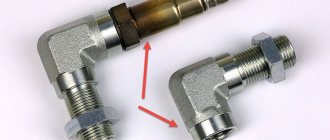
- Up to 1400 rubles - this is for the corner version of the blende.
- Up to 1200 rubles - this is for the second lambda sensor with a metal minicatalyst. Suitable for vehicles with Euro 4 engines.
- 500 rubles is for the most common option, a mechanical blende manufactured by Fort Luft. It does not contain a microcatalyst. Installed on cars up to 2001.
Which lambda decoy is better?
Unambiguously answer the question “Which lambda decoy is better?” impossible. Each device has its own pros and cons, and different compatibility with certain models. Which lambda probe decoy is best installed depends on the purpose of this manipulation and specific conditions:
- mechanical blende operate only in conjunction with a working oxygen sensor;
- To simulate the normal operation of an oxygen sensor on an old gas equipment, only electronic fakes with a microcontroller (pulse generator) are suitable;
- on old cars of a class no higher than Euro-3, it is better to install a screw-in screw - cheap and reliable;
- on more modern cars (Euro-4 and higher) it is better to use mini-catalysts;
- the option with a resistor and capacitor is a cheaper, but less reliable type of blende for new cars;
- An emulator of a second lambda probe on a microcontroller, powered by the first one, is the best option for a car with a failed or removed second oxygen sensor.
Generally speaking, a mini-catalyst is the best option for a working DC, because it highly reliably imitates the operation of a standard converter. A microcontroller is a more complex and expensive option, and therefore is only appropriate when there is no standard sensor at all or it needs to be tricked to drive on gas.
Possible consequences
This method of fooling a car computer is a risky endeavor. The following may happen:
- Failure of all sensors without the right to restoration.
- Many different errors can appear in the on-board computer.
- Wiring problems.
- The engine may malfunction because when the computer should give a signal - to supply a rich mixture or, conversely, a lean mixture, but it will not do this, because the snag shows that everything is normal.
Replace lambda probe
If the oxygen sensor is faulty, there are several options to solve the problem. One of them is to change the lambda probe sensor. You can do this yourself by purchasing a new part in a specialized store or car service center. Pay attention to the markings on the old probe. The new probe should have exactly the same one.
Replacement must be done with the engine cooled and the ignition off. To begin with, the wires are disconnected from the old device. Then the old probe is disconnected with a wrench and a new one is put in its place. You must work carefully, without breaking the thread.
If you are not sure that you can handle it, contact a specialist. Where can a lambda probe be replaced? In any car service for little money. Specialists will do the job efficiently. For the next 50,000–100,000 km, the original oxygen sensor will work perfectly.
Benefits of Installing a New Oxygen Sensor
- Saves fuel from 5 to 15%. A worn sensor affects fuel consumption, so installing a new one will return it to normal;
- Improves engine performance;
- Notifies with 100% certainty that the catalyst is failing;
- Reduces the release of harmful substances.
A significant disadvantage of this solution is the price. The cost of a new lambda probe reaches 25,000 rubles. If the car's catalyst is disabled or knocked out, replacing the lambda probe will not help. Software shutdown will help - chip tuning.
Tips and tricks
As you can see, a catalytic converter error can be a real problem for the owner, and a large amount of money is required to replace the catalytic converter on the car.
Of course, you can install a lambda trick, but you should remember that this solution is not always possible to integrate well, especially on “fresh” cars. For this reason, it is advisable to follow certain rules to increase the service life of the catalyst.
We also recommend reading the article about why engine speeds fluctuate when hot. From this article you will learn about the main reasons for floating speed after warming up the internal combustion engine, as well as methods for diagnosing and solving this problem.
First of all, it is important to understand that bad fuel can damage the catalyst. You should only refuel at proven gas stations, and also fill in gasoline of the brand recommended by the car manufacturer itself (for example, you cannot pour cheaper AI-92 gasoline into a car where the use of AI-95 or AI-98 fuel is allowed.)
Secondly, you should not actively pour various fuel additives into the tank, especially from little-known manufacturers. The effect may be questionable, and the damage to the catalyst may be great.
Third, any mechanical impact on the catalyst should be avoided (during car repairs and when operating the car). The fact is that the ceramic honeycomb of the catalyst is very fragile and can crumble even during aggressive off-road driving.
You also need to drive through puddles and snow piles carefully, since in this case the highly heated catalyst quickly cools. Such temperature changes can quickly destroy the fragile honeycomb of the catalyst.
Catalyst care
The ecology of our planet does not respond well to such tricks, so it is better to purchase and install new parts if they fail. Think of the emulator as a temporary solution and try to avoid catalytic converter failure.
- give preference only to high-quality fuel;
- avoid deep puddles so that the heated catalyst is not subjected to sudden cooling;
- refuse questionable fuel additives from unknown manufacturers;
- undergo regular maintenance;
- Avoid mechanical damage to the housing.
Bottom line
Before doing something on your own, you should always sensibly assess your strengths; if you are confident, then go ahead, if you still are not, then you should turn to the experts. Yes, at the service station you will most likely not be given guarantees about continued performance after unscrewing the lambda, but it’s still worth contacting a service center where professionals will install either mechanical or electronic decoys, or in extreme cases, firmware and configuration specialists will download a new one program code for your ECU.
- Next Contract engine: what is it and how to choose
- Back Brake pedal beating: what to do if it happens
- Engine/Ratings
Aug 23, 2019
- Hyundai crossovers / News
Aug 23, 2019
- Aug 22, 2019
- Volkswagen crossovers / News
Aug 21, 2019
- Crossovers Ford / News
Aug 20, 2019
- Audi crossovers / News
Aug 20, 2019
- April 13, 2019
- March 12, 2019
- Feb 17, 2019
- April 11, 2019
- July 27, 2017
Mechanical options for decoys
Mazda tribute
The problem can be solved using two types of deceptions.
When choosing a mechanical type of emulator, a spacer made of bronze or other metal that is not afraid of elevated temperatures is installed in place of the catalyst. The size of the emulator must match all sizes of the standard catalyst. In the place where the blende is fixed, you need to drill holes through which exhaust gases will be supplied into the cavity of the emulator.
The emulator must contain ceramic chips coated with a catalytic layer, which will cause the oxidation of CO and CH by the oxygen flow. At the output, the level of components harmful to the environment will be significantly reduced.
In addition, the signals from both sensors will be different, so there will be no malfunctions in the operation of the power unit. The presented emulator of a standard catalyst can be positioned as the most budget-friendly. It is noteworthy that mechanical blende is ideal for use with any car.