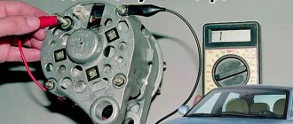
Testing internal elements
Always remember that before testing, the relay must be disconnected from the power source! Even capacitors that are disconnected from the network store an accumulated electrical charge.
Take a multimeter and determine the resistance:
if the contact and pole are normally closed, the resistance will be zero;
if the pole and normally open contact - the resistance is greater than 0.
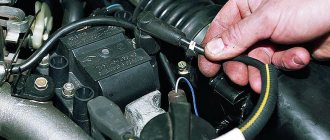
To test the relay acoustically, you need to connect two conductors to contacts 85 and 86. Connect the other ends of the conductors to the battery. You will hear the operating relay immediately - when the conductor and battery come into contact, clicks will appear.
There are clicks, but do the moving and fixed contacts work? Let's find out:
- Take a multimeter and attach its probes to the contacts. If everything is normal, you will hear a whistle.
- If you don't have a multimeter, then you can use a test light. In this case, an additional conductor will be needed. Connect it to the “+” contact and place it on the coil. Connect the second conductor to another contact. We connect the light bulb to “–”. When the relay is turned on, the light should light up.
The cause of non-functioning electrical equipment in the car (for example, fuel pump, heated seats, heated windows, power windows, etc.) may be a faulty relay. Let's look at a simple way to test a car relay for functionality with your own hands.
Connection diagram for 4 and 5 contact relays:
Symptoms of problems
How can you even determine that the horn is not working or has some kind of malfunction? It's actually extremely simple.
There are 2 main signs of problems with a car horn:
- The signal doesn't work at all. When you press the button, the driver, like other road users, hear absolutely nothing. This is a clear indication that the system has failed;
- The signal appears periodically. There is also a slightly different situation when the horn does not go off with every press. That is, they pressed it once, everything works, but when you try to honk again, the horn goes silent, there is no reaction to the press. Then the situation repeats itself.
There is nothing complicated or unusual in determining the nature of the malfunctions. But now we need to understand why this happens and where to look for the reasons.
Design and principle of operation of the switching device
An electrical relay is a part that is used as a switch thanks to the control signals that are supplied to it through an electrical circuit. The line connected to the device is called controlled; the line through which a command is already being sent to it - the manager.
It is used in domestic conditions and in all industries to automate various operations. If a household or electrical appliance fails, you must first check the functionality of the switching element. But first it is recommended to familiarize yourself with the types and operating principles of relays.
Principle of operation
The part is an electromagnet, which includes an inductor, an armature and a contact group.
Each component is mounted on a base and enclosed in a protective housing. The armature is located on top of the magnetic system core; in the initial position it is held thanks to a spring, which has the shape of an L-shaped movable plate.
The lower part of the base is equipped with a contact group; on the contrary, the same number of contact bases is mounted. The contacts are ductile because they need to be brought out outside the protective housing to form the device terminal.
The principle of operation of the relay is based on its ability to influence conductive objects with its electromagnetic field. As soon as voltage is applied to the winding terminals, current begins to flow through the relay. When its value reaches a previously programmed value, two forces are formed in the winding, which press the armature to the surface of the coil.
Taking into account the design features, the initial position can be not only closed, but also open. In the second case, when voltage is applied, the line will open. The contacts of the device will return to their original state as soon as the signal of the required magnitude is removed from the relay terminals.
Device
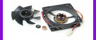
General structure of the windshield wiper system:
- As everyone knows, the wipers are driven into a state of “swinging” of varying speeds by an electric motor, which has a built-in gearbox, and the motor runs on direct current. Three brushes are “built-in” in the motor armature, with the help of which the VAZ 2110 wipers operate in three modes. There are only two speed frequencies: one for fast movement (for example, during a rainstorm), the second for slow or intermittent movement;
- The electrical component is the switch (under the steering wheel); relay switching on intermittent mode; additional relay; switch. The entire electrical system is connected by wires (in blocks) through a thermal bimetallic fuse. Moreover, both one and the other relay, as well as fuse F5, are located in the mounting part, and a bimetallic fuse with a limit switch is located in the electric motor gearbox;
- Directly windshield wipers. Their size is important, as well as the material, shape, and device. Check whether the already installed ones squeak, whether the mechanism and the leash are working, perhaps they need improvement;
- Mechanics. First of all, this is a drive that can break.
Wiper diagram for VAZ 2110
Types and characteristics
Depending on the element base used, relay regulators are divided into the following types:
- Microcontroller or microprocessor based. Their peculiarity lies in the inclusion of a working algorithm in the built-in chip. Used in expensive cars, such as BMW or Audi.
- Relays are based on switching relay contacts to cut off and stabilize the performance of the electrical network.
- Integrated relays are widely used in the automotive industry. The operating principle is based on solid-state switching parts or integrated semiconductors.
- Hybrid transistor-relay devices and simply transistor ones are based on semiconductor elements. They were actively used in industry until the early 90s.
Do-it-yourself repair of direction indicators and hazard alarms
If the turns disappear, as well as the car’s emergency signal, then you can try to solve this problem yourself:
- If the safety element and relay break down, the failed parts must be replaced. If the reason lies in a short circuit, then before replacing it is necessary to check all electrical circuits in which it could occur. Only after the cause of the short circuit and power surges has been eliminated, the devices need to be changed.
- If the hazard warning button is faulty, you just need to replace it. We have already talked about how to diagnose this part.
- As for electrical circuit diagnostics, it is carried out using a tester. If damaged sections of the wire are identified, they must be replaced. When laying them, make sure that the wiring does not come into contact with moving body elements. It is also recommended to additionally insulate new wires to increase the reliability of the insulation.
- If the reason is the light bulbs, then all burnt out light sources must be replaced. In the front and rear headlights, the lamps are changed by removing the protection from the headlights, disconnecting the power circuit from the lamp, as well as unscrewing the light source from the seat and replacing it with a new one. If the lamps in the side headlights do not work, then, as a rule, to dismantle the lighting sources, the lamp itself must be pryed off with a screwdriver, then disconnect the power cord and remove the device.
- If the reason lies in the steering column switch, then this device needs to be disassembled and checked. As a rule, the cause of switch failure is poor contact or abrasion. In this case, the failed switch is replaced with a new one. As for the contacts (no matter where - on connections or buttons), it is advisable to clean them.
- You should also check all the plugs and connectors, because it is quite possible that the problem is poor contact on them. Acidified contacts must be cleaned with a wire brush or sandpaper. If the contacts are burnt out, they will need to be replaced.
Symptoms of a problem
Before checking the relay with a multimeter, you should familiarize yourself with the main signs that the part has failed.
- There are cases when, as a result of the failure of the voltage regulator, the battery boils.
- When the ignition is turned on, the control light on the dashboard does not light up (however, this can be a symptom of other types of malfunctions, for example, a contact has fallen out or burned out).
- The dynamic characteristics of a household appliance or car are reduced, especially when the engine reaches high speeds.
- After starting, the battery indicator does not go out on the dashboard, which indicates a battery problem.
- The indicators on the dashboard simply turn off if the engine speed during operation exceeds 2000 rpm.
- The brightness of the headlights depends on the engine speed. It is quite simple to verify this - you need to stand in front of the wall in the dark and turn on the headlights. The brightness of the glow will change depending on how hard you press the gas.
- The battery is regularly discharged.
These signs may indicate other malfunctions, but first of all it is recommended to check the relay regulator.
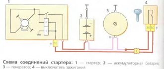
Application in car
Most often motorists have to deal with switching devices. We are talking about the generator (starter) regulator relay. They remember it when the engine stops starting and it turns out that the battery is discharged. One of the reasons for this is a malfunction of the regulator.
On older cars, to maintain a constant voltage, a regulator was used, consisting of three devices - a voltage stabilizer, a current limiter and a reverse current relay. The regulator prevents the battery from overcharging, which prolongs its service life.
It can be built into the starter brush block or performed as a separate module. Its failure may or may not overcharge the battery. In the first case, streaks will be visible on the case, the electrolyte will begin to boil away, which will lead to a voltage drop below 12 volts. In the second, the values will initially be lower than acceptable. As a result, the engine will not start.
Reasons for failure of the relay regulator
In order to minimize the likelihood of repeated breakdowns in the future, you should familiarize yourself with the main reasons for device failure.
- Short circuit in any part of the electrical circuit, including interturn short circuit of the excitation winding.
- The regulator may also fail if the diodes break down or the rectifier bridge breaks down.
- Incorrect connection or reverse direction to the battery terminals.
- Penetration of moisture or large amounts of dust into the generator and/or the regulator itself (such cases are common during heavy rainfall or when washing the car).
- Mechanical damage to the working unit.
- Natural wear and tear, end of service life.
- Initially, the quality of the purchased product is questionable.
No sound
Neither signal makes any sound other than a squeak? Then the problem lies somewhere in the wiring. Now is the time to check the fuse, which is most likely hidden deep down in the dash, driver's side dash, or under the hood - or just about anywhere in the front half of the car if it's not in one of the obvious places. Find the location of the fuse box and special fuse in the owner's manual.
Inspect the instrument panel cover or check your owner's manual to determine which fuse protects the signal circuits. If the S-shaped strip is broken (fuse on the right), replace the fuse.
If the metal strip inside the fuse appears to be broken, replace it with another of the same amperage rating. It is very rare, but fuses fail for no apparent reason. If the fuse is bad, chances are you have a problem that will cause it to blow again, sooner or later.
Preparing to test the relay for functionality
Checking the relay will not take much time if all the preparatory work is done correctly.
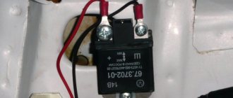
Before you begin diagnosing the device, you need to determine the purpose of the pins of the part being tested. To do this, use the documentation supplied with the device; it contains all the diagrams and operating features, and the characteristics of the device.
There are common cases when the operating diagram is depicted on the relay body itself. Contacts are represented by dots; they are connected by an inductor, the switching elements are straight lines with a dotted line. The power supply pins are shown schematically as a rectangle.
If the relay is built into the circuit, you need to visually inspect the state of the bus and power traces on the board itself. To check the relay with a tester, you can use both digital and analog instruments. No preliminary preparation or setup of testers is required.
In addition to the tester, you need to prepare a regulated power supply. For the results to be reliable, the relay must be removed from the circuit.
The functionality test is carried out in several stages:
- winding;
- normally closed position;
- normally open state.
Then you can proceed directly to diagnosing the relay.
Video
You can watch the relay testing process in detail in the video.
But you can learn about how to check the wiring in a car for a short circuit or break in other useful articles on our website.
A relay is a device designed to control high power signals with low power signals. Its main task is to separate and protect the low voltage circuit with an electromagnetic coil from the high voltage circuit. There are several ways to verify that the relay is working; the most convenient, fastest and most reliable is to use a multimeter.
Diagnostics of windings and contact groups
The winding is an inductance coil on which wire is wound in a spiral.
It is characterized by a certain resistance, which is calculated according to Ohm's law. The resistance value should range from 10 to 100 Ohms. Diagnostics of the winding allows you to find out whether its integrity is compromised. Functionality testing is carried out in several stages:
- The multimeter is turned on in resistance testing mode. On the instrument panel this mode is indicated by the symbol – Ω, the range is set within 2 kOhm.
- One measuring wire is connected to the socket, and the second to the COM.
- The wire probes touch the relay terminals.
The resistance of the inductor can be determined by the deflection of the arrow.
Checking contact groups is carried out in two stages. First, the resistance must be measured offline, and then when voltage is applied to the coil. When checking, you will need a power source, you need to take care of this in advance.
Operating principle
Essentially, a relay is an electromagnet. When control voltage is applied to the coil, the rod attracts the armature, thus switching the circuit.
There are three types of relays:
- with normally closed contacts;
- with normally open;
- throwing over.
When a control signal is applied to a device with normally closed connectors, they open; if there is no signal, they close. For relays with open connectors, the opposite is true. There is voltage on the winding, the terminals close, but when there is no voltage, it opens. In flip-over models there are two sets of connectors, one normally closed and the other normally open. They have a common terminal. When current is applied to the winding, the contacts switch from one position to another.
Abnormal voltage readings on the multimeter
If the multimeter shows low voltage in the battery, the battery will simply stop accepting charge. As a result, the car may not start, the indicators on the dashboard may stop working, and troubles may arise while driving.
If the voltage is increased, there is a possibility that the level of electrolyte in the battery bank has decreased, or it has simply boiled away. Another characteristic feature may be the formation of a white coating on the walls of the body. When recharging, the battery may begin to behave unpredictably.
It's time to stop
In fact, expressing your displeasure by beeping is completely inappropriate. The taxi driver will continue to behave in the same way on the road, regardless of your signal. In cities, it is illegal to use your horn in a residential area unless there is a traffic situation where you really need to do so, otherwise you will face a fine. In general, beeps are not intended to give your teenage son the opportunity to signal to his girlfriend that he has been waiting for her on a date. A short horn will help attract the attention of a pedestrian who steps out onto the roadway without looking around, or of some mother who is driving her children to the section, chatting on the phone and looking in the rearview mirror at her whining offspring.