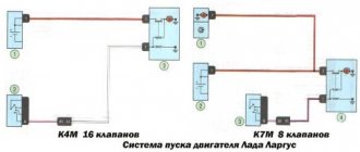
If you have some experience, troubleshooting in the injection engine system of a car can be done “manually”, that is, using a multimeter and based on your own observations of the behavior of the motor.
But performing this task is greatly facilitated by searching for faults and errors in the memory of the ECU (controller), for which purpose a diagnostic connector is installed on cars, including the VAZ 21099.
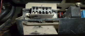
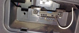
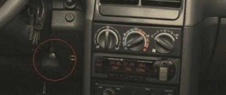
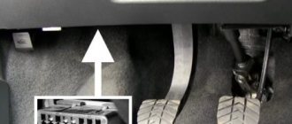
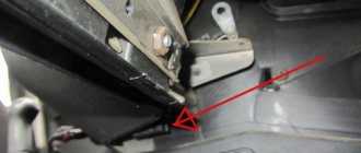
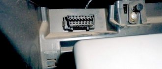
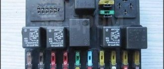
It is attached to the bottom of the shelf under the glove compartment, next to the additional relay and fuse box:
Description of the Autocom program
List of supported ECUs:
- engine diagnostics using the OBD2 protocol - engine diagnostics using factory protocols - diagnostics of electronic ignition systems - diagnostics of climate control systems - diagnostics of immobilizers - diagnostics of transmission control systems - diagnostics of ABS systems - diagnostics of SRS Airbag systems - diagnostics of the dashboard and resetting service intervals - diagnostics of systems ensuring comfort - diagnostics of body electronics systems
The GENERIC diagnostic program is a standards-based diagnostic program specifically designed to link and standardize fault codes. GENERIC is included for car and truck variants.
Protocols and standards 2xHS CAN (ISO 11898-2), SW CAN (SAE J2411), K/L (ISO 9141-2), VPW (J1850), PWM (J1850), RS485 (J1708), TTL and (SPI, analog in, 5volt out).
With the onboard recorder feature, you can record parameters in real time while the vehicle is moving. While recording, you can, with the press of a button, highlight and remember a specific error for the purpose of studying it later. TCS CDP is equipped with built-in memory, eliminating the need for a computer. Memory is not included.
Useful: Pinout of diagnostic connector for VAZ cars
With the Autocom multi-color indicator, you have complete control over the diagnostic process. Different colors and sound prompts will indicate to you which diagnostic stage is currently running. For example, if the indicator switches between blue and green, it communicates with the vehicle's control unit.
When Autocom is connected to a vehicle, the device will check the vehicle's onboard voltage and automatically adjust to the vehicle's 12 or 24 volt voltage level. If the voltage gets too high or too low, Autocom will alert you with both an audible prompt and an indicator light, as well as an alert via the battery icon in the software.
The software has a feature that allows you to read the chassis number from the vehicle you would like to diagnose. This ensures that the model and year are selected automatically. In addition, the engine code for vehicles that are usually available for reading is also automatically selected.
The Intelligent Scanning System (ISS) scans all the systems in the vehicle and displays the fault codes that are stored in each system. This saves time and gives you a quick overview of the current condition of the vehicle as a whole. Once the ISS is completed, you can select a dedicated management system to analyze the results further.
Intelligent System Identification (ISI) detects and automatically selects the type of controller that is installed in the vehicle. This ensures that the diagnostic session is completed correctly with the correct parameters as required.
According to this feature, you will be able to see the adaptations and adjustments that are possible for a particular vehicle without having the vehicle near you. Together, using the texts as a guide, you can plan and be effective in your work, even in difficult situations.
The Autocom car scanner is equipped with a unique multiplexer technology, which allows it to be used on all types of vehicles, regardless of voltage level and communication standards. For those vehicles that do not use a standard 16-pin connector, it is possible to connect special adapter cables.
Diagnostic modes, OBD protocols for VAZ cars
The OBD standard has five types of information exchange protocols:
- CAN type;
- KWP2000;
- ISO 9141 version 2;
- J1850 VPW and PWM.
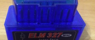
The purpose of OBD is to harmonize the various electronic systems of the car and ensure the exchange of information between devices. The standard establishes a number of rules for the transmission of data packets. The exchange speed is individual for each protocol. The ELM327 adapter coordinates the ECU and external devices for reading information. The data is displayed to the user in an accessible form.
The fastest is the CAN bus. The latest Zhiguli models provide for the use of this standard. Other protocols on this family:
- ISO 9141;
- K, L lines;
- K, L lines (extended block 55 pins).
Note: the number of supported diagnostic and interrogation modes of on-board systems depends on the installed protocol. The owner needs to check the year of manufacture and model of the standard control unit before servicing. The more recent the ECU and its firmware, the wider the list of available scanning parameters.
Important:
Some ECUs do not support the full set of functions without the use of a dealer scanner.
Select the car model and year of manufacture to determine which diagnostic modes your car supports through the ELM327 adapter, as well as what protocol the OBD2 port is based on. The data is presented for the following VAZ models and their modifications: 2114, 2107, 2110, 2112, 2109, 2115, 2106, 2108 and others.
Note:
(1) — The numbers between brackets (x3) correspond to the number of vehicles of the same type
(2) - DIN horsepower (multiplied by 0.736 for kW power)
(3) - PID is only supported for the primary oxygen sensor (#1)
- Mode X Column: A vehicle showing 00000000 in a mode means that the corresponding PID is not active and that as a result the mode is maintained but does not respond to any requests. None of the vehicles described below support Mode 8.
- Energy column: fuel type, Die for diesel, Pet for gasoline, Hyb for hybrid
- The vehicles on this list are classified alphabetically by make, model, then in order of increasing horsepower.
Mode 1
This mode returns common values for some sensors, such as:
- engine speed;
- vehicle speed;
- engine temperature (air, coolant);
- information about oxygen sensors and air-fuel mixture.
Mode 2
This mode provides a freeze frame (or instantaneous) failure data. When the ECM detects a malfunction, it records sensor data at the specific point in time when the malfunction occurs.
Mode 3
This mode displays stored diagnostic trouble codes. These fault codes are standard for all car brands and are divided into 4 categories:
P0xxx: for standard transmission related faults (engine and transmission) C0xxx: for standard chassis faults B0xxx: for standard body faults U0xxx: for standard communication network faults
More detailed information and definitions of common trouble codes are available on the OBD Common Trouble Codes page.
Mode 4
This mode is used to clear stored trouble codes and turn off the engine malfunction indicator.
Note: There is generally no need to repair a problem that has not been diagnosed or corrected. The MIL will illuminate again during the next driving cycle.
Mode 5
This mode provides the results of self-diagnosis performed on the oxygen/lamda sensors. This mainly applies only to gasoline vehicles. For new ECUs using CAN, this mode is no longer used. Mode 6 replaces features that were available in Mode 5.
Mode 6
This mode provides self-diagnosis results performed on systems that are not subject to constant monitoring.
Mode 7
This mode produces unconfirmed fault codes. After repair, it is very useful to check that the fault code does not appear again, without having to perform a lengthy test run. The codes used are identical to those in mode 3.
Mode 8
This mode provides self-diagnosis results on other systems. It is unlikely to be used in Europe.
Mode 9
This mode gives vehicle information such as:
- VIN (vehicle identification number)
- calibration values
Mode 10 (or Mode A)
This mode gives permanent error codes. The codes used are identical to those in modes 3 and 7. Unlike modes 3 and 7, these codes cannot be cleared using mode 4. Only a few road cycles without the problem occurring can clear the fault.
If you have some experience, troubleshooting in the injection engine system of a car can be done “manually”, that is, using a multimeter and based on your own observations of the behavior of the motor.
But performing this task is greatly facilitated by searching for faults and errors in the memory of the ECU (controller), for which purpose a diagnostic connector is installed on cars, including the VAZ 21099.
It is attached to the bottom of the shelf under the glove compartment, next to the additional relay and fuse box:
Depending on the operating protocol, pinout options are allowed:
When using the standard ISO 9141-2 protocol, it is activated via pin 7, while pins 2 and 10 in the connector are inactive. For data transmission, pins numbered 4, 5, 7 and 16 are used (sometimes pin number 15 can be used).
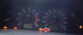
Error code: How the rear wiper works on the Lada Vesta