The diagnostic connector of a Priora car is a plug, by connecting to which you can identify 80% of breakdowns related to electronics. Of course, the diagnostic plug will not show whether the valve is bent or whether the pump is worn out, but believe me, it knows and can do a lot. Knowing this, car thieves take advantage of this. It’s very easy to steal any modern car, be it a Priora or an Infiniti, if you know where this connector is located.
The presence of a diagnostic connector on the Priora OBD is a vital necessity. In a modern car, it is often impossible to just look under the hood and immediately determine the problem. This is explained by the fact that the operation of all components of the car is coordinated by an electronic control unit - a small computer with which you need to find a common language.
You will have to use the diagnostic connector of a Lada Priora car at least once during its operation. Before buying a connector, you need to find out more about where the connector is located, how it is designed, what it is needed for, and what operation can be used to secure the Priora from theft. Read the article to the end and we will talk about the topics: diagnostic plug pinout, anti-theft protection, where to find it!
Do-it-yourself diagnostics
Various breakdowns of sensors and other devices can cause increased gasoline consumption, incorrect engine operation, and increased wear of car system components. Despite the presence of errors, the VAZ Priora will drive until the driver has to make expensive repairs because of them.
VAZ Priora car
So that the motorist does not suddenly have to face the need for repairs, a special controller is installed on the VAZ Priora, with the help of which the driver can diagnose breakdowns. This can be done either using special additional equipment or an on-board computer installed in the car.
In fact, to carry out diagnostics, the car owner will only need to press a few buttons and count combinations of faults.
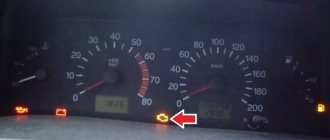
For example, you do not have a special tester, so we will look at diagnosing the vehicle for errors using the on-board computer. The BC is built into the dashboard and can be used to read combinations of faults. To do this, you need to activate the auto test mode.
The arrows on the dashboard move to maximum values when performing self-diagnosis of the vehicle
- First, turn off the ignition. After this, hold down the daily mileage reset button and turn on the ignition. Please note: the button must be held down.
- There is an LCD indicator on the vehicle's dashboard, keep an eye on it. When you turn on the ignition, all icons will begin to light up, and all arrows (speedometer, tachometer, antifreeze temperature sensor, gasoline level status) will begin to move to the maximum values and back. That is, if all the arrows behave as described here, this means that the sensors and indicators are functioning correctly.
- Now you need to find the button for switching BC functions - it is located on the right steering column switch. By clicking on it, the software version (1.0 and higher) will be displayed on the screen.
- Click on this button again. Combinations of faults will begin to appear on the screen. If necessary, you can reset error data here. To do this, press and hold the daily mileage reset button for about three seconds.
The appearance of a fault combination on the LCD screen during self-diagnosis
Refinement of the VAZ 2110 OBD connector: independent connection of the elm 327 adapter
There is a special “CheckEngine” light on the dashboard of the VAZ 21110 car. When the ignition is turned on, the light comes on and while the vehicle’s internal combustion engine is not running, a special program reads data from all units and systems of the vehicle, transmitting data on fault detection to the on-board computer.
If, after starting the vehicle’s internal combustion engine, the “check” does not go out for another 10 seconds, it means that faults in the system have already been identified and the corresponding error codes have been entered into the memory of the on-board computer.
VAZ 2110 cars are equipped with a “January-4” controller, which does not provide feedback and the “check” lights up and there is a fault detection signal. Error codes in such a controller are calculated starting from “12” and ending with “61”.
The codes are deciphered either with a special diagnostic device or independently. Using the example of the VAZ 2110 “January-4” ECU, we will consider the algorithm for performing diagnostics independently:
- connect contact “B” of the diagnostic block and “ground”;
- turn the ignition key to the third position without starting the car;
- the “CheckEngine” light illuminates the code “12” (the light flashes once -1, after a pause of two seconds it flashes twice in a row -2 flashes three times in a row (the program has started diagnostics);
- the program will detect the malfunction by displaying the corresponding error codes (flash, pause).
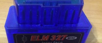
Some tips for installing a modern ELM 327 adapter with the OBD-II program (protocol) for the VAZ 2110:
- purchase an adapter along with a cable;
- study the installation instructions (pinout of the block and location of each connector);
- You must insert your own cable into each connector of the block, checking the pinout; it must comply with the manufacturer’s instructions.
Let us also add that programs for determining faults of the ELM 327 adapter are downloaded from various sources on the Internet.
Diagnostic connector for Lada Priora
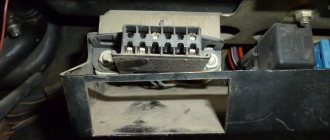
Modern cars, in the event of malfunctions in the operation of the engine or its systems, store errors in the memory of the electronic control unit (ECU). There is a special connector to connect it to diagnostic equipment in the car. The Lada Priora uses a standard European OBD-II connector.
Diagnostic connector Lada Priora OBD 2
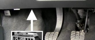
Diagnostic connector location
Diagnostic connector location
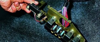
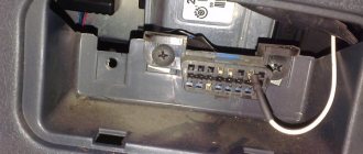
On Lada Priora cars, the diagnostic connector is located behind the glove compartment (glove box) on the rear wall on the left side. To gain access to the connector, open the glove compartment. Then disengage the glove box latches and lower it down.
Assignment of diagnostic block contacts
Assignment of diagnostic block contacts: 2 - J1850 Bus 4 - Chassis Ground 5 - Signal Ground 6 - CAN High (J-2284) 7 - ISO 9141-2 K Line 14 - CAN Low (J-2284) 15 - ISO 9141-2 L Line 16 - Battery Power
After reading the error codes, they are deciphered using the table:
Kalina/Priora on-board computer errors:
0102 Low level of mass air flow sensor signal 0103 High level of mass air flow sensor signal 0112 Low level of intake air temperature sensor 0113 High level of intake air temperature sensor 0115 Incorrect signal of coolant temperature sensor 0116 Incorrect signal of coolant temperature sensor 0117 Low level of temperature sensor coolant 0118 Coolant temperature sensor signal high 0122 Throttle position sensor signal low 0123 Throttle position sensor signal high 0130 Oxygen sensor signal 1 incorrect 0131 Oxygen sensor signal low 1 0132 Crankshaft sensor signal high 1 0133 Slow response oxygen sensor 1 0134 No signal from oxygen sensor 1 0135 Malfunction of oxygen sensor 1 heater 0136 Short circuit to ground of oxygen sensor 2 0137 Low level of oxygen sensor 2 0138 High level of high signal of oxygen sensor 2 0140 Open circuit of oxygen sensor 2 0141 Malfunction of oxygen sensor 2 heater 0171 Too lean mixture 0172 Mixture too rich 0201 Injector 1 control circuit open 0202 Injector 2 control circuit open 0203 Injector 3 control circuit open 0204 Injector 4 control circuit open 0261 Injector 1 circuit short to ground 0264 Injector 2 circuit short to ground 0267 Injector circuit short to ground sunki 3 0270 Short to ground in the injector 4 circuit 0262 Short to 12V in the injector 1 circuit 0265 Short to 12V in the injector 2 circuit 0268 Short to 12V in the injector 3 circuit 0271 Short to 12V in the injector 4 circuit 0300 Many misfires 0301 Misfires in cylinder 1 0302 Misfire in cylinder 2 cylinder 0303 Misfire in cylinder 3 0304 Misfire in cylinder 4 0325 Open circuit of knock sensor 0327 Low level of knock sensor signal 0328 High level of knock sensor signal 0335 Incorrect crankshaft position sensor signal 0336 Crankshaft position sensor signal error 0340 Phase sensor error 0342 Neither low signal level phase sensor 0343 High signal level of the phase sensor 0422 Low efficiency of the converter 0443 Malfunction of the canister purge valve circuit 0444 Short circuit or break in the canister purge valve 0445 Short to ground of the canister purge valve 0480 Malfunction of the cooling fan circuit 1 0500 Incorrect speed sensor signal 0501 Not correct speed sensor signal 0503 Interrupt speed sensor signal 0505 Idle speed control error 0506 Low idle speed 0507 High idle speed 0560 Incorrect on-board power supply voltage 0562 Low on-board power supply voltage 0563 High on-board power supply voltage 0601 ROM error 0603 External RAM error 0604 Internal RAM error 0607 Knock Channel Malfunction 1102 Low Oxygen Sensor Heater Resistance 1115 Faulty Oxygen Sensor Heater Circuit 1123 Rich Idle 1124 Lean Idle 1127 Rich Partial Load 1128 Lean Partial Load 1135 Oxygen Sensor Heater Circuit 1 open, short circuit 1136 Rich mixture in Light Load mode 1137 Lean mixture in Light Load mode 1140 Measured load differs from calculation 1171 CO potentiometer low level 1172 Potentiometer CO level high 1386 Knock channel test error 1410 Canister purge valve control circuit short circuit to 12V 1425 AD purge valve control circuit sorber short short to ground 1426 Control circuit of the canister purge valve open 1500 Open circuit of the control circuit of the fuel pump relay 1501 Short to ground of the control circuit of the fuel pump relay 1502 Short circuit to 12V of the control circuit of the fuel pump relay 1509 Overload of the control circuit of the idle speed regulator 1513 Circuit of the idle speed regulator short circuit to ground 1514 Idle air control circuit short circuit to 12V, open 1541 Fuel pump relay control circuit open 1570 Incorrect APS signal 1600 No communication with APS 1602 Loss of on-board voltage to the ECU 1603 EEPROM error 1606 Rough road sensor incorrect signal 1616 Rough road sensor low signal 1612 Reset error ECU 1617 Rough road sensor high signal 1620 EPROM error 1621 RAM error 1622 EPROM error 1640 EEPROM Test error 1689 Incorrect error codes 0337 Crankshaft position sensor, short to ground 0338 Crankshaft position sensor, open circuit 0441 Air flow through the valve is incorrect 0 481 Cooling fan circuit malfunction 2 0615 Starter relay circuit open 0616 Starter relay circuit short circuit to ground 0617 Starter relay circuit short circuit to 12V 1141 Malfunction of the oxygen sensor 1 heater after the converter 230 Malfunction of the fuel pump relay circuit 263 Malfunction of the injector driver 1 266 Malfunction of the force driver nki 2 269 Malfunction of injector driver 3 272 Injector driver fault 4 650 CheckEngine lamp circuit fault
Error code: Where is the obd connector on the Datsun?
OBD 2 pinout
Pinout of the Lada Priora comfort block
The layout and purpose of the contacts in the OBD 2 connector are determined by the standard.
Numbering of plugs in the connector
General description of plugs:
- 1 - reserve, this pin can output any signal that the car manufacturer sets;
- 2 - channel “K” for transmitting various parameters (can be designated as J1850 bus);
- 3 - similar to the first;
- 4 — grounding of the connector to the car body;
- 5 — diagnostic adapter signal grounding;
- 6 - direct connection of the CAN bus contact J2284;
- 7 — channel “K” according to ISO 9141-2 standard;
- 8 - similar to contacts 1 and 3;
- 9 - similar to contacts 1 and 3;
- 10 — pin for connecting the J1850 standard bus;
- 11 — pin assignment is set by the vehicle manufacturer;
- 12 - similar;
- 13 - similar;
- 14 - additional pin of CAN bus J2284;
- 15 — channel “L” according to ISO 9141-2 standard;
- 16 - positive output of the on-board network voltage (12 Volts).
An example of a factory OBD 2 pinout is the Hyundai Sonata, where pin 1 receives a signal from the anti-lock braking system control unit, and pin 13 receives a signal from the control unit and airbag sensors.
Depending on the operating protocol, the following pinout options are possible:
- When using the standard ISO 9141-2 protocol, it is activated via pin 7, while pins 2 and 10 in the connector are inactive. For data transmission, pins numbered 4, 5, 7 and 16 are used (sometimes pin number 15 can be used).
- With a protocol type SAE J1850 in the VPW version (Variable Pulse W >
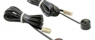
How to remove and check the sensor
Access from above to the Priora DD is difficult due to the intake module located above it. The easiest way to get to the sensor is from below, first removing the engine protection or at least unscrewing and folding its front part. When working from above, you will have to do everything by touch. In any case, before starting work, it is necessary to disconnect the ground wire attached to the “negative” terminal from the battery.
To remove the crankcase protection, you need to:
- unscrew 5 nuts with a 10mm head;
- unscrew the 2 19 nuts installed on the back of the shield;
- remove protection.
- by pressing the metal latch of the DD connector, disconnect the block of wires going to the controller;
- using a 13mm wrench, loosen the bolt securing the sensor;
- Unscrew the bolt and remove it from the threaded hole, removing the sensor.
- We connect a multimeter to the DD terminals. We set the device to voltmeter mode, choosing a measurement limit of up to 200 mV.
- We take a metal object - pliers or a bolt - and lightly tap it on the DD.
When you tap on a working sensor, the voltmeter will show voltage surges. A faulty DD will not react in any way. A more accurate diagnosis of a removed sensor can only be done using a special stand.
Installation of a new DD is carried out in the reverse order of dismantling. Experts recommend installing a similar Bosch instead of the “native” one. Before going to the store for a new sensor, you should write down the markings of the removed sensor. Tightening the bolt securing it to 13 should be done with a slight force - 10.4–24.2 N m (1.1–2.5 kgf). Tightening too tightly will affect the operation of the sensor.
Problems with engine detonation can occur due to various faults. They are often associated with the operation of the electrical circuit from the knock sensor to the electronic control unit, or with the knock sensor itself. The diagnostic scanner can detect 4 common knock errors - P0325, P0326, P0327 and P0328.
Error code: elm327 professional on AliExpress - buy online at a good price
Additional signals about the causes of the malfunction (1000)
- 102 – the DC heating resistance has disappeared;
- 115 – circuit failure of the same sensor;
- 123/124 - violation of mixture formation in the absence of load - idle is acting up;
- 127/128 – duplicates the previous signal in partial load mode – jerks, dips or jerks when pressing the gas pedal lightly;
- 135 – open circuit or short circuit of circuit DK1;
- 136/137 – violation of the formation of a combustible mixture at minimum load;
- 140 – potential difference between measured and actual load;
- 171/172 – incorrect operation of the potentiometer;
- 386 – incorrect detonation channel test result;
- 410/425/426 – short circuit to the sides or ground/break in the lines of the canister purge valve;
- 500/501/502 – open circuit with short circuit of the fuel pump for ground and 12V, respectively;
- 509 – overload of the XX regulator;
- 513/514 – short circuit of the throttle position in position XX;
- 541 – there is no power to the fuel pump or the integrity of the housing may be damaged with fuel getting inside;
- 570 – an incorrect signal from the APS design is received;
- 600 – no impulse is received from the APS; there may be a breakdown or the unit is coming off;
- 602 – 12V short circuit to the electronic engine control unit;
- 603 – problems with the firmware, can be resolved by rebooting;
- 606/616 – interruptions in the operation of the rough road sensor;
- 612 – incorrect ECU reset code – the system did not reboot;
- 617 – the rough road sensor has died or a short circuit has formed;
- 620 – critical fault in the EEPROM;
- 621 – critical RAM fault;
- 622 – failure or breakdown of the EEPROM;
- 640 – conflict in checking firmware status;
- 689 - diagnostics showed that all vehicle systems are in order - erroneous codes were displayed.
Error code: JSC "OBD" - Krasnodar - INN/KPP 2312016730/231201001
Lada Kalina 1 and 2 diagnostic connector location
The diagnostic connector is an indispensable attribute of the on-board engine control module in modern cars. Such a socket is also present in the domestic Lada Kalina. The main purpose of the diagnostic connector is to provide connection between the control unit (ECU) and an external reading device (scanner or laptop computer).
This allows owners (and not only Lada Kalina) to independently diagnose the on-board electronic system, as they say, “without leaving home.” Connecting a laptop (or other device) directly to the diagnostic connector is carried out using an adapter, then a specialized program is launched that reads error codes from the ECU memory.
Many car owners are interested in where this connector is located.
Let us repeat, to perform the diagnostic procedure in a Lada Kalina car you will need a set of the following tools:
- laptop or other scanning device;
- adapter (as a fashionable alternative today, owners use a “Bluetooth” connection);
- diagnostic software product.
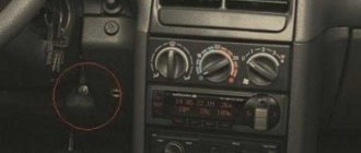
Now you can find the vehicle's diagnostic connector. In the Lada Kalina, its location is in a very suitable place, close to the transmission lever. The socket itself is covered with a plastic cover, which has latches. In the second generation, Kalina has a diagnostic connector, which is located with its own cover, that is, you immediately connect and scan.
Having found the diagnostic connector, we connect it to the adapter. We carry out this manipulation with the ignition off. When the owner of a Lada Kalina uses a wired adapter, then its second edge, equipped with a “USB” connector, is connected to the corresponding socket in the laptop.
We launch the diagnostic software on the device. The program will require drivers. As a rule, they are sold together with the software package (on disk). We switch to the “establish connection” mode. After making sure that the switching has been successful, turn on the ignition and observe. The program begins the diagnostic process.
During the scanning procedure, the engine must be in idle mode. Now we compare each of the obtained parameters with the declared characteristics, which imply the normal functioning of the vehicle systems.
If discrepancies with standard values are observed by more than 20%, then all units or components that indicate such failures are subject to repair, and if this is not possible, replacement.
When the control unit detects an error, the “check engine” symbol lights up on the dashboard. Such a phenomenon should force the owner to perform a diagnostic action. Each error has its own code, the decoding of which can be found on a specialized website on the Internet. The software itself has a corresponding section where these errors can be viewed.
Error code: ELM327 Torque (alternative to pop meter) - All-Russian Automobile Club Mazda CX-7, CX-9
Therefore, when performing a check, we recommend that you carefully monitor deviations from the norm that appear in the functioning of the system.
When to change the timing belt on a Lada Granta 8 valve
Lada Granta timing belt replacement
Replacing the timing belt Lada Granta 8 valves
The diagnostic connector provides greater convenience to the Lada Kalina 2 maintenance process. Once scanning is complete, you can turn off the ignition. After that, in the software menu, select the “break connection” button and disconnect the adapter. The diagnostic procedure is now considered complete.
When you have figured out where the connector is located and connected to it, you can carry out diagnostics. Before the scanning procedure, it is necessary to visually inspect the main components of the car, and then assess their condition.
Diagnostics is aimed at identifying hidden faults in the operation of electronic systems. Using this option, you can evaluate the correct functioning of oxygen sensors, observe the operation of the control unit as a whole, identify and subsequently decipher error codes.
By the way, the errors themselves can be deleted after the diagnostic process is completed.
- Voltage level at the battery terminals (UACC). To check this indicator, you will need to simultaneously turn on all current collectors present in the car. The normal voltage value is at the level of 14-14.5 V. If this parameter is less than the specified value, then a thorough check of the electrical circuits will be required.
- Mass flow of air sucked into the Lada Kalina 2 engine (AIR). The verification process implies the presence of increased engine speeds (up to 5000 rpm). When, with such rotation of the crankshaft, the conventional indicator reaches 220-250 km per hour, the mass air flow sensor can be considered serviceable.
- Injection pulse duration (INJ). Here the discrepancy with the norm is checked in different operating modes of the engine. Idle speed is characterized by fluctuations in the parameter within 3-5 units, and for speeds close to maximum values - 15-20. If these limits are not met, then we are dealing with a problem.
- Oxygen level indicator (ALAM1). It is expressed in the electrical pulse equivalent generated by the corresponding sensor (“lambda”) and is 0.7 Volts. When the specified value is reached, it confirms the fact of stable feedback between the sensor and the unit.
- The number of “steps” generated by the Lada Kalina 2 idle speed regulator (FSM). This indicator reaches 40-60 pulses in idle mode and 150-180 during acceleration.
- Estimated fuel consumption (QT). The parameter contains a set of indicators, to read which you will need special equipment and a professional diagnostician. In independent mode, the owner can scan only one parameter - consumption per unit of time. For idle mode, the figure varies between 0.6-0.9 liters per hour.
VAZ auto electrician on-site
The computer diagnostic service with on-site VAZ (LADA) cars in Moscow is in a hurry to provide immediate technical assistance in any difficult situation on the road. You don't have to waste valuable time moving your car to a car service center. A knowledgeable auto electrician and VAZ (LADA) diagnostician will come to your call point.
We provide roadside assistance and will be useful in:
- auto electrician visit
- repair of immobilizer of any manufacturers
- emergency car opening
- emergency door opening
- opening locks
- light the car
- charge the battery
- computer diagnostics
- troubleshooting
- delivery of gasoline to the site
- electrical repair
- eliminating found problems
- diagnostics of electrical equipment for heated windows
- checking the condition of the electrical wiring
- programming of car control and car alarm units (if necessary)
- replacing broken auto parts
- installation of additional electrical equipment
- It’s not clear, but something is wrong with the car
- other failure variations
Location
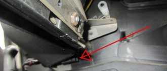
Often faced with a problem where the diagnostic connector is located. In each car they are installed differently, taking into account the specifics of the entire structure. As for Prior, everything here is done quite cleverly. If you don't know the exact location, it will be difficult to find.
Car manufacturers have placed a diagnostic connector in the glove box. You can find it on the passenger side in the interior. Simply put, look in the glove compartment. If you contact service centers, specialists will immediately find the required design. Beginners need to be more vigilant in this matter.
It is best to work according to already compiled instructions. Let's take a closer look at the process:
- We completely open the glove box and clear it of foreign objects to make it easier to work.
- The glove compartment should hang on plastic guides on each side.
- We press on the side plates so that the small door opens further. This will make it easier to work and find the Priora diagnostic connector.
- We pull out the tabs on the side and completely remove the glove box from the latches.
- Provides access to the input plug for diagnostics. Now he is free and ready to go.
Access to the device is open. The following operations directly depend on the purpose of “opening” your car. More often they get to the connector to reconnect it or check the correct signals from the ECU. This way his work will be adjusted and will not create problems or unforeseen situations.
Glove compartment in a Lada Priora car
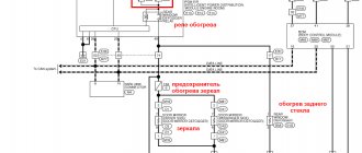
Front Passenger Door Wiring Harness
The electrical wiring of the left and right front doors of the car differs in the additional control buttons for mirrors and power windows on the driver's door.
The factory original front passenger door wiring harness, part number 21703-3724550 -90, duplicates the power supply from the passenger door center front keypad.
There are 7 connectors coming out of the harness.
| Contact no. | Decoding |
| 1 | Connector of the right rear additional harness to the rear harness |
| 2 | Rear left harness connector to front speaker |
| 3 | Window lift motor |
| 4 | Electric window lift switch |
| 5 | electric front passenger door lock |
| 6 | Motor controls the position of the outer right mirror and its heating |
| 7 | Connector of the right rear additional harness to the rear harness |
Deciphering error codes
The Lada Kalina has a diagnostic connector when equipped with a self-diagnosis system, which is now installed on almost all modern cars. The presence of such a connector in cars is due to stricter inspection rules during technical inspections.
Engine diagnostics are carried out to identify hidden problems and defects, as well as to assess the performance of each mechanism.
Diagnostics of Lada Kalina, which can be carried out using a connector.
Diagnosing a fuel-injected car just seems complicated and incomprehensible. Many people believe that this is a matter for trained and experienced craftsmen, but you can check the operation of control systems yourself.
Self-diagnosis begins by connecting the diagnostic tester to the vehicle controller. This makes it easy to obtain diagnostic data and errors. Instead of a tester, you can use a special program by downloading it for free on any suitable resource.
The adapter designed for the connector comes with a special driver and software. The COM port that appears in the program must be rearranged to numbers 1,2, 3 or 4. These are the numbers with which the standard Kalinovsky connector works.
Each engine has its own standard parameters. These are technical characteristics that determine the normal operation of the motor. These parameters are compared with the values obtained during diagnostics. All measurements are carried out with the engine running at idle speed.
- Battery voltage level (UACC). To carry out the test, it is necessary to turn on all the most powerful sources of energy consumption. If the voltage reading on the diagnostic screen is less than it should be, you will have to check all electrical circuits separately. Normal values are from 14 to 14.5 V.
- Mass air flow (AIR). The indicator is determined by the mass air flow sensor. Without diagnostic equipment, checking air flow is impossible. To obtain the value, you need to press the gas pedal until the speed is 5000. If the sensor is working, the indicator rises to a level of 200-250 kg/h.
- Injection pulse duration (INJ). This is the time fuel is injected into the cylinder while each injector is open. Indicators that exceed the norm indicate that the injectors are most likely clogged and clogged. To fix the problem, the parts should be washed. The reasons may also be a clogged fuel filter or a pump failure. To accurately diagnose the problem, press the gas pedal. Normally, the indicators should be from 3 to 5 in a calm, idle state and from 15 to 20 when gasping.
- Oxygen indicator before the catalyst (ALAM1). It should not exceed 0.7 V and, reaching this figure, go back down. This indicates that the feedback is working properly.
- Number of idle speed control (FSM) steps. In other words, the idle speed control sensor. It is a stepper electric motor with a cone-shaped plug attached to the shaft. When the engine is idling, this figure is 40-60 steps, when accelerating - from 150 to 180 steps.
- Estimated fuel consumption (QT). For a complete diagnosis, check the pressure in the fuel rail and the voltage in the spark plugs. It wouldn't hurt to check the compression on the cylinders and find out the CO. However, for all these measurements, in addition to the diagnostic connector and standard equipment, you will need another, expensive device and the connection of experienced professionals. Therefore, here you will have to limit yourself to one indicator: from 0.6 to 0.9 l/hour at idle.
- Throttle Position (THR) value. This parameter is determined by a special sensor. If the throttle position value shows an error and malfunction, the car owner may notice some jerks with “dips” while driving. An increase in the number of idle revolutions will also indicate the presence of a problem. This parameter should be checked with the ignition on, but it is not recommended to start the engine itself. When you gradually press the gas pedal, the readings on the monitor should smoothly increase to 90%. It should be taken into account that it is impossible to achieve 100% - this is predetermined by the manufacturers. The sensor is considered operational if the procedure was successful. Idle speed should show 0%.
- Crankshaft and its rotation frequency (FREQ). The diagnostic figure will be displayed on the screen by a special crankshaft position sensor. The malfunction is easy to notice even without diagnostic equipment, because the engine simply will not start. Indicators from the sensor normally vary in the range from 800 to 840 rpm.
- Limit of uneven crankshaft rotation (LUMS_W). This figure should not exceed 4 rpm. Otherwise, you can be sure that there are misfires in the cylinders. With such a malfunction, it’s time to check the spark plugs and high voltage wires.
- Ignition timing (UOZ). Data from several sensors are combined into one indicator and calculated by the electronic control unit. The value varies from 6 to 15.
- 2 - overvoltage;
- 3 - malfunction of the device indicating the fuel level;
- 4 — the cooling temperature sensor does not work, the circuit may be broken;
- 5 - outside temperature sensor error;
- 6 - probable motor overheating;
- 7 — emergency oil pressure level;
- 8 - the brake system is faulty;
- 9 — battery is discharged;
- E - the error is contained in the data packet.
Paper curtain
When supplying engine oil filters, manufacturers follow industry and government standards. Some characteristics, for example, the opening pressure of the bypass valve, are regulated by technical specifications.
Only companies whose products comply with international standards - ISO 4548 are suitable for the definition of leading brands. The human eye distinguishes hair with a thickness of 70 microns and 40 microns, but in the latter case it is already at the limit of visibility. Without a microscope, a person will not know what bacteria 2 microns in size and soot particles 0.6 microns in size look like.
Curtains of filter elements made of pleated and corrugated paper trap contaminants up to a maximum size of 40 microns. To increase filtration efficiency, synthetics are used.
With a two hundredfold magnification of the structure, you can compare the difference between paper and synthetics (left, right, respectively).
Structure of filter materials
The main differences between paper filters are:
- the presence inside a protective cage that retains pieces of paper when the cartridge is destroyed;
- Curtain ribs can be straight or zigzag, and can have different densities and quantities.
Cassette without protective clip
Zigzag filter fins
Unfortunately, it is almost impossible to see the density and number of curtain ribs through the threaded hole. But when compiling the next rating, experts cut non-separable cases and evaluate the specified parameters, making the information accessible to users.
Is it possible to move the diagnostic connector to another location?
The question often arises in the minds of motorists: can they choose another location for the AR or not? Is it possible to hold such an event on your own? Car owners are interested in this issue, since car thieves know where the DR is located, in particular on the Priora, and are easily able to disconnect it from the alarm.
Let’s say right away: installing a diagnostic connector in another place in the Lada Priora is quite possible, but experienced specialists advise resorting to such a service at a service station. There, qualified employees will carry out the transfer of this part carefully and accurately.
So:
- carefully and accurately disconnect the wires from the connector;
- without haste, remove the device from the socket;
- move the diagnostic connector to the selected location;
- reconnect the connecting wires.
Attention! Experienced experts advise removing the connector yourself next to the gear shift knob or to the left of the steering column.
When another area for AR is selected and the planned manipulation is performed, only you are now aware of where exactly the connector is located. But, note, the hijackers will not be able to react in time to where the area of interest is located.
The diagnostic connector of a Priora car is a plug, by connecting to which you can identify 80% of breakdowns related to electronics. Of course, the diagnostic plug will not show whether the valve is bent or whether the pump is worn out, but believe me, it knows and can do a lot. Knowing this, car thieves take advantage of this. It’s very easy to steal any modern car, be it a Priora or an Infiniti, if you know where this connector is located.
The presence of a diagnostic connector on the Priora OBD is a vital necessity. In a modern car, it is often impossible to just look under the hood and immediately determine the problem. This is explained by the fact that the operation of all components of the car is coordinated by an electronic control unit - a small computer with which you need to find a common language.
You will have to use the diagnostic connector of a Lada Priora car at least once during its operation. Before buying a connector, you need to find out more about where the connector is located, how it is designed, what it is needed for, and what operation can be used to secure the Priora from theft. Read the article to the end and we will talk about the topics: diagnostic plug pinout, anti-theft protection, where to find it!
Questions discussed in the article
Rear door harnesses
The electrical wiring for the rear right and left doors is identical, using only two terminals. The rear door wiring harnesses are factory marked 2170-3724550-10.
| 1 | Block for connection to the rear wiring harness |
| 2 | Rear door lock motor |
Note:
(1) – The numbers between brackets (x3) correspond to the number of vehicles of the same type
(2) – DIN horsepower (multiplied by 0.736 for kW power)
(3) – PID is supported only for the main oxygen sensor (No. 1)
- Mode X Column: A vehicle showing 00000000 in a mode means that the corresponding PID is not active and that as a result the mode is maintained but does not respond to any requests. None of the vehicles described below support Mode 8.
- Energy column: fuel type, Die for diesel, Pet for gasoline, Hyb for hybrid
- The vehicles on this list are classified alphabetically by make, model, then in order of increasing horsepower.
Mode 1
This mode returns common values for some sensors, such as:
- engine speed;
- vehicle speed;
- engine temperature (air, coolant);
- information about oxygen sensors and air-fuel mixture.
Mode 2
This mode provides a freeze frame (or instantaneous) failure data. When the ECM detects a malfunction, it records sensor data at the specific point in time when the malfunction occurs.
Mode 3
This mode displays stored diagnostic trouble codes. These fault codes are standard for all car brands and are divided into 4 categories:
P0xxx: for standard transmission related faults (engine and transmission) C0xxx: for standard chassis faults B0xxx: for standard body faults U0xxx: for standard communication network faults
More detailed information and definitions of common trouble codes are available on the OBD Common Trouble Codes page.
Mode 4
This mode is used to clear stored trouble codes and turn off the engine malfunction indicator.
Note: There is generally no need to repair a problem that has not been diagnosed or corrected. The MIL will illuminate again during the next driving cycle.
Mode 5
This mode provides the results of self-diagnosis performed on the oxygen/lamda sensors. This mainly applies to petrol vehicles only. For newer ECUs using CAN, this mode is no longer used. Mode 6 replaces features that were available in Mode 5.
Mode 6
This mode provides self-diagnosis results performed on systems that are not subject to constant monitoring.
Mode 7
This mode produces unconfirmed fault codes. After repair, it is very useful to check that the fault code does not appear again, without having to perform a lengthy test run. The codes used are identical to those in mode 3.
Mode 8
This mode provides self-diagnosis results on other systems. It is unlikely to be used in Europe.
Mode 9
This mode gives vehicle information such as:
- VIN (vehicle identification number)
- calibration values
Mode 10 (or Mode A)
This mode gives permanent error codes. The codes used are identical to those in modes 3 and 7. Unlike modes 3 and 7, these codes cannot be cleared using mode 4. Only a few road cycles without the problem occurring can clear the fault.