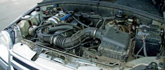
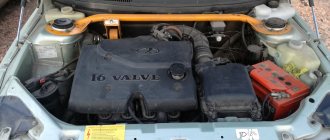
A rather successful development of the domestic automobile industry was the VAZ 2107 engine, which provided 1690 cubic centimeters of displacement. These characteristics allow the power unit to develop a maximum power of 79 horsepower. In this case, the peak torque of the engine is 127 Nm at 3200 rpm.
The VAZ 2107 injection engine was slightly redesigned by the manufacturers, as they added single fuel injection. Thanks to this solution, the inline four-cylinder engine began to work much better, and problems with it arose much less frequently.
Specifications
| Engine capacity, cc | 1690 |
| Maximum power, hp | 79 |
| Maximum torque, N*m (kg*m) at rpm. | 127 (13) / 3200 |
| Fuel used | Gasoline AI-92 |
| Fuel consumption, l/100 km | 6.9 |
| engine's type | In-line, 4-cylinder |
| Add. engine information | single injection |
| Maximum power, hp (kW) at rpm | 79 (58) / 5200 |
| Number of valves per cylinder | 2 |
VAZ 21074 engine control system diagram
Wiring diagram of electrical connections of ECM VAZ 21074 - circuit elements. 1 — controller connector; 2 — mass air flow sensor; 3 — coolant temperature sensor; 4 — crankshaft position sensor; 5 — throttle position sensor; 6 — oxygen concentration sensor; 7 — speed sensor; 8 — ignition module; 9 — solenoid valve for purge of the adsorber; 10 — electric fan relay; 11 — electric fuel pump relay; 12 - main relay; 13 - fuse for the power circuit of the electric fuel pump relay: 14 - fuse for the power circuit of the main relay; 15 — fuse-link; 16-fuse protecting the constant power supply circuit of the controller; 17 - diode; 18 — idle speed regulator; 19 — nozzles; X1 - diagnostic block; X2 - connection block to the vehicle electrical system.
Peculiarities
The VAZ 2107 engine with an injector had a cylinder block made of high-quality cast iron. In it, all 4 cylinders are located in one row. The mass of the block is quite large, since it is the heaviest part of the structure, as it is made of cast iron.
The VAZ 2107 engine with a carburetor was also produced, and it was no different from its counterpart with an injector. The crankshaft was also made of cast iron, and it is placed on five supports, which are known among people as journals. The journals are hardened with high frequency current, and the crankshaft is machined with great precision.
Connecting rods are the parts that experience maximum loads in the structure, so forged steel was used for their production. The engine has 4 connecting rods - one for each cylinder. Inside there are piston pins that are installed from the factory. The markings on these parts correspond to the cylinders, since they cannot be swapped with each other.
The displacement of the VAZ 2107 engine is also achieved due to the fact that its pistons are cast from lightweight aluminum, as is the cylinder head. In order for the pistons to have better contact with the cylinder walls, a layer of tin is applied to the outer surfaces.
The gas distribution mechanism is driven by a chain. Together with it, there is a damper and tensioner, which manufacturers used for quieter operation of the power unit. But in practice this is practically not noticed.
The VAZ 2107 engine number, like most classic models from domestic manufacturers, is located near the oil filter. This is a kind of marking plate that is very difficult to confuse with other data, and is relatively easy to find.
Wiring harness in the cabin
In the interior of the VAZ 21074 there are wiring harnesses:
- under the instrument panel. This bundle contains the wires responsible for the headlights, direction indicators, instrument panel, and interior lighting;
- stretched from the fuse box to the rear of the car. The wires of this bundle power the rear lights, glass heater, and gasoline level sensor.
The wires that are used in the “seven” for electrical connections are of the PVA type and have a cross-section from 0.75 to 16 mm2. The number of copper wires from which the wires are twisted can range from 19 to 84. The wiring insulation is made on the basis of polyvinyl chloride, which is resistant to temperature overloads and chemical influences.
The wiring harness under the instrument panel of the VAZ 21074 contains wires that are responsible for the headlights, direction indicators, instrument panel, and interior lighting.
To simplify the repair, maintenance and replacement of electrical equipment, the factory electrical wiring of VAZ 21074 vehicles has a set color.
Table: cross-section and color of wiring of the most important electrical appliances VAZ 21074
| Electrical circuit section | Wire cross-section, mm2 | Insulation color |
| minus battery - body mass | 16 | black |
| starter plus - battery | 16 | red |
| plus generator - battery | 6 | black |
| generator—black connector | 6 | black |
| terminal “30” of the generator—white block MB | 4 | pink |
| terminal “50” starter—starter start relay | 4 | red |
| Starter start relay—black connector | 4 | brown |
| ignition relay—black connector | 4 | blue |
| terminal “50” of the ignition switch—blue connector | 4 | red |
| terminal “30” of the ignition switch—green connector | 4 | pink |
| right headlight connector - ground | 2,5 | black |
| left headlight connector—blue connector | 2,5 | green (gray) |
| terminal “15” of the generator—yellow connector | 2,5 | orange |
| Radiator fan ED - “ground” | 2,5 | black |
| Radiator fan ED—red connector | 2,5 | blue |
| contact “30/1” of the ignition switch—ignition relay | 2,5 | brown |
| pin “15” of the ignition switch—single-pin connector | 2,5 | blue |
| cigarette lighter—blue connector | 1,5 | blue (red) |
Advantages
That's what, and with positive qualities, domestic engines constantly have problems. But despite this, the advantages of such engines still exist, which is why they are used in cars even today. The main positive qualities are the following:
- Repairing a VAZ 2107 engine is very simple. Its design features mean that even capitalizing the engine will not be difficult. The cylinder walls are thick enough to allow the engine to be bored more than once.
- Easy to maintain. The simplest design of the motor means that it can be repaired from almost any breakdown without much difficulty. Owners of such cars carry with them only a minimum set of tools.
- The engine speed of the VAZ 2107 is distributed in such a way that the car with it under the hood is quite high-torque.
- Engine life is its main advantage. In practice, such engines can travel more than 200 thousand kilometers without the need for major repairs. Only in order to achieve such indicators is it necessary to properly maintain the power unit.
Causes of injector clogging
Typically, problems with the injection system occur when using low-quality gasoline. Heavy paraffins contained in such fuel settle on the walls of the system, cutting off the fuel supply. Manufacturers of high-quality gasoline add detergent to it - a special additive that dissolves deposits. Low-quality gasoline contains too much paraffin, which forms deposits faster than detergents can remove them.
Deposits form more intensively at low temperatures, so when the car is frequently driven with a cold engine, the injector becomes clogged more often.
Deposits can accumulate not only in the injectors. Often vapors settle on the throttle valve, which leads to a change in the proportions of the air-fuel mixture entering the cylinders.
Deposits of substances contained in low-quality gasoline may also appear on the back of the intake valve plates. This can lead to valve burnout or fuel detonation.
To clean the injection system of deposits, it is necessary to use special flushing fluid and equipment. You can wash the injector in a garage. To do this, you need a syringe and washing liquid. The latter is mixed with gasoline and poured into the injection system through the hose of the vacuum brake booster. First, the operation is performed with the engine turned off, then with the engine running. The mixture is fed into the running engine gradually, in small portions. As a result, the deposits dissolve, enter the engine cylinders and burn there. In this case, clouds of smoke may briefly appear coming out of the muffler.
Problems
Cars with such engines under the hood have enough problems with frequent breakdowns. We must not forget that the engine was designed by Soviet engineers, so its vulnerabilities outnumber its positive qualities. The most common engine breakdowns are as follows:
- It often happens that the VAZ 2107 engine fails. This is a common breakdown that is associated with the fact that the batteries fail. Here it is worth paying attention not only to the ignition and its components, but also to look at the fuel pump.
- The power of the VAZ 2107 engine may drop significantly, and this is very noticeable, since the car stops accelerating normally. This is the first sign that the valves need to be adjusted, since there are no hydraulic compensators in the system.
- Often you have to add oil to the VAZ 2107 engine. Here everything looks much sadder, since this is a signal that the engine is gradually coming to an end. It is worth preparing mentally and financially for the fact that you will have to do major repairs.
- The temperature of the VAZ 2107 engine may not reach operating parameters or the car begins to quickly overheat. Everything is simple here - as a rule, the reason for this phenomenon is that the thermostat gets stuck in a large or small circle, respectively.
General diagram of the electrical equipment of the VAZ 21074 injector
General diagram of the electrical equipment of the VAZ 21074 injector
1. Electrical connection diagram of the wiring harness of the instrument panel assembly LADA 21074
- — ignition switch unloading relay;
- — relay-interrupter of direction indicators;
- — windshield wiper relay;
- — brake signal switch;
- — switch for headlights and direction indicators;
- — windshield wiper and washer switch;
- — ignition switch;
- - hazard warning switch;
- — instrument cluster;
- — rear window heating switch;
- — rear fog light switch;
- — external lighting switch;
- — heater motor switch;
- — additional resistor for the heater electric motor;
- — heater electric motor;
- — indicator lamp for heated rear window;
- — brake fluid level warning lamp;
- — instrument lighting switch;
- - cigarette lighter;
- - watch;
- - reverse light switch;
- — hand brake sensor;
- — rear fog light relay;
- — block of the instrument panel harness to the ignition system harness;
- — glove box lighting;
- — mounting block.
A1, A2 - grounding points of the instrument panel wiring harness. A3 - grounding points for the heater motor.
2.Electrical connection diagram of ECM LADA 21074 injector
1 - controller; 2 — diagnostic oxygen concentration sensor; 3 — block of the ignition system harness to the right mudguard harness; 4 — block of the fuel level harness to the ignition system harness; 5 and 7 — electrical fuel pump harness pads; 6 — control oxygen concentration sensor; 8 — electric fuel pump; 9 — diagnostic block; 10 — speed sensor; 11 — idle speed regulator; 12 — throttle position sensor; 13 — coolant temperature sensor; 14 — mass air flow sensor; 15 — crankshaft position sensor; 16 — solenoid valve for purge of the adsorber; 17 — ignition coil; 18 — spark plugs; 19 — nozzles; 20 — block of the ignition system harness to the instrument panel harness; 21 — controller power supply fuse; 22 — ignition relay; 23 - ignition relay fuse; 24 — fuse for the electric fuel pump power supply circuit; 25 — electric fuel pump relay; 26 — block of the ignition system harness to the injector harness; 27 — injector harness block to the ignition system harness; A - to the “plus” terminal of the battery; B1 — grounding point of the fuel level sensor harness; B2, ВЗ — grounding point of the ignition system harness; 21074-3724026 — ignition system harness
3. Electrical connection diagram of the wiring harness of the right mudguard assembly LADA 21074.
- — mounting block;
- — block of the right mudguard harness to the left mudguard harness;
- — right side turn signal;
- - right headlight;
- — additional starter relay;
- — windshield washer pump;
- — blocks of the right mudguard harness and connecting starter wires;
- — starter;
- — rechargeable battery;
- — generator.
A1 is the grounding point for the right mudguard wiring harness. A2, A3 - grounding points of the connecting motor wire with the battery and housing.
4. Electrical connection diagram of the left mudguard assembly wiring harness LADA 21074.
- — mounting block;
- — block of the left mudguard harness to the right mudguard harness;
- - left headlight;
- — left side turn signal;
- — oil pressure warning lamp sensor;
- — coolant temperature sensor;
- — brake fluid level sensor;
- — electric motor of the windshield wiper;
- - sound signal;
- — engine electric fan.
A1, A2 - grounding points of the left mudguard wiring harness.
5. Electrical connection diagram of the flat rear wiring harness assembly for LADA 21074.
- — mounting block;
- — flat rear harness block to the ignition system harness;
- — right front door lamp switch;
- — right rear door lamp switch;
- — left front door lamp switch;
- — left rear door lamp switch;
- — right interior lamp;
- — left interior lamp;
- — electric fuel pump with fuel level indicator sensor;
- — rear window heating element;
- — additional brake signal;
- — right lamp;
- — left lamp;
- — left license plate light;
- — right license plate light.
A1 is the grounding point for the rear window heating element. A2 is the grounding point for the license plate light ground harness. A3 - A8 - grounding points of the flat rear wiring harness assembly.
Source
Maintenance
In order to get trouble-free operation, as well as to guarantee that the engine will work for as long as possible, you need to properly maintain it. Fortunately, this is quite simple to do, since maintenance can be carried out even in the garage. Many people wonder how much oil is in the VAZ 2107 engine, and the answer is quite simple - the block is designed for 3.75 liters, but during replacement you need to fill in 3.5.
The valves on such an engine need to be adjusted every 10 thousand kilometers. But as practice shows, owners of cars with such a power unit under the hood only do this when the car stops moving. The gasoline filter needs to be changed every 15 thousand kilometers. The chain is tensioned every 40 thousand kilometers and must be replaced after 100 thousand kilometers.
Explanation of symbols
- 1 – radiator fan drive motor;
- 2 – mounting block block;
- 3 — idle speed sensor;
- 4 – engine ECU;
- 5 – potentiometer;
- 6 – set of spark plugs;
- 7 – ignition control unit;
- 8 – electronic crankshaft position sensor;
- 9 – electric fuel pump;
- 10 – indicator of the number of revolutions;
- 11 – lamp for monitoring the health of electronic systems and the brake system;
- 12 – ignition system control relay;
- 13 – speedometer sensor;
- 14 – special factory connector for reading errors using the BC;
- 15 – injector harness;
- 16 – adsorber solenoid valve;
- 17, 18, 19,20 – fuse box for repairing the mounting block that protects the injection system circuits;
- 21 – electronic fuel pump control relay;
- 22 – electronic relay for controlling the exhaust manifold heating system;
- 23 – exhaust manifold heating system;
- 24 – fuse protecting the heater circuit;
- 25 – electronic air sensor;
- 26 – coolant temperature control sensor;
- 27 – electronic air damper sensor;
- 28 – air temperature sensor;
- 29 – pressure control sensor and low oil pressure lamp.
VAZ2107 carburetor: how to clean the unit from dirt, step by step
Often, malfunctions of the device are associated with its contamination.
Signs that can help diagnose the problem:
- instability of operation, especially at idle;
- high gasoline consumption;
- jolts and jerks while driving (with the gas pedal pressed).
You can clean the carburetor from blockages on your own. This requires washing the strainer located at the inlet of the float chamber. In addition, cleaning the chamber itself, as well as other components, especially the jets, will help solve the problem.
Electrical diagram of VAZ 21074
In VAZ 21074 cars, electrical energy is delivered to consumers using a single-wire circuit: the “positive” terminal of each electrical device is powered from a source, the “negative” terminal is connected to “ground,” i.e., connected to the vehicle body. This solution simplifies the repair of electrical equipment and slows down the corrosion process. All electrical appliances of the car are powered from the battery (with the engine off) or the generator (with the engine running).
The wiring diagram of the VAZ 21074 injector contains an ECM, an electric fuel pump, injectors, and engine control sensors
Wiring diagram VAZ 21074 injector
The injection versions of the “Seven” released from the factory assembly line have the following indices:
- LADA 2107–20 - in accordance with the Euro-2 standard;
- LADA 2107–71 - for the Chinese market;
- LADA-21074–20 (Euro-2);
- LADA-21074–30 (Euro-3).
The injection modifications of the VAZ 2107 and VAZ 21074 use an ECM (electronic engine control system), an electric fuel pump, injectors, control sensors and monitoring engine parameters. As a result, there was a need for additional under-hood and interior wiring. In addition, the VAZ 2107 and VAZ 21074 are equipped with an additional relay and fuse box located under the glove compartment. The additional unit is supplied with wiring that supplies:
- fuses: main relay power circuits;
- controller constant power supply circuits;
- electric fuel pump relay circuits;
- The main thing;
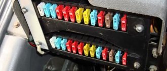
Additional fuse and relay block VAZ 2107 injector located under the glove compartment
Providing electricity
The G7 is responsible for providing consumers with electricity:
- Battery voltage 12 V, capacity 55 Ah;
- generator type G-222 or 37.3701;
- voltage regulator Ya112V, which automatically maintains the voltage within 13.6–14.7 V.
Diagram of the power supply system for the VAZ 21074 injector includes a generator, battery and voltage regulator
Engine starting
The starting system in the VAZ 21074 is a starter and ignition switch powered from the battery. There are two relays in the starter circuit:
- auxiliary, which supplies power to the starter terminals;
- retractor, due to which the starter shaft engages with the flywheel.
The starting system in the VAZ 21074 is a battery-powered starter with a relay and an ignition switch.
Ignition system
In early versions of the seventh VAZ model, a contact ignition system was used, which included:
- ignition coil;
- distributor with contact breaker;
- spark plug;
- high voltage wiring.
The VAZ 21074 contact ignition system consists of a coil, distributor, spark plugs and high-voltage wires
In 1989, the so-called contactless ignition system appeared, the circuit of which included:
- Spark plug.
- Distributor.
- Screen.
- Hall Sensor.
- Electronic switch.
- Ignition coil.
- Mounting block.
- Relay block.
- Key and ignition lock.
In 1989, a contactless ignition system appeared, to the circuit of which a Hall sensor and an electronic switch were added
“Sevens” with injection engines use a more modern ignition circuit. The operation of this circuit is based on the fact that signals from the sensors are sent to the ECU (electronic control unit), which, based on the received data, generates electrical impulses and transmits them to a special module. After this, the voltage increases to the required value and is supplied to the spark plugs through high-voltage cables.
In injection "sevens" the operation of the ignition system is controlled by the electronic control unit of the ECU
Outdoor Lighting
The external lighting system includes:
- Block headlights with dimensions.
- Illumination of the engine compartment.
- Mounting block.
- Glove compartment lighting.
- Instrument lighting switch.
- Rear lights with dimensions.
- Illuminated numbers.
- Exterior lamp switch.
- External lighting indicator lamp (in the speedometer).
- Ignition.
The VAZ 21074 external lighting connection diagram will help in troubleshooting headlights and tail lights
Auxiliary equipment
Auxiliary or additional electrical equipment of the VAZ 21074 includes:
- electric motors: windshield washer;
- windshield wiper;
- heater fan;
- radiator cooling fan;
The connection diagram for windshield wipers uses:
- Gearmotors.
- ED headlight washer.
- Mounting block.
- Egnition lock.
- Washer switch.
Windshield wiper motors drive a trapezoid that moves the wipers across the windshield
Main types of DAAZ carburetors
Of course, carburetor feed mixture supply systems are considered obsolete today. However, according to a number of criteria they are superior to injection designs. A small number of electronic components increases the reliability of the unit and ensures ease of repair work. In addition, carburetor engines do not have high requirements for fuel quality.
Carburetors can be of three types.
- Bubbler. These devices are no longer used. The principle of operation of the unit was to prepare and supply a mixture of air with the vapor fraction of the fuel.
- Membrane-needle-shaped. The assembly consists of several compartments that separate the membranes. They are connected to each other by a rod ending in a needle. This device locks the valve seat through which the fuel mixture is supplied.
- Float This type is most widely used due to its reliability, good quality of the fuel-air mixture and ease of setup. Structurally, it consists of a float-type chamber necessary for the influx of fuel and a compartment where it is mixed with oxygen.

