ABS, or a car's anti-lock braking system, is used to prevent the wheels from locking during emergency braking. It includes an electronic control unit, a hydraulic unit and rotation sensors for the rear and front wheels. The main task of the system is to maintain vehicle controllability, ensure stability and reduce braking distance. Therefore, it is very important to maintain the good condition of all its elements. You can check the ABS sensor yourself; to do this, you need to know what type of sensor is installed on the car, signs indicating its breakdown and methods of checking. Let's look at everything in order.
Sensor types
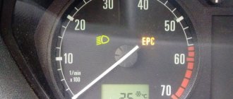
There are two types of sensors on cars:
- passive sensor built on the basis of a coil;
- active sensor that uses the Hall effect.
The passive sensor turns on after the start of movement and reads data from the toothed pulse ring. The passage of a tooth past the device causes the generation of a current pulse, which is read by the control unit. The sensors start working at speeds above 5 km/h and do not respond to contamination.
The active sensor consists of electronic components and a permanent magnet, which is mounted on the hub. When the magnet rotates in the device, a potential difference arises, which is formed into a microcircuit control signal. The information is then sent to the block. Sensors of this design are rare and cannot be repaired.
Inductive passive sensor design
In many cars (both domestic and imported), a passive induction sensor is used as an ABS sensor, which is a coil wound on a magnetic core. It is installed opposite a toothed disk mounted on the hub axis. When the vehicle moves, an alternating voltage appears at the sensor terminals, the frequency of which depends on the speed of rotation of the wheel.
On a note! We have already written about how to check the active Hall sensor, which is used in some car models as an ABS sensor.
Anti-lock braking system (ABS). Description
A car's Anti-lock Braking System is a system that regulates the brake fluid pressure in the brake circuits, which helps prevent the wheels from locking during braking. In other words, this system prevents skidding, which provides the following benefits:
- Increasing vehicle stability.
- Reducing braking distance.
- Saving rubber and preserving the studs on car tires.
In addition to its primary function, anti-lock braking system sensors and valves are used for many other vehicle systems. For example, exchange rate stability system or emergency braking assistance system. The stability control system brakes certain wheels during sharp turns or drifts, which significantly improves safety performance. Brake Assist keeps the brake pedal depressed until the vehicle comes to a complete stop.
Varieties of design
To calculate the angular speed of wheel rotation, 2 types of ABS sensor devices can be used:
- based on an inductive element. They are also called passive, since the sensitive element does not require external power, and the operating principle itself is based on the effect of electromagnetic induction. Despite the simplicity of design and reliability, such devices are becoming less and less common on modern cars. The main drawback of the design is that at low vehicle speeds it is impossible to adequately calculate the wheel speed;
- sensors based on the Hall effect. They are also called active, since the sensitive element needs power - a reference voltage. The signal produced by such speed sensors allows the ECU to more accurately calculate the wheel speed.
And yet ABS is not a panacea
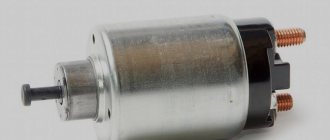
Mono Jetronic central injection system
Experts believe that the presence of ABS in a car creates an illusion of safety for the driver, as a result of which he does not take into account that ABS does not create grip on the road - this is the prerogative of the tread and the size of the contact patch of the tires. Yes, ABS will prevent the brakes from locking up and allow you to maintain control over directional stability and steering, but it does not guarantee a shorter braking distance. When it comes to dry and non-slip roads, it happens just the opposite - the braking distance turns out to be longer than that of a regular car, but the understanding of this, unfortunately, comes too late.
Another question is whether ABS can always reliably recognize the situation? I remember that World Off Road journalists, while testing SUVs, simulated a bad approach to a hill: losing traction halfway up the hill, pressing the brake pedal hard to keep the car on the slope, engaging reverse gear - and gently descending the mountain using engine braking. Everything went fine until it was the turn of the Ford Explorer, and then the Mitsubishi Pajero, equipped with ABS. The jeeps stubbornly rolled down the hill, despite the fact that the testers pressed the brake pedal all the way: the system perceived a slight downward slide on a loose slope and a sharp press on the brake at this moment as a command to unlock the wheels. As a result, both Ford and Mitsubishi could not stay on the slope without using the handbrake. It’s not hard to imagine what a similar situation might entail in real life, if the slope is long enough, a collision occurs closer to the top, the driver is confused (or the parking brake is not working), and some car has already pulled up behind him. In a word, no matter how good ABS is in terms of improving the active safety of a car, the main thing is still the driver, who is obliged to critically think about the road situation and the real capabilities of his “iron friend”.
How the anti-lock braking system works
How to diagnose ABS yourself? — to answer this question with confidence, it is important to know the structure of the system itself. To do this, let’s look at several individual parts of it:
- Speed sensors. Sensors are located near each wheel of the car. They transmit information about the rotation speed of each wheel to the ABS control unit.
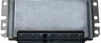
- ABS control unit. The control unit receives signals from speed sensors, analyzes the situation, and, in the event of a wheel lock, transmits a command to the hydraulic control unit.
- The hydraulic control unit, having received a signal about a blocked wheel, closes the brake fluid channel going to this wheel.
The result is that as soon as the wheel is locked, the system “releases” it. Once this happens, it is blocked again. All this happens with high frequency, and as a result, the wheels rotate at maximum effort, but without switching to skidding.
We repair the control unit
If the sensors are in order, the condition of the wiring from them to the electronic unit is not satisfactory, then you need to inspect the control unit.
Do-it-yourself repair of ABS control units is only advisable for those who are very well versed in electronics, know how to use a soldering iron, and have skills in repairing electronic devices. The ABS control unit, as a rule, is non-separable and hermetically sealed with glue. The printed circuit board on it is filled with a special sealant. If you carefully open it, you can look at the wires soldered to the printed circuit board of the unit. Very often they cannot withstand vibration and come off. The broken wire must be carefully unsoldered and another one soldered in its place. For soldering, you need to use an electric soldering iron with a power of no more than 40 W. Rosin or its solution in ethyl alcohol is used as a flux.
To check the hydraulic valve coils, you need to free their terminals from the sealant and apply a voltage of 12 V to them. A normal coil should work like an electromagnet, attracting steel objects to itself.
Some time after the repair, the printed conductors on the control unit board will be completely corroded. For the most part, the control unit needs to be replaced.
Common breakdowns
A slight cracking sound when pressing on the brake pedal is quite normal. This sound occurs due to the functioning of modulators. If the ABS is faulty, its indicator lights up and does not go out even when the engine is running. There are several most common malfunctions of the anti-lock braking system:
- Deactivation based on self-diagnosis results. This may be caused by a malfunction of the control unit or damage to the ABS touch sensor wiring.
- After activation, ABS self-diagnoses, but then turns off. This problem can be caused by broken wires, broken contacts or their oxidation, where the supply of power and signals is disrupted.
- An error appears, but the ABC sensor works. This is a consequence of a break in the touch sensor. It can also be caused by differences in tire pressure or even different tread patterns.
- Complete loss of system functionality. There can be a lot of reasons for this, ranging from sensor breakdowns to wear of the wheel bearings.
To identify a malfunction, you need to check the pressure and play in the tires, the performance of the comb and rotor. If the elements have chips, then it is better to completely replace them. If the problem remains unresolved, then the reason most likely lies in the electronic component. In this case, you need to get a diagnostic code.
Main types
The ABS sensor is read as the primary measuring part of the anti-lock braking system.
The device consists of:
- A meter placed permanently near the wheel;
- An induction ring (rotation indicator, impulse rotor) installed on a wheel (hub, wheel bearing, CV joint).
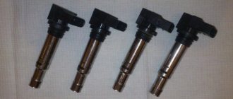
The sensors are available in two versions:
- Straight (end) cylindrical shape (rod) with a pulse element at one end and a connector at the other;
- Angled with a connector on the side and a metal or plastic bracket with a hole for a mounting bolt.
Two types of sensors are available:
- Passive - inductive;
- Active - magnetoresistive and based on a Hall element.
ABS allows you to maintain controllability and significantly increase stability during emergency braking
Passive
They are distinguished by a simple operating system, but are quite reliable and have a long validity period. Does not require a power connection. An inductive sensor is essentially an induction coil made of copper wire, in the middle of which there is a stationary magnet with a metal core.
The meter is located with the core to the pulse rotor in the form of a wheel with teeth. There is a certain gap between them. The rotor teeth are rectangular in shape. The opening between them is equal to or slightly larger than the width of the tooth.
While the vehicle is in motion as the rotor teeth pass near the core, the magnetic field penetrating the coil is constantly changing, forming an alternating current in the coil. The frequency and amplitude of the current are directly dependent on the speed of the wheel. Based on processing of this data, the control unit issues a command to the magnetic valves.
The disadvantages of passive sensors are:
- Relatively large dimensions;
- Poor accuracy of readings;
- They begin to function when the car picks up speed over 5 km/h;
- Triggered by minimal wheel rotation.
Due to frequent errors, they are installed extremely rarely on modern cars.
Magnetoresistive
The work is based on the property of ferromagnetic materials to change electrical resistance when exposed to a constant magnetic field.
The part of the sensor that controls changes is made of two or four layers of iron-nickel plates with conductors applied to them. Part of the element is installed in an integrated circuit that reads changes in resistance and generates a control signal.
The impulse rotor, which is a magnetized plastic ring in places, is rigidly fixed to the wheel hub. During operation, the magnetized sections of the rotor change the environment in the plates of the sensitive element, which is recorded by the circuit. Its output produces pulsed digital signals that enter the control unit.
This type of device controls the speed, direction of rotation of the wheels and the moment they come to a complete stop.
Magnetoresistive sensors record changes in the rotation of vehicle wheels with great accuracy, increasing the efficiency of safety systems.
Based on Hall element
This type of ABS sensor operates based on the Hall effect. In a flat conductor placed in a magnetic field, a transverse potential difference is formed.
Hall effect - the appearance of a transverse potential difference when a conductor with direct current is placed in a magnetic field
This conductor is a square-shaped metal plate placed in a microcircuit that includes a Hall integrated circuit and a control electronic system. The sensor is located on the opposite side of the pulse rotor and has the form of a metal wheel with teeth or a plastic ring, magnetized in places, rigidly fixed to the wheel hub.
The Hall circuit continuously produces signal bursts of a certain frequency. At rest, the signal frequency is reduced to a minimum or dies out completely. During movement, magnetized areas or rotor teeth passing by the sensing element cause changes in the current in the sensor, which are recorded by the tracking circuit. Based on the received data, an output signal is generated and sent to the control unit.
Sensors of this type measure speed from the beginning of the vehicle’s movement and are distinguished by the accuracy of measurements and the reliability of their functions.
Self-diagnosis of ABS
Important: The brake controller de-energizes the valve relay when a diagnostic trouble code is detected. The scan tool in Data List mode displays that the valve relay is de-energized. This condition is not a malfunction.
Important: For safety reasons, it is recommended not to drive the vehicle with diagnostic equipment connected. An exception is a trip to check the speed of rotation of the wheels, provided that the requirements for the test are met.
The brake system controller has a self-diagnostic function and can independently detect, and in many cases isolate, system faults. If a malfunction is detected, the brake system controller enters a code corresponding to this malfunction, turns on the ABS warning lamp and/or the EBD warning lamp, and, if necessary, turns off the ABS and/or EBD for the duration of the current ignition cycle. At each ignition cycle, the brake controller performs a self-test if the vehicle speed is > 6 km/h and the brake pedal is not depressed, or if the vehicle speed is > 15 km/h and the brake pedal is depressed. During self-diagnosis, the operation of all solenoid valves, electric pump and relays is checked by turning them on/off. If a malfunction is detected, the corresponding diagnostic code will be entered into the controller's memory.
DIY ABS diagnostics
The very first sign of a malfunctioning ABS system is a light on the dashboard. After it lights up, it is important to immediately make a diagnosis. Let's consider the actions that need to be taken if the ABS malfunctions:
- Check the fuses and relays of the anti-lock braking system control unit.
- Compare the tire pressure - it should be the same everywhere.
- Examine the rotor of each sensor for contamination.
- Use a tester to measure the resistance in each of the sensors with the ignition on. Lift the wheel on a jack and rotate it and observe the changes.
- Check the integrity of the wires coming from the sensors to the control unit.
- Check the integrity of the wires going to the ABS hydraulic unit.
The best diagnostic option would be to check by connecting a laptop or smartphone to the diagnostic connector - this will save a lot of time and instantly determine the cause of the breakdown.
Analysis of diagnostic results
The problem with the ABS function does not always lie in the sensors. The culprits of system failure may also be the wires connecting the elements to the control unit. That is why it is necessary to carry out 3 measurements and draw the following conclusions based on the results:
- If the resistance of the ABS sensor tends to zero or, conversely, the device shows an infinity symbol, then there is a malfunction of the element itself. Another option is a violation of the insulation or a break in the section of conductors from the connector to the sensor.
- The tester shows that the resistance is within normal limits, but when the brake disc rotates, its value remains constant. There are two versions here: severe contamination of the gear ring (as an option - destruction) and, again, failure of the sensor.
- The absence of voltage in the supply line indicates a break in the electrical circuit coming from the controller.
In the first case, it is necessary to remove the device from the hub and inspect the wires for fractures, breaks or short circuits. To be sure, measure the resistance again, while moving the conductors. If the result is negative, buy and install a new part.
If the resistance remains the same, get to the gear ring, clean it thoroughly and inspect it. If you find mechanical damage, it is better to replace the spare part.
Advice. Sometimes unscrupulous or ignorant auto mechanics damage the ring when repairing the suspension, or even throw it away completely. When picking up your car from a mechanic, always check that this important part is present.
In the case when there is no voltage in the controller circuit, you should ring this section of the wiring. How to do it:
- Find out where the electronic control unit for the hydraulic valves is located. For example, in a Chevrolet Aveo it is located behind the brake fluid reservoir, and in a Renault Megane it is located on the side of the alternator drive belt.
- Remove the block from the ECU and clean the contacts. Find the pinout of the wires or track them by color.
- Place a shorting jumper on the block located near the wheel. Test the circuit with an ohmmeter or a regular light bulb with a battery.
The easiest way to find the ECU if there is no documentation for the car is to follow the brake pipes leading to the hydraulic unit. The latter stands next to the controller or is connected to it by a bundle of wires.
If an open circuit is detected, you will have to look for the defect along the entire line in order to eliminate it. The work is quite complex, so it should be entrusted to an experienced auto electrician.
Clearing Diagnostic Codes
Necessary equipment
Scan ToolDiagnostic codes can be cleared from the brake controller memory as follows:
- Select the "Clear DTCs" command on the scan tool.
Detailed instructions are provided below. Once clearing is complete, verify that the system is functioning normally and that there are no codes present. The controller will not allow codes to be cleared until all codes have been reviewed. Diagnostic codes cannot be cleared by turning off the controller, power to the battery, or turning the ignition switch to the LOCK position.
Symptoms of a problem
There is a yellow or orange indicator light to check the operation of the system. In normal condition, when the ignition is turned on, the warning light on the instrument panel lights up, then self-diagnosis of the system elements is performed and the icon goes out automatically.
Signs of breakdown of ABS system elements:
- The warning light for the system while driving comes on;
- stable wheel locking during sudden braking;
- absence of sounds indicating ABS operation (brake pedal vibration);
- the appearance in the memory of the electronic system of error codes related to the ABS.
Do not use the vehicle if there are signs of ABS malfunction. Brakes designed to work with the anti-lock braking system will not function properly when disengaged.
Checking the sensor without instruments
The most crude way to check the health of the sensor is to test the magnetic field created during operation of the device. To do this, a steel object is applied to the sensor, which should be attracted when the ignition is turned on.
It is possible to visually inspect the device for cracks in the housing or noticeable breaks and oxidation in the wiring. It is recommended to inspect the plug and the condition of the contacts in it; oxidation is the cause of deterioration in signal conductivity.
Let's sum it up
Taking into account the above information, it becomes clear that a number of possible nuances should be taken into account as part of diagnosing the ABS system. First of all, it is important to understand that even if the scanner indicates a faulty sensor, replacement is the last thing to do.
At the initial stage, you should separately check the wiring, as well as the gaps between the inducing ring and the tip, the condition of the indicated system elements, etc. It is also important to pay attention to the condition of other parts installed next to the ABS sensors.
Finally, we note that the service life of sensors and other structural elements directly depends on the operating conditions. When driving, avoid driving on rough terrain to avoid damaging the wiring to the ABS sensors. It is also undesirable to plunge the wheels into mud or puddles, drive aggressively in sand, etc.
We also recommend reading the article about why the brake pedal has become soft or hard. From this article you will learn why the hardness of the brake pedal changes, as well as what to do in such a situation, how to find and eliminate the cause.
It is also recommended to periodically clean the ABS system parts (with a soft brush or cleaner), and check the gap between the sensor and the comb. Finally, we note that during the repair of the chassis and suspension, it is necessary to separately take into account all the subtleties and nuances discussed above. Only this approach allows you to increase the service life and achieve trouble-free operation of ABS on your car.
How to use a tester to check the ABS sensor for functionality
Its performance can be checked using a multimeter. To do this, you need to move the multimeter to the “diode” position. Why? Most ABS sensors in the circuit have protection in the form of a diode connected in series with the circuit. That is, a regular call can lead to incorrect information.
It must be “ringed” in both directions. Typically, the resistance of the ABS sensor ranges from several hundred ohms to 2 kiloohms.
However, testing the sensor directly from its connector does not provide complete information about the passage of its signal to the ABS unit.
In many cases, the cable connecting the sensor connector to the ABS unit is damaged. Such malfunctions are especially common for rear wheel ABS sensors, since the cable length can be more than 3 meters, and manufacturers do not always design its routing correctly.
During the repair of ABS systems, there are cases of up to three fractures or rubbing of the anti-lock braking system sensor cables.
In order to check the sensor from the ABS control unit, you need to find the pinout (connection) of the connector in reference books or on the Internet. Next, you should disconnect the connector from the block and ring the ABS sensors directly from the connector contacts.
We remind you once again that the type of ABS connector and sensor contacts will be different for each car model; reference data should be used. ABS blocks (they can be easily found under the hood by the large number of brake pipes that go with them) are usually marked with their classification, for example BOSCH 5.2.
If, as a result of checking with a multimeter, the ABS sensor rings in one or both directions, this is not evidence of its serviceability.
Structurally, it is made in the form of an inductance coil placed in a magnetic core. The coil has a large number (up to several thousand) turns of very thin insulated wire.
Often moisture gets inside the sensor, and this is very likely, since it is located in the most corrosion-prone area in the immediate vicinity of the wheels. Water, especially saline solution, can cause interturn short circuits. In this case, the winding resistance will change slightly, but the quality factor drops tens of times. This leads to a decrease in the signal level of the ABS sensor and its inoperability.
Very often during operation, especially after replacing hub and wheel elements, the ABS fault light starts to light up. Computer diagnostics show a lack of signal from the ABS sensor, for example, the right front wheel.
The owner replaces it based on diagnostic readings, but the ABS system remains faulty. Sometimes, after removing the error with the scanner, the malfunction light goes out, but as soon as you drive a few hundred meters, make a couple of brakes, it lights up again.
The issue here is not the sensor, but the design features of the signal formation (induction) of the wheel rotation sensor.
How to check the ABS sensor with a tester
So, your ABS light comes on on the instrument panel , what should you do? First of all, it is important to understand that this type of sensor is checked according to two parameters:
- Resistance;
- Voltage.
At specialized stations, the ABS sensor is checked by connecting an oscilloscope . In this case, the wheels are turned manually, and a sine wave is visible on the device screen. It shows the dependence of the signal frequency on the power of oscillatory pulses. Sometimes some craftsmen take measurements using the Ts-20 .
On it, the inspector can see deviations of the needle, and if the device is digital, then an increase in the voltage value. Diagram of the ABS sensor signal on an oscilloscope
At home, to test the ABS sensor, you can make a special device, which will consist of a resistor from 900 Ohm to 1.2 kOhm , as well as a pair of wires. At the ends of the wires you need to place clamps that can be connected to the contact group of the sensor itself.
After this, you need to check each wheel. Turn the wheels one way and then the other. At the same time, connect our resistance to the sensors, turn on the ignition and observe the behavior of the instrument panel warning light. In cases where the light goes out when the resistance is connected, the sensor can be considered faulty. Agree, this method is very interesting, but labor-intensive, so let’s move on.
To check the ABS sensor with a tester , you will need any modern multimeter. First of all, we measure the resistance, which can be different for each car and its sensor. That is why you first need to find the standard resistance readings for your car. The bulk of ABS sensors fit into the range from 1.2 to 1.8 kOhm . When the tester is connected to the sensor and is measuring resistance, try shaking the wires going to the sensor itself. In this case, the instrument readings should not deviate, and if this happens, then there is an open circuit.
Checking the ABS sensor
After these measurements, disconnect the contacts of the multitester and switch it to voltage measurement mode . Now you need to spin the car wheel to about 40-50 rpm . Next, we monitor the readings of the sensor that will produce voltage. On all sensors it is equal to 2 volts.
Of course, under ideal conditions, you need to check the sensor by connecting special software, which can indicate more accurate parameters of the ABS operation and its malfunctions.
Multimeter test method
If you know how to use a multimeter, then you can check the passive ABS sensor using even the cheapest universal meter. Correspondence of possible faults and methods for their diagnosis:
- open circuit of the coil winding. Set the multimeter to diode testing mode. If the device shows infinite resistance, then there is an open circuit in the circuit;
- unsoldering the coil winding contacts. The nature of the failure is the same as in the case of a break;
- short circuit. To check, switch the multimeter to resistance measurement mode - ohmmeter, measurement range - up to 20 kOhm. Pre-measure the resistance of a previously working sensor or find out the standard value from the technical documentation. Typically, the resistance of serviceable elements ranges from 0.7 to 2.5 kOhm. It is important to take into account that the resistance of working sensors on the front and rear axles can differ significantly.
If the ABS sensor is removed from the car, then you can simulate the rotation of the master disk with any magnetic metal object.
Due to the aggressiveness of the installation environment, ABS sensors on motorcycles may have an electromagnet instead of a permanent magnet, which must be taken into account when checking without dismantling (the ignition must be on).
How to make your search easier
In order not to carry out testing with a tester on each wheel separately, remove the connector of the ABS control unit. The video shows that once you understand the pinout, you can quickly find which circuit has a short circuit or an open circuit.
What to do first?
It is necessary to check the ABS sensors located near each wheel hub. Your task is to detect a violation in the connection of the sensors, a broken wire or damage to the ABS sensor housing. In any of these cases, you will one way or another see the corresponding indicator on the panel, well, provided that the system control unit itself is working and not “buggy”.
Checking the ABS sensor - measuring the resistance
- We jack up the wheel on which you think the inoperative or faulty sensor is located, or each wheel in turn if you don’t know exactly which sensor is faulty.
- Next, remove the wheel and gain access to the sensor.
- Remove the housing, as well as the protective control unit and connectors that supply power to the sensors.
- After that, we insert wires into the circuit of wires with PIN connectors and connect them with the sensor and multimeter.
- We measure the resistance and compare it with the one that should be by default (you can find it in the manual) or with a representative of the manufacturer of your car.
- We check the wiring for breaks or short circuits.
- Rotate the wheel while watching the multimeter readings, the resistance should change.
- Device – leg – 5-26 Ohm.
- Device – “ground” – from 20 kOhm or more.
For more details on how to check the ABS sensor, watch this video:
Checking the ABS sensor using a tester - measuring the voltage
- Let's jack up the wheel.
- Turn on the multimeter, set the DC voltage measurement mode.
- We connect the electrodes of the device to the connectors and check the readings, while rotating the wheel (about 1 rpm).
- A working ABS sensor will show voltage on the device
0.25-1.2 Volts. If the wheel rotation speed is higher, the readings will increase accordingly.
How to check a sensor with an oscilloscope?
To diagnose the serviceability or malfunction of the ABS sensor, you can even use an oscilloscope or, more simply, a tester. When connected, a graph will be displayed on the device; using amplitude analysis, you can judge the serviceability or malfunction of the sensor.
The problem is that this device is not available at every service station, not to mention the garage in which you are going to conduct all your “experiments”. The device is expensive and quite difficult to understand, so to work with it you need to have certain knowledge and skills.
In modern cars, the ABS system has a self-diagnosis function; using special software, you can read the error code and then decipher it using a special table.
ABS Diagnostic Circuit Check
| Step | Operation | Values | Yes | No |
| 1 |
Is the scan tool reading data from the brake controller? | — | Go to Step 2 | Go to Step 6 |
| 2 | Check the meter readings. Are any current fault codes displayed? | — | See corresponding code table | Go to Step 3 |
| 3 |
Does the warning light come on for 4 seconds and then go off? | — | Go to Step 5 | Go to Step 4 |
| 4 | Check the condition of the ABS warning light. Does the ABS warning light stay on and stay on? | — | See “ABS warning light stays on” | See “ABS warning lamp faulty“ |
| 5 |
Does the warning light come on for 4 seconds and then go off? | — | Go to Step 12 | See "EBD warning lamp faulty" |
| 6 |
Is the voltage on all pins within the specified range? | 11-14 V | Go to Step 7 | See "Controller Power, No Diagnostic Codes" |
| 7 |
Does the measured resistance match that shown in the table? | ≈ 0 Ohm | Go to Step 9 | Go to Step 8 |
| 8 | Repair the open in the BLK and BLK/WH wires that failed the test. Is the repair complete? | — | The system is working properly | — |
| 9 | Using a digital voltmeter, measure the resistance between pin 11 of the brake controller connector and pin 12 of the diagnostic connector. Is the measured resistance less than that shown in the table? | 2 ohm | Go to Step 10 | Go to Step 11 |
| 10 | Replace the ABS unit. Is the repair complete? | — | The system is working properly | — |
| 11 | Repair open or high resistance in the BLS circuit between pin 11 of the brake controller connector and pin 12 of the diagnostic block. Is the repair complete? | — | Go to Step 1 | — |
| 12 | Test the vehicle while driving on the road as described above. Are any fault codes stored? | — | See corresponding code table | — |
How to fix problems
After checking the tools and identifying a faulty drive, you can begin repairs. Some owners repair sensors by replacing the wiring or rewinding the coil.
Sensor failure
A faulty passive type sensor can be repaired yourself:
- Remove the sensor from the hub. The fastening bolt often becomes sour, so you need to unscrew it carefully. For removal, it is allowed to use a liquid like WD40.
- Remove the protective coil housing. Removal is done with a file. The cut must be made very carefully so as not to damage the housing and winding.
- Remove the protective film from the packaging by prying it off with a sharp knife.
- Carefully unwind the thread from the bobbin. During the removal process, the version of thread breakage is confirmed. What remains is an empty wire-coil ferrite core.
- Wrap new film. As a core, you can use the copper wire of the common relay coils of the RES-8 type. Winding can be done with a drill with smooth speed control. Be careful because a broken thread will take you back to where you started. It is recommended to wind the wire to the top level of the coil.
- Check resistance. Most coils are in the 0.9-1.2k ohm range. For clarification, it is recommended to measure the parameter on a known-good sensor located on the opposite side of the axis. The resistance is adjusted by unwinding the excess wire. If the reading is low, you will need to use a different stream or rewind. Secure the thread from the self-tapping tape with masking tape or other tape.
- Welding wires at the coil terminals, which serve as a connecting link between the winding and the harness. For terminals, it is recommended to use insulated braided wire, which has a higher resistance.
- Install the coil into the old housing. If during disassembly of the device it received significant damage, the coil is filled with epoxy resin. To do this, the part is placed in a metal cup of a suitable size, for example, a capacitor housing. The air gap between the coil and the glass is carefully filled with resin. When pouring, it is recommended to avoid large air gaps. After the resin has completely hardened, the body is removed.
- Replace the sensor bracket with epoxy resin. Inspect the product for cracks and voids in the insulation. Detected defects are filled with resin.
- Return the repaired sensor to its place and check the operation of the ABS system. When installing the device, it may be necessary to modify the resulting body, which is done with a file and sandpaper. The sensor installed in the field must have a gap between the coil and the toothed ring within the range of 0.9-1.1 mm. When space is reduced, it is recommended to bring it up to standard by installing spacers.
You need to drive the car for some time, checking the brakes at different speeds. There are times when the ABS spontaneously activates at certain wheel speeds, usually just before stopping. Then you will need to look for the gap, correcting it with gaskets or trimming the sensor body.
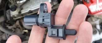
Another repair option is to install a modified crankshaft position sensor from domestic cars:
- We remove the “original” sensor and modify the body of the “donor” part. Most often, this role is played by the DPKV of the ZMZ-406 engine, which has a resistance within 800 Ohms. When remaking, it is necessary to try to ensure that the core is parallel to the wound coil and the toothed ring mounted on the shaft. The distance between the sensor and the ring should be between 0.2 and 0.3 mm.
- Test the operation of the device. On some Japanese vehicles, the ABS warning light may come on intermittently. The situation can be corrected by changing the connection of the wiring contacts.
Both sensor repair options require the owner’s perseverance and ability to work with various tools. If a car user doubts its capabilities, it is recommended to buy a new device or find the product when dismantling cars.
Wiring problem
If the problem with the loss of functionality of the sensor lies in the wiring, it can be replaced:
- Unscrew the sensor holder from the wheel hub.
- Disconnect the cable plug.
- Remove the sensor along with the cable. In this case, it will be necessary to remove the mounting brackets installed on the wiring.
- Measure the installation distances for the brackets. It is recommended to draw a diagram and photograph the factory position of the supports.
- Cut the sensor from the wire, leaving a margin for welding.
- Check the integrity of the cable remaining on the sensor. If the area is not damaged, you can begin installing a new wiring segment.
- Remove all protective covers and fasteners from the old cable.
- Choose a wire with a suitable outer diameter and cross-section.
- Install previously removed guards and fastenings onto the new harness. To facilitate assembly, it is recommended to use a soap solution.
- Solder the sensor and insert it into place.
- Carefully insulate the joint. The tightness of the connection determines the accuracy of operation and service life of the part being repaired.
- Reinstall the sensor, check the functionality of the ABS system, and make sure there are no errors during operation.
Need for replacement
Any system malfunction will definitely be diagnosed - ABS has built-in diagnostics. It is triggered before each engine start. If the system is working normally, this indicator will light up when the engine starts, and then go out after half a minute.
But if the controller does not work correctly, then when the engine is running, the indicator will be constantly on or will blink while driving. This is one of the first signs that one of the sensors is faulty.
In addition, if the sensor or sensors are faulty, the on-board computer may generate errors; during sharp braking, the wheels may lock, and there may be a characteristic vibration on the pedal when braking. When the handbrake is off, the parking brake light may come on.
If your car has at least one of the problems described, then you need to carry out a competent and complete diagnosis. If it is discovered that the sensor has failed, then it needs to be replaced with a new one.
However, before replacing the front ABS sensor, you can try checking the gaps between the sensor and the ring and the tire pressure. You can diagnose and visually check the entire electrical circuit. If no obvious faults are found, then the problem is in the sensors or electronic systems.
Alternative verification method
When you don't have a multimeter at hand, you can check the ABS sensor in a simpler way. It will work when only one element fails, and not several. Diagnostics is performed as follows:
- Disconnect the connector on one wheel sensor. Next, you need to start the engine and drive a few meters.
- If the second light on the brake system (or handbrake) malfunctions comes on, then the element being tested is operational. Connect the block and repeat the operation on the next wheel.
- If one sensor is broken, the ABS indicator lights up, and if there are two or more sensors, the handbrake lamp lights up. When the second indicator on the panel does not light up, it means that you have disconnected the faulty element.
The method allows you to determine the location of the problem, but not its nature. For a more accurate diagnosis, you need to use a tester with an ohmmeter.
The presence of ABS in a vehicle greatly increases traffic safety. Gradually, car parts wear out and may become unusable. Knowing how to check the ABS sensor, the driver can identify and fix the fault in a timely manner without resorting to the services of a workshop specialist.
ABS sensor repair
If a faulty ABS sensor is detected, it is dismantled, after which the issue of replacement or repair is decided. The cost of the device is quite high, and often there is a long wait for its delivery, which makes repairs quite feasible. The work is performed in the following order:
1. The sensor is disassembled by cutting off the part in which the measuring coil is located with a hacksaw. The body is carefully filed in a circle so as not to damage the fasteners.
2. The plastic casing protecting the coil is removed using a sharp knife and the winding is unwinded from the frame.
3. Wind a new coil with a wire of the same diameter. The RES-8 relay winding is suitable for this. The number of windings must provide the required resistance value - 0.92-1.22 kOhm. The work is carried out very carefully, since the wire is quite thin, and if it breaks, the process begins again.
4. The ends of the wires are soldered to the terminals, and the coil is effectively insulated from moisture using silicone or wax sealant.
5. The sensor is assembled by restoring the old housing. If the shell is critically damaged, it is made independently from the body of an electrolytic capacitor, suitable in size, and epoxy glue. A hole is made at the bottom of the body for the coil rod. After placing the updated part there, glue is poured.
6. After the glue has dried, the capacitor shell is removed, and the sensor mount is glued to its original place.
7. After the repair is completed, the sensor body is ground with sandpaper to accurately fit the socket. During the installation process, observe the following rules:
- The core of the device is placed parallel to the teeth of the response disk and is controlled so that it does not overlap a pair of adjacent teeth;
- A gap of 0.9-1.1 mm is left between the tooth and the core.
At the end of the installation, check the functionality of the system by starting the engine and making sure that the ABS indicator goes out 6 seconds after the start.
How to change ABS sensors?
Often on modern cars they are installed on all four wheels. Removal of the front axle elements is carried out from the bottom or, on some models, from under the hood. But when replacing the rear ABS sensor, access is only available from below.
For the work you will need a certain set of tools. These are socket and open-end wrenches, a wheel wrench for removing wheels, a jack, a hammer, screwdrivers, a liquid wrench, and a multimeter.
Replacement instructions
Let's look at the process of replacing a Toyota ABS sensor on the rear axle. The car is placed on a level surface with the hand brake applied. To increase safety, chocks are placed under the wheels. At the same stage, you need to remove the negative terminal from the battery.
Next, the rear seats, threshold trim, and door seal are dismantled. You need to get to the connector. To do this, bend the clamps and pull off the trim near the shock absorber strut mount. Then disconnect the connector.
Next, the car is raised with a jack, and a block is placed under the bottom for safety. After this, you can unscrew and remove the wheel. The sensor is installed on a bracket. To replace the ABS sensor, you need to spray the bracket with liquid key and wait a little. Then unscrew the mounting bolt. By tapping the element, remove the sensor with a screwdriver.
Then you need to unscrew the fasteners holding the wire brackets. Two bolts on the arch, and one on the shock absorber strut. The wire should be pulled out into the interior.
Installation of the new device is carried out in the reverse order. This completes the operation. Sensors on other car models are changed using a similar scheme (replacing the Lancer ABS sensor is no exception).
If replacing the ABS sensor does not produce results
Having considered the available ways to check the ABS, it may seem that it is enough to identify the problematic sensor and replace it. Replacing the wiring may also seem like a solution.
However, in reality it is not so simple. Often, car enthusiasts are faced with the fact that even after replacing the ABS sensor, the system still does not work. By the way, this also happens in cases where the ABS was working normally, but after replacing the hub or wheel bearings the ABS light comes on.
In this case, computer diagnostics show that there is no signal from the ABS sensor. Next, the sensor is replaced, but the ABS system still does not work. Even if you remove the error using a scanner, after a few meters or after 1-2 braking the error lights up again.
So, the reason in this case is not the sensor at all. Often the culprit is the way the signal is generated from the wheel rotation sensor. More precisely, in the case when the inducing element is the comb ring on the hub (ABS ring). The end part of the sensor itself is located near the comb, which is made of soft magnetic material.
The gap between them is minimal, only from 0.2 to 0.8 millimeters. If dirt or stones adhere to this area, this will lead to a violation of the gap, displacement of the sensor, and destruction of the tip. Naturally, the signal will become weak. Also, the comb itself may become clogged, which causes failures.
Given this feature, before installing a new sensor, you must first check the gap and clean the comb with a solvent. When finished, check the gap size with a feeler gauge. It is not allowed to increase the gap by more than 1 mm. It is also important to inspect the elements for possible damage.
If you are not exactly sure, you can compare the parts with the same devices on another wheel. If damage to the wheel comb is detected, the element needs to be replaced.
Let us also add that the inducing element on some cars can be implemented in the form of a rubber ring or magnetic tape. There are magnetic plates inside the ring. It happens that during in-line repairs this ring is simply not installed. Naturally, the ABS system will not work without them.
As for the tape, it is easy to damage. This means that you need to work carefully, since if the belt is damaged, the ABS sensor will not work properly. It is also important to ensure that when replacing the wheel bearing, an element with an inducing ring is installed in the case where exactly such a design is provided on the car.
ABS device
The anti-locking device consists of several components:
- Speed meters (acceleration, deceleration);
- Control magnetic dampers included in the pressure modulator and located in the brake system line;
- Electronic monitoring and control system.
Pulses from the sensors enter the control unit. In the event of an unexpected decrease in speed or a complete stop (blocking) of any wheel, the block sends a command to the desired valve, which reduces the pressure of the fluid that enters the caliper. This weakens the brake pads and allows the wheel to move again. When the speed of the wheel is equalized with the others, the valve closes and the pressure in the entire system is equalized.
General view of the ABS system in a car
On new cars, the anti-lock braking system activates up to 20 times per second.
The ABS of some vehicles includes a pump, the function of which is to quickly increase the pressure in the desired section of the highway to normal.
This is interesting! The effect of the anti-lock braking system is felt by reverse shocks (impacts) on the brake pedal when there is strong pressure on it.
Based on the number of valves and sensors, the device is divided into:
- Single channel. The sensor is located in the differential area on the rear axle. If even one wheel stops, the valve reduces the pressure on the entire line. Found only on older cars.
- Two-channel. Two sensors are located diagonally on the front and rear wheels. One valve is connected to the main line of each bridge. It is not used in cars manufactured according to modern standards.
- Three-channel. Speed meters are located on the front wheels and the rear differential. Each has a separate valve attached to it. Used in budget rear-wheel drive models.
- Four-channel. Each wheel is equipped with a sensor and its rotation speed is controlled by a separate valve. Installed on modern cars.
Questions about selecting and replacing sensors
DSAs are installed on wheels, so during operation they are subject to various negative influences and various breakdowns occur. A malfunction of the DSA is indicated by the corresponding indicator on the dashboard; also, the failure of one or more sensors is manifested by a change in the nature of the brake system operation - unreasonable activation of the ABS or, conversely, lack of response from the ABS during sudden braking, a characteristic crunch during normal vehicle movement, etc. .d. In all these and other situations, the ABS sensor should be replaced.
For replacement, you should choose sensors only of those types and models (or rather, catalog numbers) that were previously installed on the car. In no case is it permissible to replace the type of sensors, for example, installing a device based on a Hall IC instead of an inductive DSA, and vice versa. Different types of sensors generate certain types of signals, and the ECUs designed to work with them have input circuits that are incompatible with other types of sensors. Therefore, installing the wrong DSA will only aggravate the situation.
Removal of the old sensor and installation of a new one must be carried out strictly in accordance with the vehicle repair and maintenance instructions. Typically, to dismantle the DSA it is necessary to unscrew one screw (bolt) and remove the electrical connector. Then you should thoroughly clean the sensor installation site from any dirt, and then install a new device. After installation, the sensor and the entire system, as a rule, do not require calibration or adjustment - everything starts working immediately.
If you make the right choice and correctly replace the DSA, the active safety systems of your car will again reliably perform their functions, helping the driver overcome difficult and dangerous road situations.
Briefly about the principle of operation
The ABS function simulates the harsh, repeated pressure on the brake pedal experienced by drivers of older cars on slippery roads. Electronics uses this method of braking much more efficiently, locking and “releasing” the wheels several times per second. The operating algorithm is as follows:
- During sudden braking, the control unit monitors the behavior of the wheels using sensors.
- If one or more wheels stop rotating, the ECU issues a command to a hydraulic valve that releases fluid from that circuit. The pads stop holding the disc and rotation resumes.
- By comparing the readings of all meters, the controller makes sure that braking is not complete and closes the hydraulic valve, and the wheel is blocked again. The cycle, lasting a fraction of a second, is repeated until the machine stops completely.
Important! If the functionality of one or more sensors is impaired, the ABS will fail entirely, since the electronic unit will not be able to compare the behavior of the wheels.
The latest generation ABS sensor is a coil with a semiconductor element installed in a stationary part of the hub. In the immediate vicinity of it, a toothed ring is attached to the brake disc, whose rotation is monitored by a sensor. It happens like this: the controller supplies voltage to the device, and it constantly changes the resistance due to the passage of a series of teeth on a rotating ring.