The power supply system of a modern diesel internal combustion engine is a whole complex of devices. The main task is not just supplying fuel to the injection nozzles, but also supplying fuel under high pressure. Pressure is necessary for high-precision dosed injection into the combustion chamber of the cylinder. The diesel power system performs the following essential functions:
- dosing a strictly defined amount of fuel, taking into account the load on the engine in a particular mode of operation;
- effective fuel injection in a given period of time with a certain intensity;
- atomization and maximum uniform distribution of fuel throughout the volume of the combustion chamber in the cylinders of a diesel internal combustion engine;
- preliminary filtration of fuel before supplying fuel to power system pumps and injection nozzles;
We also recommend reading the article about the design of the high-pressure fuel pump. From this article you will learn about the operating principles of the injection pump, its role in the fuel supply system of a diesel engine and the operating features of the device.
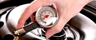
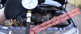
How to independently measure the pressure in the fuel rail of a car and why is it necessary????
Checking the fuel rail pressure is a standard procedure in a long chain of diagnosing engine and fuel system malfunctions.
Often this check is carried out in cases where the engine runs unevenly and there are dips during acceleration. This is one of the mandatory check points if the car jerks during acceleration. I described this in the article “Why does a car jerk during acceleration and acceleration.” Also, this diagnosis is performed in cases where the car has increased fuel consumption.
Requirements for units and components of the power supply system
The following basic requirements apply to all units and components of the power system:
- tightness
- small weight and dimensions
- reliability
- corrosion resistance
- low hydraulic resistance
- simplicity
- low maintenance cost
Fuel lines and fuel supply system units must be located in the engine compartment of the vehicle in such a way that if they malfunction, dripping fuel does not fall on parts that have a temperature that could cause it to ignite.
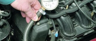
Preparing for measurements
We string a hose onto the inlet fitting of the pressure gauge and secure it with a clamp - we must avoid pressure losses during measurements.
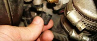
Then you need to remove the cap from the fuel rail. There will be a nipple under it - remove that too. Be careful - if you recently started the car, there will be residual pressure in the fuel system and gasoline may spill out, so have a cloth ready and try to protect your eyes.
When you have removed the plug and nipple, install the second end of the hose that goes to the pressure gauge. We also fix everything with clamps.
Measuring process
Fuel pressure must be measured in 4 operating modes, that is, 4 different measurements will be required.
With the ignition on
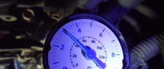
When the ignition is turned on, the fuel pump must supply the system with the fuel needed to start the engine. Therefore, we simply turn on the ignition and look at the readings. The pressure must be above 3 atmospheres.
Idling
Just start the engine and look at the pressure gauge readings. Normal pressure is 2.5-2.7 atmospheres.
When the return line is turned off
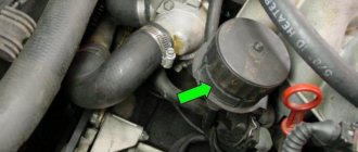
Almost all modern cars have a fuel pressure regulator. It is aimed at preventing excessive pressure from being created in the system. When the limits are reached, it resets the pressure to normal. We clamp the return pipe and get the result on the pressure gauge.
It should be about 7 atmospheres. If you have a 6 atmosphere pressure gauge, the needle should be “filled up”.
Under loads
And one more stage of measurement is the measurement of pressure drops under loads. Just apply the throttle (you can just “tug” the throttle cable if you have a mechanical one) and observe the changes.
During recharging, the pressure should be about 3 atmospheres, and then drop to the idle value - that is, up to 2.5 atmospheres.
Operating principle of RTD
The valve design and operating principle depend on the type of fuel system of a particular vehicle. There are 3 ways to supply gasoline from the tank to the injectors:
- The pump together with the regulator is installed inside the tank; fuel is supplied to the engine through one line.
- Gasoline is supplied through one tube and returned through another. The fuel system check valve is located on the distribution rail.
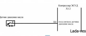
- The circuit without a mechanical regulator provides for electronic control of the fuel pump directly. The system contains a special sensor that registers pressure; the pump performance is regulated by the controller.
In the first case, the return flow is very short, since the valve and electric pump are interlocked into a single unit. The RTD, located immediately after the supercharger, dumps excess gasoline into the tank, and the required pressure is maintained throughout the supply line.
The second option is used in most foreign cars. A valve built into the fuel rail allows excess fuel to flow into the return line leading to the tank. That is, 2 gasoline pipes are laid to the power unit.
There is no point in considering the third circuit - instead of a regulator, there is a sensor whose functionality is checked using a computer connected to the diagnostic connector.
A simple fuel pressure valve installed in the fuel pump unit consists of the following elements:
- cylindrical body with pipes for connecting the supply and return lines;
- a membrane connected to a locking rod;
- valve seat;
- spring.
The amount of pressure in the supply line depends on the elasticity of the spring. While most of the fuel goes into the cylinders (high load on the engine), it keeps the membrane and valve stem closed. When the crankshaft speed and gasoline consumption decrease, the pressure in the network increases, the spring compresses and the membrane opens the valve. The fuel begins to be discharged into the return line, and from there into the gas tank.
The fuel pressure regulator installed in the rail operates on a similar principle, but reacts faster to changes in load and gasoline consumption. This is facilitated by connecting an additional pipe of the element to the intake manifold. The higher the crankshaft speed and the vacuum on the spring side, the stronger the membrane presses the rod and closes the passage of fuel into the return line. When the load decreases and the speed drops, the vacuum decreases and the rod releases - the return flow opens and excess gasoline begins to be discharged into the tank.
Important to remember
When you check the fuel pressure with the ignition on, note that after the ignition is turned off, the pressure in the rail drops to 0.7-1 atmosphere and remains at this level. If it drops to 0, the problem is in the fuel pressure regulator.
Try increasing the number of revolutions to 3000 - if the pressure gauge needle does not stay constant, but falls, this may mean that it is time to change the fuel pump.
If the pressure builds up for a very long time or is lower than required, the fuel filter, fuel pump filter or fuel line may be clogged.
I hope you found it interesting and will take note of this. Subscribe to the channel and give it a thumbs up to see even more interesting articles on automotive topics in your feed every day.
Source
General design of fuel injection pump [edit | edit code]
- Frame.
- Lids.
- All-mode regulator
- Injection advance clutch.
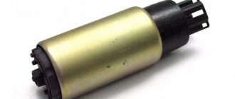
- Booster pump.
- Camshaft.
- Pushers.
- Plungers with drivers or toothed bushings,
- Plunger sleeves.
- Plunger return springs.
- Discharge valves.
- Fittings.
- Rail.
Operating principle of fuel injection pump [edit | edit code]
The cam shaft receives rotation through an injection advance clutch and a gear transmission from the crankshaft. When the cam shaft rotates, the cam runs up against the pusher and displaces it, and it, in turn, compresses the spring and lifts the plunger. When the plunger is raised, it first closes the inlet port and then begins to displace the fuel above it. The fuel is forced out through the discharge valve, which is opened due to pressure, and enters the injector.
At the moment the plunger moves upward, the screw channel located on it coincides with the drain channel in the sleeve. The remaining fuel located above the plunger begins to be drained through the axial, radial and screw channels in the plunger and the drain in the sleeve. When the plunger is lowered, the inlet channel opens due to the spring, and the volume above the plunger is filled with fuel from the booster pump.
Changing the amount of fuel supplied to the injector is carried out by turning the plungers from the rack through an all-mode regulator. When turning the plunger, if the screw channel coincides with the drain channel earlier, then less fuel will be injected. When turning back, the channels will coincide later, and more fuel will be injected.
On some fuel injection pumps (for example, the fuel injection pump of the T-130 tractor), some sections are turned off at idle speed, and accordingly, some of the engine cylinders are also turned off.
Additional fuel injection pump units [ edit | edit code]
Injection advance clutch
— serves to change the injection advance angle depending on the speed. According to the principle of operation, it is a mechanism that uses centrifugal force. Device:
- Drive coupling half.
- Driven coupling half.
- Loads.
- Weight tension springs.
- Weight support pins
The principle of operation of the coupling is as follows. At minimum speeds, the loads are pulled to the center due to the springs and the position between the couplings is the original one, while the injection advance angle is within the adjusted parameter. As the speed increases, the centrifugal force in the weights increases and moves them apart, overcoming the resistance of the springs. In this case, the clutches rotate relative to each other and the injection advance angle increases.
All-mode regulator - serves to change the amount of fuel supplied depending on the engine operating modes: starting the engine, increasing/decreasing speed, increasing/decreasing load, stopping the engine. Device:
- Frame.
- Lids.
- Holder.
- Loads.
- Clutch.
- Levers.
- Backstage bracket.
- Adjustment screws.
- Tension springs.
The operating principle of the regulator is as follows:
- Starting the engine: before starting, the rack is in the position of maximum fuel supply due to the spring, so when starting, the maximum amount of fuel is supplied to the engine. This promotes quick startup. As soon as the engine begins to develop speed, and the centrifugal force in the weights begins to increase, they, overcoming the resistance of the springs, will begin to diverge to the sides and with their internal levers put pressure on the clutch, which will act on the lever, and the lever will pull the rack in the direction of decreasing the fuel supply. The speed will be set in accordance with the spring tension.
- Increasing speed: when you press the gas pedal, a spring is tensioned, which acts on the rack lever and clutch. The coupling and rack are displaced, and the centrifugal force in the loads is overcome. The rack shifts towards increasing the fuel supply, and the speed increases.
- Increasing load - with increasing load and the same position of the gas pedal, the speed decreases, and so does the centrifugal force in the loads. The weights add up and allow the clutch, lever and rack to move in the direction of increasing fuel supply. As the load decreases, the revolutions begin to increase, the centrifugal force in the loads too, the weights begin to diverge and the internal levers move the clutch, lever and rack in the direction of decreasing the fuel supply. At the same time, turnover stops growing.
- Stopping the engine - when the engine stops, the bracket rotates, the bracket link acts on the lever, and the lever acts on the rack. The rack moves so much in the direction of decreasing feed that the feed stops and the engine stops
Learning Common Rail: all the way
The first production cars with this system, developed by , appeared in 1996. It gets its name from a single ramp from where fuel is supplied to the injectors. The main advantage of the system is a sufficiently high fuel pressure in all engine operating modes, which contributes to better mixture formation in the combustion zone and complete combustion. While maintaining the moderate appetite of its predecessors, the CR diesel better meets environmental standards, and such a car is often more dynamic than a gasoline car and is almost as quiet.
The heart of the system is the high-pressure fuel pump, a compact device with one, two or three plungers and a mechanical drive. The injection pump housing is made of aluminum alloy, the plunger sleeves are steel. To prevent the pump from wasting fuel at idle and at low loads, on some three-piston pumps one section is automatically turned off, while double-piston pumps are regulated by dosing devices. To the fuel injection pump itself, fuel is supplied from the tank under a pressure of 6-7 bar by a booster pump. He's either gear
chatted and built into the fuel injection pump housing, or electric - in the fuel intake module or in the line.
Pre-fuel priming pump
Before starting the engine, the system is filled with fuel and supplied to the injection pump using a pre-start fuel priming pump 70. Previously, manually driven plunger and diaphragm (diaphragm) type pumps were widely used. However, nowadays, centrifugal vane pumps driven by an electric motor powered by electrical energy from a battery are increasingly being used. They provide faster fuel pumping, do not require the driver’s muscular energy, and can be used as emergency ones in case of failure of the main fuel priming pump.
Injector repair kit.
Already in the mode of cranking the crankshaft with the starter, the injection pump creates a starting pressure of 350-400 bar. At minimum idle speed - up to 500-600 bar, and at maximum load - up to 1300-1500 bar. There are pumps with pressure up to 2000 bar. Its value is set by a regulator located on the fuel injection pump housing or on the ramp and subordinate to the electronic engine control unit. When issuing commands, the ECU relies on signals from the rail pressure sensor.
Fuel is supplied through high-pressure pipes to the injectors, which open under the influence of an electrical signal. There are two design options - electromagnetic or with a piezoelectric element. The first one was not particularly fast at first, which forced the designers to look for an alternative. In a piezo injector, voltage is applied to a piezo crystal, which instantly expands. The spool compresses the spring, the injector needle opens the way for fuel - and it is injected into the combustion chamber. However, designers continue to improve electromagnetic devices - both options work successfully on modern engines.
About the design features of diesel engines in comparison with gasoline engines
Both diesel and gasoline engines are internal combustion engines. In a global sense, in its design, a diesel engine is no different from a gasoline engine: both have cylinders, pistons and connecting rods. However, in diesel engines the compression ratio is much higher (19-24 units, while in gasoline engines it is 9-11). Therefore, all parts and valves are significantly reinforced (to withstand much higher loads). Therefore, the weight and dimensions of a diesel engine are much more impressive than a gasoline engine.
The main difference lies in the methods of forming the fuel/air mixture, its ignition and combustion. In gasoline engines, a mixture of fuel and air is formed in the intake system, and it is ignited by a spark from the spark plug. In diesel engines, fuel and air are supplied to the working cavities of the cylinders separately. First the air. It heats up to seven to eight hundred degrees and contracts. When fuel is then injected into the combustion chamber under high pressure, it spontaneously ignites, almost instantly.
Thus, no spark is required. And the glow plugs, which are installed in the cylindrical head, are heating elements, like a soldering iron, and they are designed to quickly heat the air in the combustion chamber while the engine has not yet warmed up. This is called a pre-heating system.
When the ignition is turned on, the glow plugs heat up to 800-900 degrees in a few moments, warming up the air and ensuring the process of self-ignition. A warning lamp provides the driver with signals about the operation of this system. The power supply is removed from the spark plugs automatically, 15-20 seconds after starting a cold engine, when its stable and stable operation is already fully ensured. The decisive role in ensuring such engine performance indicators belongs to its fuel system, the design of which will be discussed.
WE DIAGNOSE
There is a minimum of equipment without which it is unreasonable to start working. Diagnostics of electronic systems begins with reading fault codes, checking sensors and actuators. There are no special diesel scanners, there are universal ones, that is, for a wide range of cars, or dealer ones - for a specific brand. To study the signal from the device under test, you need an oscilloscope. But it is expensive; it is more profitable to buy a scanner with an additional oscilloscope function.
Fuel pressure is checked with pressure gauges. Low - mechanical, with a scale of up to 10 bar, and high - with a special device with adapters and a range of at least 2000 bar. And to measure the amount of fuel drained from the injectors, you need your own set.
The troubleshooting algorithm depends on the nature of the failure. If the engine does not start (electronic locks and forgotten secrets do not count), we check the integrity of the timing drive. If the starter rotates the crankshaft with force, this is not bad for the owner, but if without resistance, the repairmen will be happy: the work ahead will be expensive. After all, diesel engines are “plug-in” - when the timing drive is destroyed, the pistons bend the valves, and then whatever happens.
Symptoms of malfunction
The main driver symptom of P0087 is the MIL (Malfunction Indicator Light) illumination. It is also called Check engine or simply “check light”.
They can also appear as:
- The Check Engine Light comes on and there may be more than one code present, such as a lean or rich code coming from the oxygen sensor.
- The vehicle may misfire due to lean fuel, rough driving, or lack of power when accelerating. This may be more obvious at higher RPMs when more fuel is required. There may also be a too lean error code sent by the oxygen sensor.
- A faulty sensor can cause the PCM/ECM to command more fuel, resulting in rich fuel, which in turn results in poor fuel economy. There may be a fault code from the oxygen sensor indicating that the fuel mixture is too rich.
Stand for testing injectors and high pressure pumps.
If the timing drive is in order, we proceed to checking the fuel supply. The electric booster pump comes into operation with the turn of the key. When this pump wears out or is damaged, the power it consumes changes; the ECU records this as a malfunction and records its code in the system memory. But you shouldn’t rely completely on electronics, so we connect the pressure gauge to the low pressure line. (For ease of control, the mechanical booster pump has a fitting.) If the pressure here is normal, we move on to the injection pump.
Let's check the fuel pressure in the rail while cranking the crankshaft with the starter. This part of the system is equipped with a fuel pressure sensor, so we will use its services. We connect the scanner to the diagnostic connector and find the desired parameter. If it is below normal, we look for where the fault is hidden. The culprits may be injectors, solenoid valves (regulators) and the fuel injection pump itself.
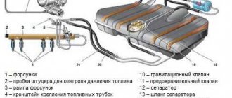
Diagram of the common rail diesel power system:
A modern nozzle is a compact but complex device.
A modern nozzle is a compact but complex device.
A modern nozzle is a compact but complex device.
The level of care with which the specialists fine-tuned the diesel engine’s working process is evidenced by its low noise level. Thus, preliminary injection before the main dose significantly softened the ignition of the mixture - this alone made CR diesels more silent than their predecessors. CR diesel engines also have post-injection. Its role is auxiliary - to clean the particulate filter. An additional portion of fuel, without burning in the cylinders, enters the filter and heats it to temperatures at which the soot is completely burned out.
WE REPAIR
Restoring the pump's functionality can only be done by a specialized workshop with qualified personnel and diagnostic equipment. The cost of repairs is from 7 thousand rubles, then it depends on the complexity. In case of some damage, it is wiser to buy a new injection pump. The usual price, about 30 thousand rubles, will shock the tight-fisted diesel operator, which is why repaired or restored products are in use.
A CR diesel with high mileage is often impossible to start due to a malfunction of at least one of the injectors. Fuel leakage through its valve does not allow the pressure in the rail to rise to starting values. There is a special diagnostic kit to check the pressure at start-up. It includes a control pressure gauge, a pressure sensor, connection tubes, plugs instead of actuators and backflow measuring containers.
Peugeot 406 2.0 Hdi Seven in the evening › Logbook › P1112. Insufficient pressure (leakage)
The problem has been present since the purchase and appears periodically. Of the 39 entries in the logbook, in at least seven I return to this problem. The bottom line is this: when accelerating sharply, the car stalls, not always, but at extremely unfortunate moments. But first things first.
It all started with a bad start, it was necessary to oil the starter for about 10 seconds. It stalled occasionally. Checking with the ELM 327 scanner showed two errors: - P0220 Accelerator pedal position sensor signal error: Compliance with the released pedal position (Another interpretation option: Malfunction of the throttle position sensor “B”); - P0230 Fuel pump relay control error: Circuit open (Option 2 : Malfunction of the primary control circuit of the fuel pump). I thought there was a problem with the pump in the tank. A pressure gauge was installed at the Inter service station (ChSUP AvtoritetAvto). They said that everything was fine - the pressure was 2.5 bar. But despite this, doubts about the pump remained - since it stalled with a small amount of fuel in the tank (less than a third on the scale on the dashboard) much more often. There at Inter they almost removed the fuel injection pump and sent it for inspection, but it didn’t come to that.
Over the past year, when scanning Lexia for engine errors, only one error appeared:
Another pattern discovered was that it often stalled while accelerating after turning to the right (every time I approach the turn from the shoe factory to the new bridge, I wonder if I will stall or not :().
Since the pressure drop in the ramp could also be due to the “return” of the injectors, I decided to check them. I made the following devices from 20 ml syringes and four droppers:
I did it alone, so I wasted a little time. But 10 ml is like the maximum permissible limit, it seems, but on all four forces it’s sad. So I think the check did not allow us to exclude the injectors as the culprit of the engine stall, and their time is coming. Is it possible that with high pressure in the rail, one of the injectors begins to drain heavily?
Also, in the spring, I began to worry about increased smoke during acceleration; this had not been observed before. The smoke is black, which again indicates a fuel problem. Since purchasing the car, I have refueled more often at Belneftekhim gas stations. On Andrey's advice, I decided to ride a Lukoil Ecto-Diesel. As a result, the smokiness decreased but still did not return to normal. But the correction of the injectors has improved significantly, it happened that when cold it was above 3 on the third injector, and the first and fourth were in the region of 2. Now everything does not exceed two.
I made screenshots of injector corrections at different engine temperatures, maybe someone understands this and can tell me what to do.
So the search for the causes of error P1112 continues. I would also like to figure out how to start the car - now it doesn’t seem to bother me, but it does appear from time to time. From the patterns I noticed that if you don’t wait a long time after turning the key to the second position and starting it, it picks up instantly. If you wait 5-10 seconds, it may not start, or it may take a long time to catch.
If anyone has any ideas, write, they will help a lot.
Source
A cutaway view of a high-pressure fuel injection pump with a plunger section shut-off valve.
It is reasonable to replace worn out injectors as a set. The price range is very wide: depending on the model and manufacturer, they cost from 8 thousand to 25 thousand rubles. a piece. The characteristics of each new injector must be recorded in the memory of the engine control unit, because no two injectors have the same performance. Different ones not only have a bad effect on the uniformity of engine operation and its dynamic loads, but also worsen the characteristics of the car. Although each ECU has dynamic adaptation (constant adjustment of the cyclic fuel supply for smooth engine operation), you need to remember that it cannot replace the coding if, for example, you forgot to write it down.
The problem of difficult starting of a diesel engine is one of the most common. And the owner is sometimes dissatisfied, for example, with reduced engine power or exhaust smoke. These problems are the most complex, because they require an assessment of the accuracy of measuring air flow or supercharging operation, the efficiency of recirculation, the exhaust gas system, including the diesel particulate filter (DPF) and the converter. However, these technologies are now well mastered by diagnostic masters.
Source
Coarse and fine fuel filters
Fuel is purified from mechanical impurities and water in coarse 9 and fine 3 filters. The coarse filter, installed in front of the main fuel pump 8, traps particles measuring 20...50 microns, which account for 80...90% of the mass of all impurities. A fine filter, placed between the main fuel pump and the injection pump, traps impurities with sizes of 2...20 microns.
Currently, the following types of coarse filters are used in diesel power plants:
- mesh
- tape-slit
- plate-slit
For mesh filters, the filter element is a metal mesh. It can be used to form concentric cylinders through the walls of which fuel is pressed, or disk-shaped sections strung on a central pipe with holes in the wall connected to the outlet pipeline.
In a slotted belt filter, the filter element is a corrugated glass with a profile tape wound on it. Through the gaps between the turns of the tape formed by its protrusions, fuel from the space surrounding the filter element enters the depressions between the corrugated glass and the tape, and then into the cavity between the bottom and the lid of the glass, from where it is removed through the outlet pipeline.
The filter element of a plate-slit filter is a hollow cylinder made up of identical thin annular disks with folded projections. Due to these protrusions, gaps are formed between the disks. The fuel flows to the outer and inner surfaces of the cylinder and, passing through the slots between the disks, is cleaned. The cleaned fuel is directed through the end holes in the disks to the upper part of the filter to the outlet.
Very often, a coarse filter is combined with a settling tank for water contained in diesel fuel. In this case, it is necessary to periodically unscrew the sump plug to remove accumulated water from it.
In fine filters, cardboard elements of the “multi-beam star” type or bags of cardboard and felt disks are usually used as filter elements. Less commonly used are frames with padding that absorbs mechanical impurities (for example, mineral wool), frames with fabric or thread winding, etc.
During vehicle operation, fuel filters become dirty, which leads to an increase in their resistance. To ensure that the fuel supply to the injection pump does not stop, it is necessary to periodically wash the coarse filter and replace the fine filter element with a new one.
Operating principle of a Common Rail diesel engine (CRDi)
The fuel systems of most modern engines use advanced technology known as CRDi or Common Rail Direct Injection.
The common rail direct injection system has one rail (fuel rail) that contains diesel fuel under high pressure.
It acts as a common fuel reservoir for all injectors. In the CRDi system, the fuel rail constantly accumulates and supplies fuel to the injectors of the solenoid valves, at the required pressure.
This system is completely opposite to the high pressure fuel pump (HPFP), which supplies diesel through independent fuel lines to the injectors, in earlier generation fuel systems.
CRDi technology works in tandem with the engine's Electronic Control Unit (ECU), which receives signals from various sensors. It then calculates the exact amount of fuel and injection timing.
The fuel system has components that are more intelligent in nature and are controlled electronically.
In addition, conventional injectors have been replaced with more advanced electromagnetic injectors. They are opened by a signal from the ECU depending on variables such as engine speed, load, engine temperature, etc.
With common rail direct injection, combustion occurs directly in the main combustion chamber, located in a cavity above the piston head.
Today, manufacturers are using CRDi technology to overcome some of the disadvantages of conventional diesel engines, which were sluggish, noisy and had poor performance.
CRDI is also known by different names, different brands which are given below:
CRDi (Common Rail Direct Injection System) - Hyundai and Kia
DDIS (Diesel Direct Injection System) - Suzuki, Fiat Group
TDI (turbocharged direct injection) -Volkswagen
TCDI (Turbocharged Common-Rail Direct Injection) - Chevrolet
TDCi - Ford, Jaguar, Land Rover Volvo and Mazda
MJE (multi-jet injection), JTDm, CDTi, TiD, TTiD, DDiS and Quadra jet - Fiat groups
i-CTDI and i-DTEC -Honda
Tier3, Tier4, 4D95 and higher HPCR series - Komatsu
Source
Diesel fuel
Diesel fuel is one of the products of oil refining. It contains various hydrocarbons (paraffins, naphthenes, aromatics, etc.). The number of carbon atoms included in diesel fuel molecules reaches thirty. The main quality of diesel fuel is its ease of ignition when in contact with hot air. The flammability of fuel is characterized by the cetane number. The higher this number, the less resistant the fuel molecules are to oxidation and the more easily it ignites. Diesel fuel has a cetane number of 40 - 50 (most often 45).
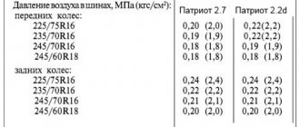
An important characteristic of fuel is also its viscosity at different temperatures. To ensure normal engine operation, fuel should not solidify at low temperatures (up to -60 ° C). In addition, it is necessary that the fuel is non-toxic, has anti-corrosion and lubricating properties, and does not create vapor locks in fuel lines at temperatures up to 50 ° C.
Automotive diesel engines use fuel grades A (Arctic), 3 (winter) and L (summer). The most widely used fuels are grades Z (at negative air temperatures) and L (at temperatures above 0 °C).