Lada Priora cars are equipped with two oxygen concentration sensors (hereinafter referred to as OCC). The top one is diagnostic, the bottom one is control.
The controllers are designed to determine the quantitative composition of oxygen in the exhaust gases for the purpose of subsequent adjustment of the ignition angle.
An excess amount of air in the fuel mixture, as well as an insufficient amount, negatively affects the functionality of the technical device. Most often, fuel consumption increases, passive acceleration dynamics, and unstable idling.
During systematic operation of the machine, refueling with low-quality fuel, the controllers fail. The process of self-replacement is not complicated, but requires attentiveness on the part of the master. Violation of the regulations is not acceptable.
Replacing the oxygen sensor on a Priora
Welcome! Oxygen sensor - also known as a lambda probe, whatever people call it, but still its only real name is the Oxygen Concentration Sensor, there are only two of these sensors on the Priora, unlike the VAZ 2114, VAZ 2110, etc. d. (They have one sensor each), but not all of them either, for example, if you take a VAZ 2114 car with 1.
6 engine, then there are also two oxygen sensors, on the VAZ 2110 with a sixteen-valve engine there are also two and on the Prior, as you have already noticed, there are also two, one of them acts as a diagnostic one and detects the burnt mixture and sends these readings to the controller (This is the ECU , it is also called the brain) and the other is used as a regulator and it already regulates the mixture of the car from start to finish, these sensors are located differently, that is, the diagnostic one is located after the catalyst, and the regulating one before it, you will find out more about this in detail in the article take a look.
Note! Replacement of both sensors is carried out if you have: Wrenches and gloves; of the wrenches, you will need to stock up on a “22” wrench with which you will unscrew the sensor!
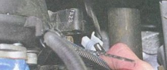
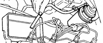
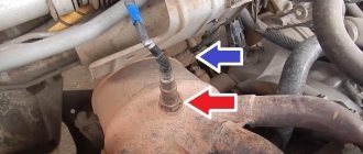
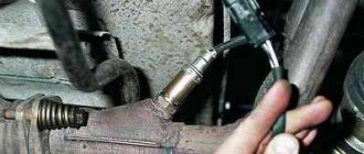
Where are the oxygen sensors located? Their location is on the exhaust manifold, they are screwed into it, to be more precise, there are two threaded holes in the manifold, one before the catalyst, the second after it, and so the regulating oxygen sensor is screwed into the first hole that goes to the catalyst (Indicated by a blue arrow ), by the way, it basically always fails, and a diagnostic sensor is screwed into another hole that goes after the catalyst, and for clarity, in the photo below this sensor is indicated by a red arrow.
When should oxygen sensors be replaced? Let's start with the diagnostic one, it is only needed so that the controller understands what state the manifold is in, provided that the regulating sensor is working properly, let's try to explain in simple words, for example, the car is working normally, all the sensors are working, but the catalyst is very clogged, the diagnostic sensor understands this because he stands behind it and determines whether the mixture after the catalyst is rich or lean, thus if he determines that something is wrong with the catalyst, then in this case the “Check Engine” lamp will light up, while the second sensor, regulating, already regulates the mixture and when it fails, the concentration of exhaust gases increases (All this is due to the fact that the mixture becomes rich, in simple words, blacker smoke will come out of the muffler than it was before and consumption will increase), throttle response deteriorates and the idle speed becomes uneven, lamp " Check Engine" in this case may or may not light up at all (It will light up only if the sensor is completely dead, but if it is on the verge of dying and is already giving incorrect readings, then this lamp will not light up).
Electric snag
The emulator has a microprocessor that corrects the signal for the ECU. The latter “believes” that the sensor is working and passes the data without interpreting it as an error.
In fact, there is no longer a catalyst in the design; instead, a section of the exhaust pipe is welded in.
The cost of the emulator varies from 1,500 rubles, which is 85–90% of the price of a new recreation center. Unlike a standard controller, the emulator has an unlimited service life.
| Catalog article/marking | Price in rubles |
| BOSCH 0 258 006 537 (8 and 16 valves) | From 1500 - 1600 |
| BOSCH 0 258 986 602 (8 and 16 valves) | From 1500 - 1600 |
| BREMI 30223 | From 1500 - 1600 |
| ERA 550489 | From 1500 - 1600 |
| DENSO DOX-0150 | From 1500 - 1600 |
| Metal spacer | 250-300 |
| Electronic emulator | From 1350 |
| *prices are as of May 2022 | |
How to clean a lambda probe
You can easily clean the lambda probe yourself, without additional equipment. It is advisable to do this after the car has been turned off for several hours. This will completely cool down the collector, which gets very hot when the engine is running. You can see where the lambda probe is located in the car's instructions; usually it can be easily seen on the manifold. First you need to disconnect the sensor from the circuit and unscrew it. It is advisable to disconnect the wiring from the sensor when the battery is disconnected. The sensor itself is unscrewed with a regular wrench. If the lambda probe is stuck and cannot be unscrewed with normal force, then the threaded connection can be filled with ammonia, kerosene or vinegar. After a few hours, the rust should dissolve and the sensor can be easily unscrewed. You can't knock on it. Firstly, you can break the sensor itself. Secondly, it will get stuck there even more tightly, the mounting thread will be damaged, and the manifold will have to be completely replaced. You can clean the lambda probe at home using phosphoric acid. You need to immerse the sensor in acid for half an hour, and then remove it and rinse well several times with warm water. Phosphoric acid should eat away any deposits that accumulate on the sensor.
Causes of failure
Old and new samples Before starting the test, it is necessary to determine the reasons why the sensor stopped working correctly.
- Coolant has leaked inside the device.
- Unsuitable cleaning agents were used to clean the body of the device.
- The gasoline you fill your car with contains large amounts of lead. A popular breakdown typical for cars of those owners who prefer cheap gas stations.
- A banal overheating of the heat-resistant sensor, which again occurs due to low-quality fuel.
Features of replacing the oxygen sensor on a Priora
In cases where the Priora oxygen concentration sensor has not solved the problem with the engine even after cleaning, it is necessary to install a new element. It's quite simple to do.
But if the owner decides to make another replacement after the car has run 90 thousand km, then he needs to remember that problems may arise when removing the controller. They can be solved in several ways.
Due to heavy carbon deposits, the sensor can become stuck to the mount. Then the contractor will need to treat the connection with WD-40 or lightly tap the sensor and mount.
An equally effective way can be to warm up the elements using a burner or any other tool. If after all the attempts on the Priora the oxygen concentration sensor is not removed, you should warm up the car well and then remove the element.
Replacing the sensor usually takes 30 minutes. Therefore, there is no point in delaying or postponing work. After installing a new controller, engine problems will disappear and fuel consumption will normalize. The abnormal functioning of the lambda probe cannot be ignored. It can lead to serious damage to the car and the need for urgent engine repair.
If you need not only the restoration of the functionality of individual elements of the exhaust system, but also its comprehensive adjustment, you can contact the VIHLOP-SYSTEM workshop, which repairs mufflers in the Southern Administrative District of Moscow.
Installation of blende
Perform installation only in specialized auto repair shops, as special equipment is required:
- Welding machine;
- Sander;
- Metal pipe;
- Flange connections.
The installation steps are as follows:
- Disable the current sensor;
- Cut out the catalyst on the exhaust pipe section;
- Weld the metal insert;
- Screw in the DC together with the spacer.
If the owner of a VAZ 2110 wants to install an electronic trick, then this will require flashing the ECU with a portable scanner.
How to repair a lambda probe?
Manufacturers of lambda probes position the parts as non-separable and cannot be repaired. However, some car owners, with some success, try to disassemble and repair sensors, assembling one functional one from two or more damaged devices.
The car owner should remember that such a lambda probe repair is a temporary measure. It is recommended to purchase a new sensor and use the repaired one as a spare.
Heating element repair
An approximate sequence for disassembling and repairing a sensor with a damaged heating element:
- Carefully saw through the outer housing of the sensor.
- The second sensor is sawed in a similar way.
- Remove the heating rods from the sawn housings. The entire device must be wiped from carbon deposits and dirt with a dry cloth. The use of cleaning agents is not recommended as chemical reactions may damage the heater.
- Install the heater into the probe that will be used on the car.
- Solder the body with copper-phosphorus solder, which has a melting point of about 700 ºC. A gas jewelry burner is used as a heat source.
- Check the functionality of the product with a tester and install the probe into the collector. If the repaired device does not work, you can try replacing the heater again. Below are photos that explain the repair process.
Repairing faulty wiring
There are recommendations for installing an additional resistor in the heating circuit if it fails. According to the authors' idea, the resulting resistance should give the correct signal to the control unit and turn off error information. In fact, this is what happens, but the lifespan of the additional resistance ranges from several hours to several days. A resistor that heats up to high temperatures can cause a fire in the engine compartment.
You can troubleshoot a broken wiring harness as follows:
- Saw through the housing on the top of the probe.
- Remove old wires completely, as the insulation wears out and cracks over time.
- Remove the pins with soldered wires from the donor block. Any available plug block can be used as a donor.
- For further work, it is necessary to remove the connecting elements from the pins.
- Assemble a new wiring harness using the standard rubber seal from the probe.
- Install the removed connecting elements onto the ends of the wires.
- Connect the wiring to the lambda probe response cables.
- Crimp the contacts and additionally solder them with refractory copper-phosphorus solder.
- Solder the housing and coat the place where the wiring harness enters the sensor with heat-resistant sealant.
When repairing the lambda probe wiring, it is recommended to check at each stage that there are no short circuits between the conductor and ground.
Cleaning from carbon deposits and soot
Another repair option is to clean the measuring element from carbon deposits and soot:
- Carefully cut off the protective caps.
- Soak the sensor in phosphoric acid, then carefully clean off the carbon deposits with a brush. It is not recommended to apply force as the measuring element is extremely fragile.
- If necessary, further clean the element by heating it on a gas burner. The procedure should be performed carefully, as the part may crack. Heating and cooling with cold water, which is recommended in a number of sources, is prohibited, since this will lead to complete failure of the probe.
- Reassemble the sensor by connecting the parts with refractory solder or spot welding.
Device diagram
Let's look at the probe diagram to give an idea of the node placement. Knowledge of the design allows you to understand the position of parts susceptible to failure.
Probe design example
- 1 - metal fitting, designed for installing a probe, there are turnkey edges on the outer surface, the thread is located at the bottom;
- 2 - ceramic insulator;
- 3 - sealing element for entering electrical wiring;
- 4 - signal cables;
- 5 - metal protective cap with ventilation ducts, designed to protect the measuring element from damage;
- 6 — spring contact part;
- 7 — ceramic sensitive element;
- 8 - heating rod;
- 9 - ventilation duct;
- 10 - outer metal casing.
Oxygen sensor for Lada Priora: original, analogues, price, catalog numbers
Despite the fact that the price of the original controller is slightly higher than 1,500 rubles, not many car enthusiasts are willing to buy factory spare parts. Cheap analogues are often preferred.
So-called “fake devices” are installed instead of standard sensors. After 90 - 100 thousand km. The Lada Priora catalyst becomes unusable, as evidenced by a number of signs. At the request of the client, the service station technicians remove (cut out) the standard catalyst from the exhaust system and replace it with a “dummy”.
Dummy exhaust manifolds are made according to the scheme: 4-2-2 or 4-2. Popularly called spiders. This is a one-piece design together with the exhaust manifold coupling and exhaust pipe.
To prevent the electronic control unit from identifying a system error, the lambda probe is replaced with one of the following types of decoys:
- Mechanical;
- Electronic.
Where to buy car accessories
Spare parts and other products for the car are easily available for purchase at auto stores in your city. But there is another option that has recently received significant improvements. You no longer need to wait a long time for a parcel from China: the AliExpress online store now offers the opportunity to ship from transshipment warehouses located in various countries. For example, when ordering, you can specify the “Delivery from the Russian Federation” option.
Follow the links and choose:
| Lambda probe, oxygen sensor for Lada Samara, Kalina, Priora | Eunavi s car alarm system, central kit with remote control | Car radar detector YASOKRO V7, 360 degrees |
| Radar detector Karadar STR G820 Led 2 in 1, radar detector with GPS | Auto radar detector 12V | Digital air/fuel ratio sensor Dynoracing for Lada Priora |
How to check with a multimeter
The tester can check the operation of the heating component of the oxygen sensor:
- The diagnostic device switches to the resistance parameter measurement mode.
- The probes of the device are connected to the heater contacts. These elements are usually made of cable with a large cross-section.
- The contacts of the heating device are ringing.
- If the heating element is working, then the resulting resistance value will be less than 10 ohms. If this parameter is higher, then the electric heating device has failed and needs to be replaced.
The tester checks like this:
- Locate the controller mounting location under the hood of your vehicle.
- Connect the multimeter probes to the signal outputs of the sensor or electrical circuits. The tester itself sets the measurement limit to 2 volts.
- At the next stage, it is necessary to artificially create a situation of an over-enriched combustible mixture. To do this, you can use the throttle change method by periodically pressing the gas pedal. Or you can remove the pressure sensor connector.
- Then the readings given by the tester are read. Ideally, they should be from 0.8 volts, this indicates that the oxygen sensor is working properly.
- It is necessary to artificially create a lean mixture situation. To do this, you can create an air leak by slightly loosening the air duct clamp. With a lean mixture, the tester reading should be no more than 0.2 volts.
V_i_t_a_l_y talked about diagnosing the oxygen controller using a multimeter.
Visual inspection
The check should always begin with a visual examination of the condition of the oxygen sensor.
- Inspect the wires. They must be intact, without traces of damage or defects. Check all connectors for tight connections.
- Soot on the lambda probe indicates a malfunction of the device heater. Also, such deposits are caused by an excessively rich air-fuel mixture.
- If you notice shiny deposits on the surface of the element, this indicates an excess of lead in the fuel you are filling the tank with. This situation requires mandatory replacement of the oxygen sensor, since lead could damage the internal device.
- Gray or white deposits are the result of various types of fuel additives affecting the sensor. They often cause the probe to break and have to be replaced.
Assignment of contacts of Bosch ME17.9.7 ECU
The table shows the assignment of contacts for controllers 21126 – 1411020-40, 11194 – 1411020-20. The difference in connection for controllers 21214 – 1411010-50 is highlighted in blue.
| № | Output purpose | № | Output purpose |
| Section X2 | Section X1 | ||
| 1 | Entrance. Crankshaft Position Sensor B | 1 | not connected |
| 2 | Entrance. Oxygen sensor 2 | 2 | not connected |
| 3 | Entrance. Other damper position sensor 1 | 3 | Weight of analog sensors |
| 4 | Weight of DC 1 | 4 | Weight of analog sensors |
| 5 | Weight of DTOZH | 5 | Accelerator pedal sensor 1 ground |
| 6 | Weight of DK 2 | 6 | Accelerator pedal sensor 2 ground |
| 7 | Weight of other damper position sensors | 7 | Refrigerant pressure sensor input (level 2) (not used) |
| 8 | Air flow sensor weight and temp. air | 8 | not connected |
| 9 | not connected | 9 | not connected |
| 10 | not connected | 10 | not connected |
| 11 | not connected | 11 | Accelerator pedal sensor 2 |
| 12 | not connected | 12 | not connected |
| 13 | Entrance. Crankshaft position sensor A | 13 | not connected |
| 14 | not connected | 14 | not connected |
| 15 | Entrance. DTOZH | 15 | Exit. Main relay |
| 16 | not connected | 16 | Entrance. Ignition switch terminal 15 |
| 17 | not connected | 17 | not connected |
| 18 | not connected | 18 | not connected |
| 19 | not connected | 19 | Entrance. Refrigerant pressure sensor (1 and 3) level (not used) |
| 20 | Entrance. Other damper position sensor 2 | 20 | not connected |
| 21 | not connected | 21 | Entrance. Accelerator pedal sensor 1 |
| 22 | not connected | 22 | Entrance. Fan diagnostics (not used) |
| 23 | Power supply (3.3V) for other damper position sensors | 23 | not connected |
| 24 | not connected | 24 | not connected |
| 25 | not connected | 25 | not connected |
| 26 | not connected | 26 | Power (3.3V) accelerator pedal sensor 2 |
| 27 | Entrance. Intake air temperature sensor | 27 | K‑Line |
| 28 | not connected | 28 | Exit. Tachometer |
| 29 | not connected | 29 | Exit. Fuel consumption signal |
| 30 | Entrance. Oxygen sensor 1 | 30 | not connected |
| 31 | Entrance. Camshaft position sensor | 31 | Exit. A/C relay (not used) |
| 32 | Entrance. Vehicle speed sensor | 32 | CAN‑H |
| 33 | Entrance. Mass Air Flow Sensor Input. Air flow sensor (frequency) | 33 | not connected |
| 34 | not connected | 34 | Entrance. Request to turn on the air conditioner (not used) |
| 35 | Exit. Canister purge valve | 35 | Entrance. Brake pedal switch 1 |
| 36 | not connected | 36 | Entrance. Clutch pedal switch |
| 37 | Entrance. Knock sensor – terminal 1 “+” | 37 | Power supply (5V) air flow sensor |
| 38 | Entrance. Knock sensor – terminal 2 “-” | 38 | Power supply (3.3V) accelerator pedal position sensor 1 |
| 39 | Exit. Heater DK 2 | 39 | not connected |
| 40 | not connected | 40 | Exit. MIL warning lamp |
| 41 | not connected | 41 | Exit. Fan relay 1 |
| 42 | Exit. Injector 2 cylinders | 42 | Exit. Fuel pump relay |
| 43 | Exit. Injector 3 cylinders | 43 | not connected |
| 44 | Exit. Injector 1 cylinder | 44 | CAN‑L |
| 45 | Exit. Injector 4 cylinders | 45 | not connected |
| 46 | Exit. Heater DC 1 | 46 | not connected |
| 47 | Weight of sensors Weight of electronics | 47 | Brake pedal switch 2 |
| 48 | not connected | 48 | not connected |
| 49 | not connected | 49 | not connected |
| 50 | Weight of output stages | 50 | not connected |
| 51 | Exit. Throttle valve drive 1 “+” | 51 | Exit. Starter relay |
| 52 | Exit. Throttle valve drive 2 "-" | 52 | Exit. Fan relay 2 |
| 53 | Ignition coil 2 cylinders (not used) | 53 | Weight of output stages |
| 54 | Ignition coil 3 cylinders Ignition coil 2.3 cylinders | 54 | Weight of output stages |
| 55 | Ignition coil 4 cylinders (not used) | 55 | Output +AB after the Main Relay |
| 56 | Ignition coil 1 cylinder Ignition coil 1.4 cylinders | 56 | Output +AB after the Main Relay |
What does it consist of?
Oxygen sensors for Lada Priora consist of:
- metal case;
- four-pin connector for connecting electrical wiring:
- external electrode (platinum);
- internal electrode (zirconium);
- electrode insulator (ceramics);
- sensor electric heater;
- protective casing of the external electrode.
The lambda probe elements are resistant to high temperatures, as well as to its constant changes. This is due to the fact that its installation location is the engine exhaust system, some areas of which heat up to 900 °C.
How to identify and eliminate problems with the Priora oxygen sensor?
Operation is checked using an oscilloscope. It is also possible to visually assess the condition, but the accuracy of certain problems will be minimal.
When inspecting the sensor, pay attention to the amount of carbon deposits. If the layer is even and very dark, then most likely the lambda probe should be replaced
The average and high price of the Priora oxygen sensor should not prevent you from repairing the lambda probe. Otherwise, the owner will need a larger investment in engine restoration.
Cleaning a ceramic rod can be done in several ways. The first of them is a chemical effect on carbon deposits and washing it with a special composition. The second is simpler and involves heating and sharply cooling a ceramic rod. True, the second method is less effective, so it should be used only in extreme cases.
To carry out chemical cleaning, you will need to purchase phosphoric acid, which does not leave a film. Otherwise, deposits on the sensor will appear again. The protective caps must be temporarily removed, or rather carefully cut off. Next, the ceramic rod is immersed in acid for about 15-20 minutes, and then simply dries.
For the second method, you can use a portable burner. The rod is held above it for literally a couple of minutes, then it is moved into the cold.
If there is no suitable portable refrigerator at hand or it is not possible to create cold, then the sensor is simply removed from the fire for a couple of minutes. With several repetitions of the procedure, the deposit simply falls off the rod. After the work is completed, the caps are installed in place and carefully welded in the cut areas.
Symptoms of malfunction
Where is it installed?
Based on the behavior of the car, you can easily determine that the lambda probe has become unusable:
- The car jerks while driving;
- The revolutions are floating;
- The catalyst is not working properly;
- Fuel consumption increases noticeably;
- Exhaust gases contain a large amount of toxins.
The operation of this sensor requires constant monitoring. According to the operating manual, the check is performed every 10 thousand kilometers traveled. But if the operating conditions of the car are difficult, you have to regularly drive in difficult conditions, or the engine is overloaded, then it is better to check it more often.
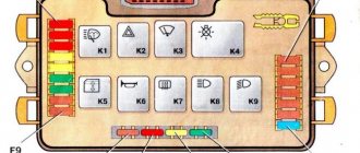
LADA PRIORA 21723
Assignment of contacts of the instrument cluster block
1 To the electric power steering 2 To the hazard warning lamp 3 To the emergency oil pressure sensor 4 To the parking brake switch 5 To the immobilizer control unit 6 To the airbag control unit 7 To the exterior lighting switch 8 To the turn signal switch (starboard side) 9 To the indicator switch turn (left side) 10 To the fuel injection system control unit 11 To the front passenger airbag deactivation sensor 12 To the seat belt sensor not fastened 13 To the control unit of the electronic brake force distributor 14 To the “RESET” button on the steering column switch (-) 15 To the level sensor brake fluid 16 To the control sensor of the anti-lock braking system 17 To the high beam switch 18 To the instrument cluster lighting switch 19 Housing 20 To terminal “30” of the battery 21 To terminal “15” of the ignition switch 22 To the fuel consumption sensor 23 To the function switching mode key trip computer in a ring forward and changing the minutes (-) 24 To the mode key for switching the functions of the trip computer in a ring back and setting the clock (-) 25 To the outside temperature sensor (-) 26 To the outside temperature sensor (+) 27 To the fuel level sensor 28 To the speed sensor 29 To the coolant temperature sensor 30 Low-voltage tachometer input 31 Diagnostics during production of the instrument cluster 32 To the “L” terminal of the generator relay regulator
List of elements of the electrical connection diagram of the rear wiring harness of LADA PRIORA
1 – rear wiring harness block to the instrument panel wiring harness block; 2 – rear wiring harness block to additional wiring harness block 2 (left rear door); 3 – rear wiring harness block to side door wiring harness block (right front door); 4 – left side direction indicator; 5 – electrical package controller; 6 – right side direction indicator; 7 – interior lighting unit; 8 – handbrake warning lamp switch; 9 – left lamp; 10 – right lamp; 11 – interior air temperature sensor; 12 – interior lamp switch in the driver’s door pillar; 13 – switch for the interior lighting in the pillar of the right front door; 14 – switch for the interior lighting in the pillar of the right rear door; 15 – interior light switch in the left rear door pillar; 16 – block of the rear wiring harness to the block of the wiring harness of the side doors 2 (left front door); 17 – block of the rear wiring harness to the block of the additional wiring harness (right rear door); 18 – blocks of the rear wiring harness to the rear right loudspeaker; 19 – blocks of the rear wiring harness to the rear left loudspeaker; 20 – cigarette lighter; 21 – electric fuel pump module; 22, 23 – rear wiring harness blocks to instrument panel wiring harness blocks 2,3; 24 – trunk lighting; 25 – additional brake signal; 26 – trunk lock drive switch; 27 – interior lamp; 28 – rear wiring harness block to the front wiring harness block; 29 – left rear speed sensor; 30 – right rear speed sensor; 31 – sensor for automatic glass cleaning system (rain sensor); 32 – rain sensor sensitivity regulator; 33 – rear wiring harness block to instrument panel wiring harness block 4; 34 – block of the rear wiring harness to the block of the wiring harness of the parking system sensors; 35 – alarm unit for safe parking system; 36 – driver’s seat belt pretensioner; 37 – passenger seat belt pretensioner; 38 – rear wiring harness block to side door wiring harness block 3 (right front door); 39 – airbag control unit; 40 – parking system control unit; 41 – block of the rear wiring harness to the block of the rear additional wiring harness (tailgate); 42 – rear wiring harness block to rear additional wiring harness block 2 (tailgate); 43 – left seat heater; 44 – switch for electric seat heaters; 45 – right seat heater. 46 – rear wiring harness block to the parking system switch.
Repair
The types of work performed depend on what signs of malfunction were identified during the diagnosis.
Wiring repair
If visible or internal violations are detected, the wiring must be repaired or replaced.
Connector repair
In case of mechanical failure of the connector, it must be replaced, since it will not provide insulation of the connected contacts.
If the connector becomes oxidized, it must be reconnected and the contacts cleaned.
Cleaning (temporary measure)
During the operation of the vehicle, a significant layer of carbon deposits accumulates on the surface of the sensor.
Cleaning is carried out using phosphoric acid and a brush made of soft material. The outer electrode and protective casing must be soaked for about 20 minutes until the accumulated carbon deposits are removed, or cleaned with a brush.
It is not recommended to use products made from hard materials, for example: metal brushes, screwdrivers, sandpaper.
After cleaning, the lambda probe must be completely dried.
Replacement
Replacing the first or second sensor consists of the following steps:
- disconnecting the connector;
- removing the lambda probe from the exhaust system;
- installing a known-good sensor;
- connector connection.
After repairing, cleaning or replacing the elements of the lambda probe, it is necessary to recheck its operation by starting the engine and warming it up to operating temperature.