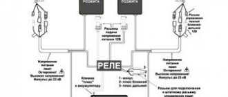
The procedure for connecting high-voltage wires on a VAZ 2109 (carburetor, injector)
The ignition module on injection VAZ 2109 is deservedly considered one of the most complex electrical components. If the injectors have a module, then the carburetors have the simplest coil.
The actual, but incredibly important task of the module is the generation of high voltage current, which can reach 30 thousand watts. The current follows high-voltage wires to the spark plugs, which create a spark to ignite the air-fuel mixture.
The classic ignition coil is one of the components of the module, so the system works on a much more complex principle than on carburetors.
Features of the ignition module
Now let's talk about a more complex issue - the ignition module and its design features.
The design includes several components, each of which has its own nuances.
| Component | Peculiarities |
| Ignition coil | There are always two coils on a VAZ 2109. This mechanism is responsible for generating current |
| High voltage switches | Switch keys also work together. Through them, the current goes to the spark plugs, plus the controller regulates the time the current is turned on, which is calculated by receiving information from the crankshaft sensor |
| Electronic control unit | Responsible for distributing information in the form of electronic impulses |
| Frame | High-strength plastic is used for its manufacture, which largely ensures the durability and reliability of the device. |
Ignition coil
Location
Any work related to repair, testing, and maintenance of the ignition module will be impossible to perform if you do not know basic things - the location of the device.
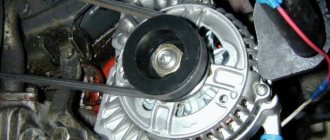
You can find the ignition module (ignition module) in the engine compartment. Find the high voltage wires that go to the spark plugs. One end is connected to them, and the other goes to the module. The MZ is small in size and enclosed in a plastic housing.
Device location
Principle of operation
Initially, on carburetor cars, the system worked due to the presence of an ignition coil. With injectors everything is somewhat different.
- Initially, the ignition coil is turned on, generating a high voltage current. The coil operates on the principle of magnetic induction;
- Then the electronic control unit MZ is connected to the work, performing the functions of control, transmitting commands, and ensuring the flow of current required by the characteristics to the spark plugs;
- Next, the spark plugs activate the spark, ignition occurs, and so on.
How to check the ignition on an injector
First you need
o will conduct a full computer diagnostic of the system. If problems are found, the on-board computer ( ] - “computer”) is a device or system capable of performing a given, clearly defined, changeable sequence of operations
) will indicate them by way (
place, direction or the process of movement (or change); up to the scientific abstractions of this concept: Path - a system of communication along which passage or travel is carried out, along which
) red indication (
methods and techniques of observation, recording, control, characterization and assessment of the state and stages of development of various processes, objects and research systems to establish and control dependencies on
) “Check”.
Pushcha ( forest (indigenous forest, primary forest, primeval forest, pushcha) - a forest that has not been changed by human activity and natural disasters
) the whole reason for the breakdown (
toponym in Russia
) is not the electronic ignition module, but problems with the damper (
technique - a device for shutting off openings and pipelines: Damper - a valve for closing a chimney or ventilation duct Damper - a cover for closing the inlet of a furnace or
) throttle assembly (
a method of connecting and protecting linear material, for example, rope, by tying and weaving
).
Here you will need a multimeter with which you need to measure voltage ( Electrical voltage between points A and B - the ratio of the work of the electric field when transferring a test charge from point A to B to the value of this test charge
) in a system ( a set of elements that are in relationships and connections with each other, which forms a certain integrity, unity
).
After ( high-ranking diplomatic representative of his state in a foreign state (in several states concurrently) and in an international organization; official representative
) turning the key in the ignition system, indications (
testimonies are information expressed in oral responses of witnesses about circumstances relevant for consideration and resolution of the court case
) of the device must be the following:
- total voltage of the on-board circuit is 12 V;
- The throttle valve sensor readings are 0.5 V, while the throttle valve is open only 1%.
Lada 2109 › Logbook › Dual-circuit ignition on the VAZ 2109
I suffered several times in the winter with starting the engine. Even when it’s not cold, but at 0 degrees, you come to start it and the car is silent. You unscrew the damp spark plugs and the battery eventually dies! With a good battery, it starts normally. As it turned out in the end, I had a contact ignition coil B- 117 from the classics. I immediately changed it to a coil from BSZ. And the car started to start and drive much better, but I didn’t stop there and decided to make a dual-circuit ignition with 2 hall sensors, 2 switches and 2 coils from the Volga ZMZ- 406
To begin with, I started assembling the distributor because it is the most basic and thinnest part of the system. I took the distributor from OKI as a basis, or an ordinary nine-wheel one. I just had it from the window lying in the garage. I completely disassembled it and started installing the second one. hall sensor directly to the standard platform at an angle of 90 degrees. Marked the approximate position of the 2nd sensor. On the platform there are risks of the approximate position of the middle of the sensor:
Drilled and tapped the threads for the bolts:
Then I carefully cut the hall sensors themselves with a metal cloth so that they do not interfere with each other. It looks something like this:
Then I modified the shaft, replaced the ignition angle advance weights with nine-shaft ones. They are smaller and lighter than those of the Oka, the photo shows Okushinsky weights! And accordingly, I also replaced the springs. The curtain remained the standard Okushinsky one, I didn’t touch it. If you make it from a nine-shaft shaft, then the curtain must also be modified sawing off two opposite ones so that it looks like in the photo:
That's all for the shaft! Next, I cut out a small piece from the distributor body itself to attach the fork of the 2nd hall sensor, drilled a hole and cut a thread for the bolt
Then I put the whole thing together. Here’s what happened:
Note: during assembly it turned out that the platform on which the hall sensors are attached from the Oka is larger than from the 2109 and it turned out to be easier to mount the sensor, so another one +, It is advisable to buy the same sensors themselves in the same store from the same batch as they are slightly different! That's all for now with the distributor!
Then I bought the rest of the necessary parts: 2 coils from the Volga ZMZ-406, a wiring harness for the BSZ 2108, an “Astro” switch, as I already had the same one
I connected the wiring according to the diagram:
Note: when connecting according to scheme 1, the tachometer will show half the revolutions. If you want to make a normal tachometer, then there is also scheme 2, you will need to solder in 2 KD213A diodes. But I did not do this and did it according to scheme 1. And don’t try to connect wires without diodes according to scheme 2; thereby you parallel both coils and it turns out that all 4 spark plugs spark at the same time when both hall sensors are triggered! Tested personally)
I made a metal mount for the coils, but it didn’t turn out very well:
And now about the most important thing: for the system to work well, you need to adjust the synchronization of the hall sensors so that the spark on all cylinders is the same advance. To do this, you need to make the opposite mark on the flywheel, this will be the TDC of the 2nd cylinder. You need to count 64 teeth along the crown from the standard mark. And Using a strobe light, align both marks from the 1st and 2nd cylinders, moving the 2nd hall sensor up and down or both sensors in the direction of the white arrows. To do this, I drilled holes with a thin drill in the sensors to move.
How to check high voltage ignition wires?
Checking high-voltage ignition wires for breakdown is carried out in one of three ways.
Visual inspection is the easiest way to check and detect damage to the insulating layer of high-voltage wiring. During this check, you need to make sure that there are no cracks, cuts or noticeable abrasions on the insulation surface. A breakdown can be visually determined by sparking. To do this, in the dark, just open the hood of the car, start the engine and turn off the lights. An insulation breakdown will be noticeable to the naked eye by sparks running through the wiring.
It is often impossible to visually determine that the high-voltage ignition wire is faulty. In such cases, the old proven method is used, which consists of the following steps. The engine is started and left to idle. Next, the contacts are removed one by one from the spark plugs and then put back on. All operations must be performed with rubber gloves, without touching the car body with your body. The conductor is faulty if, when it is disconnected from the spark plug, engine operation does not change.
The next method is to use a piece of wire stripped at both ends. The check is carried out at night with the engine running. One end of the segment is connected to the car body (“ground”), the other end must be driven along the high-voltage ignition wiring. If a spark appears when carrying out insulation, there is a breakdown in this place. This way, not only the insulation is checked, but also the plastic protective caps.
Checking high-voltage ignition wires with a multimeter
Car owners usually measure voltage with a multimeter, but the same device can also determine resistance, which is very useful when checking. To measure, high-voltage ignition wires are first disconnected or completely removed. The multimeter needs to be switched to resistance measurement mode, then the probes of the device need to touch the two ends of one wire. The device will show the measured value.
If, as a result of the test, one conductor turns out to be faulty, the rest will soon fail. Therefore, replacing the high-voltage ignition wiring is done as a set, rather than as separate wires. These products most likely will not be sold to you separately.
3 Tips for Selecting High Voltage Ignition Wires
Tip #1.
Carefully study the information about the product (manufacturer, terms of use, etc.) - it should be available both on the packaging and on the product itself.
Often, on fakes, the English word “silicone” is misspelled. This phenomenon is so widespread that it was even found in one authoritative print media on automotive topics. The authors mistakenly and without verification used the word “silicon,” which actually translates as “silicon.”
Tip #2.
Evaluate the quality of caps on high-voltage electrics.
The caps are made of silicone rubber; they are necessary to protect the wiring contacts and ensure the tightness of the connections. The minimum wall thickness of the cap is 3 mm. As inspection often shows, the electrical circuit is broken precisely at the junction of the conductor terminal with the contacts of the ignition system elements. This usually happens when the wiring is removed inaccurately or when there is a poor connection with parts of the ignition system due to poor fit, oxidation processes, etc.
Tip #3.
Evaluate the quality of the highest voltage ignition wiring.
Silicone products are of the best quality today. There are several simple ways to check their quality. For example, you can expose the cable to open fire. If the insulation is of high quality, it will not be easy to melt or even ignite it. Another way to check is to twist the wire tightly. If displacement or sliding of the core relative to the cable sheath is felt, and a characteristic crunching sound occurs, it means that the adhesion of the sheath to the insulation is poor. Also try moving the insulation layer along the conductor. There should be no displacements during testing; the cable must be solid. Otherwise, when installing or dismantling the wiring, the protection may be impaired.
Useful materials about cars
here!
Source
High voltage wires
According to our information, SLON high-voltage wires have been installed from the factory on domestic cars for three years now. Salespeople in auto parts stores say the same thing. Resistance from wires 1 to 4 is: 4.24-4.74-5.19-7.60. Passed the breakdown test at 40 kV. The price for high-voltage SLON wires is approximately 480 rubles.
Country of origin: Belgium. They have resistance from cylinders 1 to 4: 6.17-6.57-7.52-9.89 kOhm. The breakdown occurred at around 35 kV. The price for Ween high-voltage wires is approximately 260 rubles.
Cezar
Country of origin: Russia. Resistance from cylinders 1 to 4 is: 3.10-3.53-4.23-5.34 kOhm. Passed the breakdown test at 40 kV. Estimated cost: 450 rubles.
Tesla
Country of origin: Czech Republic. Tesla high-voltage wires have a resistance from cylinders 1 to 4 of 3.27-4.16-5.02-6.26 kOhm. Passed the breakdown test up to 50 kV. The cost of Tesla high-voltage wires is 450 rubles.
Country of origin: Russia. The wire resistance is 3.15-3.90-4.09-6.24 kOhm. The breakdown test passed up to 40 kV. The price for Horse high-voltage wires is approximately 360 rubles.
What can multiple misfires lead to?
Single misfires are only a signal to the owner of a VAZ 2114 about problems with the engine.
Numerous incidents entail the following consequences:
- As a result of misfires, unburnt fuel will enter the catalytic reduction system. Because of this, the converter will overheat and fail.
- With repeated misfires, some of the gasoline will enter the lubrication system through the walls of the idle cylinder. Oil diluted with gasoline will lose its properties and will not be able to provide high-quality lubrication of loaded engine elements.
- All these factors can lead to engine failure and the need for expensive repairs.
Signs of malfunction of high-voltage ignition wires
Evidence that the ignition cables have become unusable are the following signs:
- difficulty starting the engine, especially in wet weather;
- At medium and high speeds, unstable engine operation is noted;
- the engine does not develop full power;
- increased fuel consumption is observed.
As a rule, when there is severe wear on the wire insulation, many microcracks appear, due to which current leakage occurs. As a result, the wire is not able to transmit to the spark plug a current that is sufficient in magnitude for its normal operation. This significantly increases the spark generation time and interferes with the correct operation of the engine cylinders.
Quite often there are cases when wires are damaged as a result of contact with any engine elements. Situations of loss of cap tightness are also possible, and as a result - oxidation of contacts and current leakage. Regular cleaning of contacts is a mandatory procedure, especially when operating a vehicle in difficult climatic conditions.
How can a car owner check the wires for leaks? In fact, everything is very simple: in a dark garage, open the hood and start the engine. Leak areas will glow quite brightly in blue. There is a slightly different method: instead of a spark plug, a spark gap is installed (two electrodes in one housing) and the energy supplied to the spark plug is controlled using it.
In order to increase the durability of the insulation, it is recommended to monitor and constantly keep it clean. The contacts between the spark plugs and each wire are also subject to constant checking and cleaning.
High voltage wires
What are the dangers of ignition malfunctions?
The optimal operation of the entire AP depends on the performance of all its elements, as well as the set torque. In practice, carburetor internal combustion engines require more precise adjustment.
We suggest that you familiarize yourself with the problems in more detail:
- The power unit detonates. When the driver presses on the gas, ringing sounds begin to be heard from under the hood. In practice, such problems appear in vehicles due to the timing being set too early. As a result, this causes the internal combustion engine to malfunction, and this can subsequently lead to deformation of the piston rings.
- When the engine starts, black smoke comes out of the exhaust pipe. Such problems usually indicate that the advance angle is set incorrectly, the timing is too late. Of course, correct adjustment will allow you to get rid of this problem.
- When idling, the power unit oscillates and operates unevenly.
- The internal combustion engine operates intermittently, when the driver presses the gas, dips appear. That is, the driver presses on the gas, but the car does not accelerate.
- The power of the power unit has decreased, that is, it takes much more time to gain speed. This problem may be due to the fact that the fuel-air mixture does not completely burn in the cylinders of the internal combustion engine.
When such problems occur, the car owner should start diagnosing the SZ, and if necessary, adjust the torque. In practice, most malfunctions are associated with this. But before you start making adjustments, you need to make sure that all components are working correctly. It is necessary to diagnose the spark plugs, the condition of the high-voltage wires, the coil and the distributor. Only if all these elements are intact, you need to start adjusting.
Features of connecting high-voltage wires to the VAZ 2114
High-voltage ignition wires of the VAZ 2114 are part of the ignition system, through which an electrical impulse is transmitted from the module to the spark plugs. When the current hits the spark plugs, the fuel mixture ignites in the combustion cylinders, which gives rise to a new stroke of the engine.
BB wires must be of high quality
The design of the GDP, unlike conventional wires, is quite complex. In addition to the conductive core (which is made of copper) and protective insulation, they have metal tips and plastic protective caps.
Metal tips act as contacts; they fit into the sockets on the spark plugs and the ignition module. The durability of the GDP directly depends on how well the tips are made. When purchasing, be sure to check the strength of their attachment to the wire.
General information about the Nine ignition system
The ignition system in the 21099 injector or carburetor is a collection of many components and mechanisms interconnected with each other. The main purpose of the SZ is to produce an electrical discharge, which is subsequently used to ignite the fuel-air mixture in the engine cylinders. One of the main parameters of the SZ is the moment of appearance of this discharge, that is, a spark, since it is this parameter that determines the correct operation of the power unit.
What elements does the SZ electrical circuit include:
- Coil or module. This device generates a high-voltage discharge and transmits it to the spark plugs via high-voltage cables.
- Candles. These devices are used to transmit a high-voltage pulse to the cylinders of the power unit, where the fuel-air mixture is located. Spark plugs may not work correctly over time, due to wear or carbon deposits on the electrodes. Such problems can lead to incorrect operation of the engine in general, as well as difficulty starting it in particular.
- High voltage wires. They connect the distribution unit with the candles. The performance of high-voltage wires is also important, since if they break down, the driver may also experience incorrect functioning of the internal combustion engine.
- Switchgear. This unit distributes the high-voltage discharge to certain spark plugs, since the cylinders must fire in a certain order. One of the main components of the distributor is the vacuum regulator.
- Switch.
- Mounting block.
- Ignition relay.
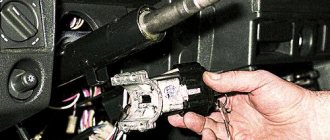
- A switch, that is, a lock. With its help, the driver gives the command to start the engine (the author of the video is Nail Poroshin).
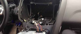
Wiring replacement process
Before the VAZ 2114 armored wires are replaced, it is necessary to remove the old cables. To do this, you should: 1. Turn off the engine ignition. 2. Open the car hood. 3. Remove the old wiring leading to the engine and ignition unit. To maintain the order of connecting high-voltage wires of the VAZ 2114, you must be guided by the following diagram:
Cylinders are numbered from left to right. In the module, the internal ignition cylinder 1 is located on the lower left side. The second and third cylinders are located in the left and right compartments, respectively. The output of the fourth cylinder is located at the bottom in the right compartment.
How to check high voltage wires
Finding high-voltage wires under the hood is not difficult, and diagnosing them is not fraught with any difficulties. There are three ways to check high-voltage wires, each of which allows you to determine whether there is a breakdown in them.
Visual diagnostics
The easiest way to check spark plug wires for insulation damage is to visually inspect them. It is necessary to carefully check that there are no cracks, cuts or severe abrasions across the insulation area.
Another way to visually check spark plug wires is to observe their operation at night. It is necessary to open the hood of the car at night, start the engine, turn off the headlights and watch the high-voltage wires. If they have strong insulation breakdowns, in the dark the “crickets” will be visible to the naked eye.
This is interesting: Reasons why there is no spark on a 4T scooter
Wire check
To check the spark plug wires, an ordinary wire with stripped ends on both sides can be used. In the dark, with the engine running, it is necessary to short-circuit one part of the wire to ground (car body), and run the other part along high-voltage wires in search of a place where the stripped tip will begin to produce a spark.
It is important to check not only the insulating material around the conductor, but also the plastic caps
Diagnostics with a multimeter
A multimeter in automotive diagnostics is most often used as a voltmeter, but it also has another useful function - the ability to measure resistance. To take measurements, you must completely remove the high-voltage wires (or disconnect one wire on both sides). Next, with the probes of the device set to ohmmeter mode, you should touch both sides of the wire, as a result of which the multimeter will display information about the resistance.
The resistance of serviceable high-voltage wires is up to 10 kOhm. At the same time, it can vary practically from zero. This depends on the type of wires themselves, the insulation used in them, the length, the presence of microdamages, and so on.
How to check
A new or used hall sensor for VAZ 2108-2109 can be checked. The most common are 3 methods: connecting another DC, diagnostics with a multimeter and the simulation method.
- For the easiest method, you will need a new or used HH. Disconnect the power supply from the sensor on the distributor and connect it to a separate DC. Remove the center wire from the distributor cap and place it on ground so you can see the spark. Turn on the ignition. Use a knife or thin screwdriver to move from side to side inside the magnetic element, simulating the operation of the screen. If there is a spark, then the DC is working, and if not, then it is defective.
- For this method you will need a multimeter, which must be converted into a voltmeter. If you carry out diagnostics outside the car, you will need a power source. This could be a 6 V motorcycle battery, a 9 V Krona battery, or a laboratory device on which you can make a low voltage of 4–9 V so as not to spoil the DC. The sensor has 3 contacts at its output. They are arranged in the following sequence: + / 0 / − (plus, pulse and minus). We connect plus and minus from the power source. Take the negative probe of the multimeter and attach it to ground. Insert the positive probe of the tester. If you move inside the sensor from side to side with a screwdriver or a knife, simulating the operation of the screen, then the voltage on the tester display should change from 0.4 V to 11 V. If so, then the DC is working.
- There is another way to check the hall sensor on a VAZ 2109 (carburetor), but without a multimeter. The method is called imitation. Applicable in the absence of another household. The process looks like this: disconnect the power supply from the sensor. Then remove the center high voltage wire from the distributor and place it on the engine ground so you can see the spark. Next, you need to close pins “3” and “6” on the switch with a jumper and watch for the spark. If it slips, then the sensor is faulty, and if it is not there, then the problem is somewhere else (wires, switch, etc.).
OPERATIONAL CHECK
To accurately determine whether it is time to change the high-voltage wires of the VAZ, you need to check their performance with a multimeter.
This operation will take you no more than 15 minutes:
- Turn off the ignition;
- We remove the wires: disconnect the first end from the ignition module, the second from the cylinder;
- We switch the tester to ohmmeter mode and connect the multimeter probes to the wire contacts.
If the high-voltage wires on the VAZ 2114 are in normal technical condition, the multimeter will show a resistance within the value indicated on the wire insulation; if the readings are different, the armored wires on the VAZ 2114 need to be replaced. The process must be repeated on each wire in turn.
If the test shows disappointing results, there is a possibility that the problem of increased resistance lies in oxidized contacts. In this case, you can try to revive the VVP by wiping the contacts with VD-40 or carburetor cleaning fluid.
Fresh questions for auto repair shops (replacement of high-voltage wires for vaz lada 2109) in Moscow
I want to change the dashboard on a VW KADDY 3 Restyle '10, can you help?
I want to write a review about this service. I am repairing my Zafira there, the most important thing is that there is no deception there, they don’t impose anything, they don’t scam me. Vice versa! Warn against unnecessary spending! About the quality, I can say something about what they did.
Good afternoon do you have a vibration stand?
Hello! I need to replace the rear brake pads on a Peugeot Partner Teepee. Is it possible to do this at your place and what is the price for such work? Thank you.
Arrangement of high-voltage ignition wires
High-voltage wires consist of a conductive core, a protective layer (also called insulation), special metal contacts and caps. There are several types of high-voltage wires. The usual (cheap) type of wire is one that consists of stranded wire with thick insulation. The resistance of such high-voltage wires is zero, which does not properly affect the operation of the ignition coil.
The second expensive type of high-voltage wires consists of a thread placed in the center covered with ferroplast on top, which is wound with iron-nickel wire. This type of high voltage wire has sufficient resistance, which greatly reduces radio interference and is suitable for the normal operation of the ignition coil. To further reduce radio interference, increased insulation is used. It should be noted that the correct order of connecting high-voltage wires plays an important role in the normal operation of the engine ignition system.
Insulation of high-voltage wires is designed to prevent electrical leakage and isolate the conductor from moisture and other contaminants. Insulation can be single-layer or multi-layer.
Metal contacts of high-voltage wires (tips) are used to establish a connection between the wire cores and the spark plug sockets and distributor.
Requirements for high-voltage wire lugs:
- Ensuring reliable contact with the wire veins;
- Reliable and durable fastenings;
- Sufficient corrosion resistance and high-quality insulation.
Caps for high-voltage wires ensure tightness of contact connections, protecting the connection points from moisture and current leakage.
The procedure for connecting high-voltage wires: checking and replacing high-voltage wires
To check the wire, you will need a multimeter tester, with the help of which you can measure the resistance of the wires - which should be no more than 20 kOhm (usually the wire of 1 cylinder has a resistance of up to 10 kOhm). If the wire resistance is higher than 20 Kom, it must be replaced. Carefully inspect the wires for wear. When installing wires, do not allow kinks, distortions or tension on the wires.
Malfunctions of high-voltage wires
The main malfunctions of high-voltage wires include electrical circuit breakage and current leakage.
Causes of the malfunction: careless removal of the wire, poor connection, oxidation and subsequent destruction of the high voltage wire core. Current leakage occurs due to moisture entering the connection. At sub-zero temperatures, the insulation of high-voltage wires becomes rigid and the risk of damage to the wires increases. The service life also affects the wear of high-voltage wires. After all, when the engine is running, vibration occurs, which affects all connections, simply loosening them. The connections are also affected by the increased temperature that comes from the engine.
Recommendations for caring for high-voltage wires:
Periodically check high-voltage wires for damage. Check the reliability of connections between the tip and the elements of the ignition system;
Carry out all manipulations to remove and install high-voltage wires carefully and carefully, without tugging at the insulation.
Members of the resistance - magazine Behind the Wheel
It starts poorly, jerks, does not pull... Very often, such engine ailments are treated by simply replacing high-voltage wires. The nature of the phenomenon is clear - we have written about it more than once. As is known, the spark energy depends on many parameters, including the power of the high-voltage pulse that reaches the electrodes of the spark plug. In other words, from losses in the ignition line. In a carburetor engine, the “science”, in general, ends there, but in an injection engine the influence of the control system is added. Indeed, if the combustion intensity is insufficient or if flares are missed, the feedback will work through the control system, increasing the fuel supply - to compensate for the supposedly excess oxygen. This will affect both gasoline consumption and especially the toxicity of exhaust gases. And if so, then each high-voltage wire actually becomes part of the engine control system!
Hence the purpose of our examination: analysis of the influence of various high-voltage wires on the main indicators of a real VAZ-2112 engine. As usual, everything was purchased from large metropolitan auto stores. We took two sets of wires from ten different companies - domestic and foreign. They took two for a reason - in order to prevent possible accusations of bias. Like, you can’t judge by one example! Let's not argue - it's better to change the verification procedure.
A laboratory ohmmeter was used to determine the resistance of each wire - all 80 of them. Then they measured the length of the wires, divided one by the other and got the linear resistance - in kilo-ohms per meter. Logically, for the same sets there should not be a large spread - the cable is cut from the same reel. But…
This happened in all sets from eight companies. But at Caesar in two wires it jumped almost an order of magnitude compared to the other six. Master Sport repeated the same picture, albeit for one wire. Little things? Maybe. But so that they do not distort the overall picture, we selected test kits for these brands so that the wires had approximately equal linear resistance, not without reason assuming that they would be quite standard. To compensate for the trouble, they allowed themselves to mutter that the manufacturer should have taken care of this.
From brand to brand, resistance varies by almost three orders of magnitude - from tens of ohms (for the Pro.Sport kit) to almost ten kOhms (for the Master Sport kit). Is this important for the motor? Let's find out.
For testing, we took spark plugs with a minimum resistance of the noise suppression resistor - we settled on Bosch Platin FR7DPX. At the same time, out of twenty candles, four were chosen with almost the same resistance - 3.2 kOhm. The spark plugs, of course, are in good working order - they were rechecked beforehand.
With each set of wires, the engine had to work out the so-called universal test cycle - with driving both in the city and on the highway. Its power, instantaneous fuel consumption and exhaust gas toxicity were measured. And out of love for art, they organized another test - they checked the uniform operation of individual cylinders. To do this, having brought the engine to a certain mode, the fuel supply to the cylinders was turned off one by one. Then, by simple subtraction, the indicator torque of each cylinder was determined and compared.
How does a distributor work?
The distributor design is based on a rotating shaft (the so-called roller), driven by the engine camshaft. Devices and elements of the distributor are mounted on the shaft, which operate from the rotation of the shaft.
Operating principle of the distributor (ignition sensor-distributor) VAZ 2108, 2109, 21099
The operating principle of the distributor includes the operation of all its elements.
The rotor (runner) rotates and distributes the spark over the side contacts in the distributor cover. Then it goes through high-voltage wires to the spark plugs. The spark is supplied to the slider itself from the ignition coil through a movable central contact in the cover.
The Hall sensor has a gap through which a rotating screen with four teeth and four slots passes. When a screen slot passes through the gap of the sensor, a pulse is sent to the ignition system switch, which is a signal to supply a spark.
The centrifugal ignition timing regulator increases the ignition timing when the distributor shaft rotation speed increases due to the divergence of its weights and the impact on the Hall sensor screen, which allows the fuel mixture to burn in a timely manner and with maximum efficiency.
Operating principle of a centrifugal regulator
The vacuum ignition timing regulator, due to the vacuum transmitted to its housing, also affects the Hall sensor screen and increases the ignition timing angle when the load on the engine increases (the greater the load, the greater the vacuum, the greater the angle).
Vacuum ignition timing regulator for VAZ 2108, 2109, 21099 cars
By changing the position of the distributor relative to the scale on the housing of the auxiliary units, you can manually adjust the ignition timing up or down.
Adjusting the angle with a distributor, VAZ 2108 car
Notes and additions
— Two different ignition distributors (distributors) with different covers were installed on VAZ 2108, 2109, 21099 cars. For engines 2108 and 21083 this is distributor 40.3706, for 21081 – 40.3706-01. They are structurally identical, but differ in the characteristics of the vacuum and centrifugal ignition timing regulators. The distributor cover 40.3706-01, for engine 21081, is marked with yellow paint, the distributor 40.3706 is red. There are no differences between them, they are interchangeable.
checking high-voltage wires of VAZ cars
If some malfunctions occur in the engine operation of VAZ 2108, 2109, 21099, 2105, 2107 (such as unstable idling, dips, loss of power and throttle response, etc.), you should check not only the carburetor, but also the elements of the ignition system ( check 2108, check 2105, 2107). In particular, spark plugs, distributor caps, sliders, high-voltage wires, etc. In this article, we will look in more detail at how to check the serviceability of high-voltage wires.
Checking without special instruments (by eye)
An old, proven, quite effective method. Repeatedly described in various articles on this site (for example, “Checking the ignition system of VAZ cars”). The essence of this test is a visual inspection of high-voltage wires on a running engine in the dark (night or dark garage). The presence of sparking on the wires indicates their malfunction, since such sparking is a clear example of current leakage. High-voltage wires rejected in this way must be replaced.
In addition, you should inspect the central core of the wire. In some cases, its burnout leads to interruptions in engine operation, especially at idle. To do this, we move the rubber tips on both ends of the wire and carry out an inspection.
inspection of the central core of the high-voltage wire
Checking with a multimeter, ohmmeter or similar resistance measuring device
It allows you to more accurately identify faulty or close to faulty high-voltage wires.
We set the device to ohmmeter mode. We connect the tips of its wires to the metal ends of the high-voltage wire. We observe the readings. The norm is 3.5 - 10.0 kOhm. The image shows the actual resistance measurement of a high voltage wire with a multimeter. From the readings of the device it is clear that the wire is working.
measuring the resistance of a high-voltage wire with a multimeter
Notes and additions
— For testing with the device, we disconnect the high-voltage wires one by one and, after measuring the resistance, put them back. If you remove everything at once, you can get confused in what order to put them back.
— Removed wires should be wiped from dirt and dust with a dry cloth. If there are stains that cannot be wiped off dry, you can wipe with an alcohol solution (vodka, cologne, etc.), but not with gasoline or thinner. To avoid damaging them.
— In addition to checking the high-voltage wires, it is worth checking the connections of the low-voltage wires in the ignition system, according to the diagram.
Five more articles on the ignition system of VAZ 2108, 2109, 21099 and 2105, 2107 cars
— Applicability of spark plugs for VAZ cars.
— Checking the switch of VAZ 2108, 2109, 21099 cars.
— Checking the vacuum ignition timing regulator for VAZ 2108, 2109, 21099 cars.
— Malfunctions of the contactless ignition system of VAZ 2108, 2109, 21099 cars.
— Setting the ignition timing (ignition timing) on VAZ 2108, 2109, 21099 vehicles.
VAZ 2114 engine repair
During the operation of the internal combustion engine on a car, various failures and malfunctions may occur, which can be eliminated by self-repair or with the involvement of specialists. The need for a major overhaul of the power propulsion system, with its proper operation, arises when the mileage reaches 150,000 km. In this case, a VAZ 2114 engine overhaul is needed.
Before you begin disassembling the engine, you need to drain the oil and coolant, and then wash the entire unit. Be sure to remove all attachments so as not to damage them during reassembly. Disconnect all pipes through which gasoline is supplied. Remove all systems and components related to the air supply, remove the air supply and exhaust hoses and pipes. Remove the cooling system pipes and crankcase breather. Don't forget to disconnect the throttle pipe. Remove the receiver, as well as the pipeline mounting bracket and the fuel rail, remove the injectors with regulators. Remove the wires with the ignition module and knock sensor. Unscrew the spark plugs. After this, unscrew all sensors. Remove the generator by first removing the tension belt. With the generator, remove all brackets and strips necessary for its installation and adjustment. Block the flywheel and remove the generator pulley. Remove the camshaft drive with the cover, tension mechanism and pulley. Unscrew the pump, remove the exhaust manifold and thermostat. Disconnect the oil filter and oil sump, then remove the oil pump. In order to remove the piston group, you need to unscrew the nuts from the connecting rod bolts and remove the cover. Since the flywheel is blocked, you need to unscrew its fastenings with the flange and remove the flywheel disk. Remove the caps from the main bearings along with the lower bearings. Carefully pull out the crankshaft
It must be handled very carefully to prevent damage and scratches. Remove the upper liners and thrust half-rings.
Many motorists, especially beginners who have just purchased a VAZ-2114, have wondered how the 8-valve injection engine that is installed on this car works. This article will discuss the design of the motor, its main characteristics, as well as dismantling and repair features. This information will be very useful for beginners and those who do not know how the main power unit works.
Video about the VAZ-2114 engine
CONNECTION FEATURES
The order of connecting high-voltage wires must be strictly sequential, since each cylinder of the engine corresponds to a specific socket on the ignition module. Considering that there is a numbering of the sockets on the ignition module body, the risk of confusing anything is minimal.
The procedure for connecting high-voltage wires of the VAZ 2114 injection type depends on the year of manufacture of your car. Fourteeners before 2004 had 4-pin ignition modules installed, and cars after 2004 had 3-pin coils.
The connection diagram for VAZ 2114 high-voltage wires to the ignition module (until 2004) is as follows:
Connection diagram for VAZ-2114 with ignition coils (after 2004):
In the pictures you can see the numbers of the landing slots. Each number must have a corresponding cylinder connected to it (cylinder numbering is counted from left to right).
To correctly install high-voltage wires on the VAZ 2114, follow the following algorithm of actions:
- Turn off the ignition. Open the hood and remove the power terminals from the battery;
- We remove the old GDPs from the mounting sockets on the module and cylinders;
- We remember the location of the high-voltage wires of the VAZ 2114 and connect new GDPs according to the diagram. Before replacing, it would not be amiss to draw this very diagram by hand on paper so as not to confuse anything;
- We connect power to the battery and, to check whether we did everything correctly, start the engine.
When installing the wiring, do not try to connect individual air intakes to each other with plastic clamps; to do this, you must use the comb holder that comes with them. A thin clamp can easily wear through the insulating coating. Also make sure that the GDP does not bend.
Connecting armored wires on VAZ 2115 and 2113 is carried out in a similar way.
General tips for connecting high-voltage wires.
Checking high-voltage wires. To check the wires, you will need a multimeter tester. Check the resistance of the wires - it should be no more than 20 KOhms (in practice, the longest wire of cylinder 1 has a resistance of up to 10 KOhms). If the wire resistance is more than 20 Kom, it must be replaced. Carefully inspect the wires for chafing on parts of the motor or other wires. In case of significant abrasion, replace the wire. In case of minor abrasion, it is possible to lay the wire so that it does not rub and fix it in this position.
Laying wires. Do not try to connect the wires in a bundle. Disassemble the wiring harnesses, release the wires from the plastic holders. Connect the high-voltage leads to the corresponding cylinder spark plugs. Lay the wires so that they do not rub against each other, engine parts, or hoses. Avoid sharp bends and tension on the wires. After connecting all the wires, secure them into the bundle with special comb holders included in the delivery kit.
The procedure for connecting I/O wires to a VAZ carburetor (2108, 2109, 21099)
The central wire from the distributor cover always goes to the ignition coil (bobbin).
The outlet of the distributor cover, which faces towards the front of the car, is connected to the first cylinder.
The outlet of the distributor cap, looking down, is connected to the third cylinder.
The outlet of the distributor cap, looking rearward, is connected to the fourth cylinder.
The outlet of the distributor cap, looking up, is connected to the second cylinder.
The procedure for connecting high-voltage wires to a VAZ Classic, Niva with a carburetor and distributor.
Central wire from the ignition coil (bobbin)
1 cylinder - above the vacuum corrector. Next, clockwise, the order is 1-3-4-2.
Injection VAZ produced before 2004 with an old-style ignition module (4-pin low-voltage connector)
Actually, on the module body it is already indicated which cylinder the pins correspond to - but we duplicated them in red in case the module gets completely dirty, and you might not be able to see it in the photo.
Injection VAZ produced after 2004 with a new ignition coil (3-pin low-voltage connector)
As with the old-style ignition modules, the new coils are also marked with pins corresponding to the cylinders. But the connection order is different from the order on the old-style ignition module. Be careful.
Very often, when repairing a VAZ 2109, high-voltage wires are removed from the ignition distributor or spark plugs. The only problem is that few people remember how they were connected before. To avoid confusion, you need to know the sequence of connecting the high-voltage wires of the VAZ 2109, first to the ignition distributor, and then to the spark plugs of each cylinder.
Connecting wires to the ignition distributor of a VAZ 2109
The ignition distributor cover is placed on it only in one position; it cannot be put on in another way. The distributor cap has a mark; this mark indicates the socket of the high-voltage wire of the first cylinder of the VAZ 2109 engine. The sequence of operation of the cylinders of the VAZ 2109 engine is as follows: 1-3-4-2. The ignition distributor slider rotates counterclockwise when viewed from the cover. Therefore, the lower socket corresponds to the high voltage wire of cylinder No. 3. The next socket, going counterclockwise, corresponds to cylinder #4, and the top socket corresponds to cylinder #2. All this is depicted in the picture below. The numbering of the VAZ 2109 engine cylinders starts from the timing belt and goes from left to right.
Cylinder arrangement VAZ 2109
That is, the cylinder closest to the timing belt is the first, the cylinder closest to the starter is the fourth. If the wires from the ignition distributor are mixed up, the car will not start. Therefore, if you remove high-voltage wires, then you need to connect them back as they were before. And then there are comrades who remove the wires, mix them up and then start a panic that the car has stopped starting.
They break through armored wires, what does it affect?
Basic malfunctions of ignition wires
The main faults of the wires include electrical circuit breakage and current leakage.
An electrical circuit break usually occurs at the point where the metal contact of the wire is connected to the conductor, as well as to other elements of the ignition system. This happens when the wire is removed, when the wire is destroyed or oxidized, as well as when there is poor contact with the terminals of the elements in the ignition system. The place where the connections are broken heats up and sparks, which aggravates the situation and causes the core or metal contacts to burn out. Electricity leaks through contaminated wires, ignition coil, distributor cap, spark plugs, caps and damaged insulation, which contributes to the deterioration of their dielectric properties during operation.
Low temperatures increase the rigidity of high-voltage wires, which increases the possibility of damage to their insulating layer and caps. Constant vibrations from a running engine loosen the contact points, which leads to their deterioration. Rising temperatures have the greatest impact on the spark plug caps, as they are located closest to the heated engine parts. In addition, very often they become unusable when removed. Over time, dirt, dust, moisture, and secretions of fuels and lubricants, which serve as current conductors, collect on the elements of the ignition system. Leaks become even more noticeable when the insulation is damaged and in humid weather. In addition, dirt and moisture increase microcracks.
How to choose high-voltage wires - what to look for
When choosing high-voltage wires, you need to focus on the recommendations of their manufacturer, as well as the engine manufacturer. First of all, you need to study everything that is written on the package. It would be good if it indicated in Russian the models of cars or engines for which the wires were intended.
Do not rush to buy them if the packaging does not contain the manufacturer’s “coordinates” and instructions for their use. Spelling errors in captions are also a warning. There is a very common mistake in the word silicon. It should be taken into account that the international standard ISO 3808 applies to wires for cars, so all inscriptions are determined by the manufacturer.
Wire resistance is measured using a tester. But this method is not acceptable for wires with a current-carrying core wrapped around them, since due to their design features, the resistance value on the motor changes.
The level of interference from the vehicle's electrical equipment and from high-voltage wires is assessed using a car radio. The verification procedure can be seen in the diagram.
The insulation of the wires should not allow breakdown, therefore, when choosing it, take into account the maximum voltage that can be in the ignition system. The insulation and caps must be made of a material that retains its properties over large temperature differences, for example, silicone.
Many car enthusiasts consider car wires to be of secondary importance, and specialized publications do not pay due attention to them. The sellers also cannot say anything intelligible. Nevertheless, this detail is important and deserves attention, both when choosing and operating a car.