The modern Lada Granta model is in demand among domestic car enthusiasts due to its optimal cost and sufficient reliability. Good strength and low cost of consumables further stimulate demand among the population. The downside of the car is frequent breakdowns in the electrical part. On-board systems often fail. The website contains a detailed electrical diagram of Grant with explanations and interpretation.
Full pinout of Grant, divided into several sections for a more detailed image and easier perception. Present here.
- The engine compartment - the harness combines all the elements of the wires located in the area of the engine and main instruments.
- Salon module. The design is further divided into zones that provide for the connection of individual parts of the wiring.
- Instrument panel module. All elements coming from sensors, instruments and indicators are concentrated here.
- The rear harness is located in the rear of the car and is responsible for supplying power to the lighting, lock and instrument modules.
All the given transcripts are taken from the manufacturer’s official instructions and fully comply with the factory designations and the standard version diagram.
Grant's electrical circuit responsible for the engine compartment
Here are the main parts of the Lada Granta wiring, which are responsible for the normal operation of the power plant:
- 1 – power supply to the headlight, front right;
- 2 – power supply for windshield washers;
- 3 – voltage to the left side of the head optics;
- 5 – on-board power supply;
- 6 – head fuse block;
- 7 – generator;
- 8 – horn;
- 9-11 – terminal blocks to the dashboard;
- 12 – contact pair of rear headlights;
- 13 – main radiator fan drive.
P O P U L A R N O E:
Not all cars have a mains voltage monitoring system. Previously, domestic cars had a regular light in the dashboard indicating that the battery was charging. This is clearly not enough information. It would not be a bad idea to install an additional digital voltmeter or at least an indicator of several multi-colored LEDs showing the main thresholds of permissible voltages. Below are three simple car voltage LED circuits.
In some cases, you can independently diagnose a washing machine malfunction by reading the indicators on the front panel of the washing machine. The washing machine's fault code is displayed on the digital or LCD display. Next, we will take a closer look at the diagnostic codes of Indesit and Ariston washing machines.
Another charging scheme is very similar to the previous one, but differs in that it turns off after charging is complete. The charger is started by pressing the “start” button on the front panel; when supply voltage is applied to the circuit, relay K1 is activated and provides “self-capture”. Know more...
Lada Granta diagram - ignition part
- 1 – indicator of lubricant pressure in the crankcase of the power plant;
- 2 – generator connector;
- 3 – power supply to the fuel mixture supply valve;
- 4 – cooling system thermometer;
- 5 – sending a signal to the dashboard;
- 6 – adsorber purge;
- 7 – speedometer;
- 8 – mass air flow sensor;
- 9 – DPKV;
- 10 – DC in front of the catalyst;
- 11 – control pulse device;
- 12 – oxygen concentration sensor in exhaust gases;
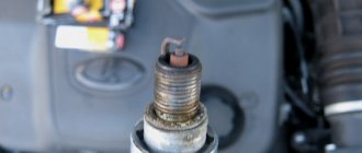
- 13/14 – coil and spark plugs, respectively;
- 15 – injector drivers;
- 16 – ignition contact group;
- 17 – detonation measurement sensor.
Grant instrument pinout - dashboard diagram
This part is the most difficult. The large number of pins and the miniature size of the terminals greatly complicates the search for the required group:
- 1/2 – connecting blocks for the front electrical harness;
- 3/4 – similar for the feed harness;
- 5 – lighting control unit;
- 6 – ignition switch module;
- 7 – on-board computer;
- 8 – lever for switching the position of the wipers;
- 9 – tidy;
- 10 – control of emergency modes;
- 11 – cargo compartment lid lock;
- 12 – diagnostic connector;
- 13 – block for the air intake drive;
- 14 – button to turn off the heated rear windshield;
- 15 – emergency contact;
- 16 – brake light switch;
- 17/18 – contact group – output to radio equipment (radio tape recorder);
- 19 – rotating equipment module;
- 20/41 – driver/passenger airbag drive;
- 21 – horn power supply;
- 22 – mounting block group;
- 24 – cigarette lighter group;
- 25 – backlight for stove control;
- 26 – interior lamp;
- 27 – contact group of the ignition switch;
- 28 – controller;
- 29 – incoming connector to the rear of the on-board network;
- 30 – electronic part of the gas pedal;
- 31 – additional resistor;
- 32 – stove motor;
- 33 – heater switch block;
- 34 – door lock module;
- 35/36 – cooling system head fan relay;
- 37 – compressor relay wiring;
- 38 – additional relay or reverse indication coil;
- 39 – air conditioner switch button;
- 40 – automatic transmission drive;
- 42 – evaporator thermometer;
- 43 – output to the rear wiring harness.
Possible malfunctions of the protection system and ways to eliminate them
If the ignition switch fails on a VAZ 2170, many motorists may confuse this problem with a breakdown of the ignition coil or, for example, the ignition module. But as for the 3Z specifically, its repair or replacement is carried out only if the key is not moved to position I or the steering wheel is not blocked after the key is removed. The key must always return to position I after starting the engine. If this does not happen, then you can either repair or replace the ignition switch.
Grant ECU pinout
The Lada Granta uses two types of electronic engine control units. Fundamentally, the systems differ slightly, which excludes the possibility of their interchangeability.
| Contact | 11183-1411020-51/52 | 11186-1411020-21/22 |
| A1 | DPKV | |
| A2 | Not involved | |
| A3 | Entering the first knock sensor | |
| A4 | Not used | |
| IN 1 | DPKV | |
| AT 2 | Not involved | |
| AT 3 | Input of the second knock sensor | |
| AT 4 | Main relay output | Not used |
| C1 | Empty | |
| C2 | DTV | |
| C3 | Mass air flow sensor | |
| C4 | UDC | |
| D1 | DDC weight | |
| D2 | Empty | |
| D3 | DTOZH | |
| D4 | Not applicable | |
| E1 | Zeroing the TPS | |
| E2 | Empty | CAN L |
| E3 | Empty | CAN H |
| E4 | Canister purge valve output | |
| F1 | Body from DTV | |
| F2 | Speedometer input | |
| F3 | Not applicable | DFM |
| F4/G4/H4/J4 | Output from injector No. 1/2/3/4 | |
| G1 | Antifreeze temperature sensor ground | |
| G2/G3 | Not used | |
| H1 | On-board electronics grounding | |
| H2 | UDC | |
| H3 | Not involved | Battery charge indicator output |
| J1 | Terminal No. 15 from the ignition switch | empty |
| J2 | Entrance No. 2 TPS | |
| J3 | DDC | |
| K1 | Supplying voltage to the TPS | |
| K2 | Entrance No. 1 TPS | |
| K3 | UDC | |
| K4 | DDK heater power connector | |
| L1/M1 | Leads to the ignition coil ¼ and 2/3 cylinders respectively | |
| L2/M2; L3/M3 | Not involved | |
| L4/M4 | Throttle actuator pin 5/6 | |
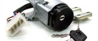
Design of ignition switches for all VAZ cars
Passenger cars of the “classic family” have been produced in Tolyatti since 1972. The ignition switch installed in these cars was inherited from the Fiat sedan, which was the prototype of the Kopeyka VAZ-2101. Below are diagrams, as well as wiring and photos of ignition switches installed in different LADA cars: from the “Classic” to the VAZ-2190 family. Special attention is paid to locks of the “2109” model, which were discontinued several years ago. All diagrams are borrowed without changes from reference books.
Grant relay diagram
Relay location in the main mounting block located in the engine compartment:
- 1 – drive of the cooler of the cooling system;
- 2 – central locking protection;
- 3 – secondary starter relay;
- 4 – additional part of the relay;
- 5 – turn signal and emergency signal breaker relay;
- 6 – wiper drive protection;
- 7/9 – insertion of high/low headlight modes;
- 8 – horn protection element;
- 10 – heated aft windshield;
- 11 – main relay block;
- 12 – fuel pump relay.
PRACTICAL CHECK
In response to our request, AVTOVAZ representatives responded that they were aware of the problem. And they assured that the locks meet all international requirements, and spontaneous blocking is caused by the human factor, that is, it happens through the fault of the drivers themselves.
We started our testing with tests on a special site. Having accelerated the car a little, we turned off the engine and took the key out of the lock to lock the steering wheel. While driving, they turned on the ignition, unlocked the steering wheel, engaged second gear and released the clutch to start the engine without turning the key to the “starter” position. No matter how much we turned the steering wheel on a flat surface and on uneven surfaces, we could not achieve spontaneous blocking. I had to disassemble the lock to look at the problem from the inside.
Detailed diagram of the VAZ Grant (dashboard)
The vehicle is supplied to the market with a 32-pin instrument panel as standard. The standard pinout of the Grant shield has only 26 pins involved. Residual connectors are provided for the possibility of adding equipment or custom modifications:
- 1 – to the low oil pressure sensor in the engine crankcase;
- 2 – to the handbrake indication switch;
- 3 – intended for service needs when diagnosing the instrument panel;
- 4 – to external lighting switches;
- 5/6 – similar for right and left turn signals, respectively;
- 7/8 – CAN L/H;
- 9 – indication of seat belt position;
- 10 – contact of the Reset button of the steering column lever;
- 11 – response of the brake fluid reservoir sensor;
- 12/13 – on the head optics, high/low beam position;
- 14/15 – foglight terminals front/rear, respectively;
- 16/18 – receiving immobilizer antenna signal;
- 17 – ground wire of the instrument panel;
- 19/21 – to terminal No. 30/15;
- 20 – for the drive of the electric power steering unit;
- 22 – for door closing sensors;
- 23/24 – MK buttons for forward and reverse, respectively;
- 25 – for an environmental thermometer;
- 26 – gas tank float indication.
Ignition switch VAZ 2110, 2111, 2112
The content of the article:
Checking the serviceability and diagram of the ignition switch for VAZ 2110, 2111, 2112
The ignition does not turn on on the VAZ 2110? One of the causes of the disease may be in the ignition switch. Don’t rush to replace the ignition switch with a new one, first try checking it yourself.
Malfunctions of the ignition switch VAZ 2110
To determine if the ignition switch is faulty, just check it. Install the key and check the resistance of the contacts with an ohmmeter when switching modes 1, 2, 3 with the key. If the ignition switch is working, then the resistance of the selected contacts should be equal to 0.
VAZ 2110 ignition switch diagram
Ignition switch pinout: 1. +12V is supplied for the sensor mic of the inserted key; 2. The mass arrives when the driver's door is open; 3. +12V goes to the starter (pin 50); 4. +12V goes out after turning on the ignition (pin 15); 5. +12V goes out when the key is inserted into pin 5 of the BSK; 6. +12V is supplied to illuminate the lock cylinder; 7. +12V comes from the battery (pin 30); 8. Not used.
Repair of ignition switch VAZ 2110
Just like that, for no reason, the ignition switch broke. The ignition turns on, but the starter does not turn and does not pump the pump. I started to disassemble the steering gear casing... I got to the lock and... I really wanted to invite the VAZ designer to visit... and ask him to unscrew his ignition switch mounting bolts (“special anti-theft bolts”) The bolts are hardened, with a smooth, even head. They did everything they could... they twisted it, made notches, the bolts did not budge... Apparently, no one had removed the lock since the car was manufactured (2005).
After many attempts to “culturally” remove the lock and see what happened to it, a decision was made, with the help of a sledgehammer and some kind of mother, to remove the lock as it turned out...
After several precise blows, the castle surrendered...
The cause of the lock breakdown was a popped-out ball of the steering wheel locking mechanism... During disassembly, it turned out that it was necessary to change the installation location of the steering column switches and the turn/light switch.
When I bought a new lock, I immediately bought and installed simple bolts under a shaped screwdriver... just in case.
Lada Granta: wiring diagram for rear wiring harness devices
The rear part of the car wiring is responsible for the equipment of the stern and sides of the car. all additional equipment is connected exclusively through this part of the highways:
- 1/2 – contact group for the dashboard;
- 3/4 – direction indicators;
- 5 – handbrake indicator;
- 6 – rear window heating contact;
- 7 – interior lamp;
- 8 – indicator of the driver’s seat belt position;
- 9 – cargo compartment illumination lamp;
- 10 – fuel pump drive;
- 11/15 – aft dimensions for the left and right sides;
- 12 – trunk lid lock drive;
- 13 – button for turning on the interior lamp;
- 14 – additional stop chain;
- 16-19 – door terminal blocks for the rear left, rear right, front left and front right doors;
- 20 – airbag control drive;
- 21 – contact group of license plate lights;
- 22 – on the dashboard;
- 23/24 – rear speed indicator sensors;
- 25/26 – seat belt pretensioners;
- 27 – group of dashboard contacts.
Where is terminal 30 located?
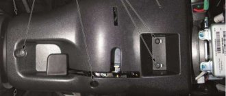
Here the side trim (2) in the driver's feet is unscrewed.
Arrows indicate mounting screws. Below it is a group of connectors (1). Under the side trim (1) on the passenger side next to the driver there is also a group of connectors (2). Arrows indicate mounting screws.
Right: The central switch unit (2) is located on the left under the instrument panel in the Audi A4. Above is the “13-place support for additional relays” (1).
Left: The illustration shows the placement of the central switch node sockets.
Standard terminal designations
The colorful mix of wires in a car is actually very well organized, since many parts of the car's electrical equipment are standardized. The numbers on various components and connecting elements of wires, as well as in electrical circuits on all German and some foreign cars have the same meaning:
Terminal 15 receives power only when the ignition is turned on from the ignition switch, while, along with the ignition/injection system, those consumers of electricity that should receive current only during operation of the vehicle are supplied with current. The wires to terminals 15 in most cases have a black sheath, sometimes with an additional colored stripe for certain current consumers.
Terminal 30 receives direct current from the battery positive or from the generator when the engine is running. If the tools are handled carelessly, this can lead to short circuits or cause sparks to rain if the wire connected to the battery negative is not removed. These wires, which are always live, are in most cases red, sometimes with additional colored stripes.
Terminal 49 refers to the intermittent and emergency light system.
Through terminal 53, voltage is supplied to the glass cleaning system.
From terminal 56, current is supplied to the low beam headlights through the yellow and yellow-black wires, as well as to the high beam headlights through the white and white-black wires.
Terminal 58 supplies power to the front parking lights, as well as the rear lights and license plate lights. The main color of the wire sheath is gray, sometimes with an additional colored stripe.
terminal 75 receives current when the ignition key is in the "On" position.
Terminal 31 is the ground terminal, through which the electrical consumer must be connected to ground in order to complete the electrical circuit. The corresponding wires have a brown sheath.
Labeled electrical connectors
In the Audi A4, individual wires are often bundled together in a black sheath, making it difficult to find a specific wire. In this case, orientation assistance is provided by multi-pin connections, which this chapter describes the exact number of wires and their exact location in electrical diagrams.
Terminal designation
Rate this post
Let's look at the main wires, or rather groups of wires, they are often called buses in electrical circuits, and they have standard symbols:
– Terminal “31” is the wires that are connected to the car body (ground)
– Terminal “50” is the wire, roughly speaking, that goes to the starter.
– Terminal “30” are wires on which +12 volts are always present, regardless of the position of the ignition switch, i.e. they are directly connected to the + (plus) terminal of the battery.
– Terminal “58a” supplies current to the front parking lights, rear lights and license plate lights.
– Terminal “75X” – on this bus +12 volts is present only in the “Ignition” position, but is absent at start, i.e. this is the case when +12 volts disappears from this bus in the “Starter” position
– Terminal “15a” is the wires on which +12 volts are present, in the “Ignition” position and the “Engine Start” position. The voltage from bus “15” powers the important parts of the engine, without which it will not start: spark plugs, ignition coil, various valves and the “brains” of the engine.
All of the above wires (except for ground “31”) go to the ignition switch.
Advice from experienced motorists and repairmen on the topic of where terminal 30 is located on the VAZ 2114 - you are welcome. All about renovation. Here we teach you how to repair a car yourself. How to repair a car yourself at home. We will help you with repairs and repair the car yourself. We know how to restore a car with minimal investment. I have attached video instructions.
Category: Car repair
Laughter on topic: It’s infuriating when you have to wake up your royal majesty at 6 a.m. on state affairs.
Published by Admin: at the request of Ilfat
Reviews from the car owner: Dad plays with his little daughter. Suddenly his daughter pushes him away and says: “Okay, that’s enough, I have a headache!” Dad looks at mom in bewilderment: “Is this what you’ve been taught since childhood, or what?”
Source
Preventive measures
In order for the factory wiring of the Lada Grant to serve for a long time and not break, experienced experts strongly recommend following a number of simple rules.
- Periodically check all contact connectors and terminals for oxidation and rust. Such damage to the connections can cause a short circuit and a critical decrease in the conductivity of the line, which is perceived by the on-board computer as an error or breakdown.
- Use only original consumables and electronic components. The use of counterfeit products does not guarantee the functionality of the circuit. At the same time, some elements, when damaged, cause a voltage drop in the network, which becomes a direct cause of failure of other equipment or a fire.
- Use special oil to treat contact groups. The fluid is sold in auto shops or electronics stores. After treatment, the contacts are covered with a moisture-impermeable layer, which increases their service life by 2-3 times.
- Carefully monitor the charge level and condition of the battery. The wiring of the Lada Granta critically perceives a significant voltage drop in the on-board circuits. As a result, this may cause damage to the firmware of electronic control units.
Standard ignition switch - article number, price, how it works, device
The module on Priora does not work directly with the components that initiate the engine start. For it to work properly, you need to wait a few seconds before starting until the fuel pump creates the required pressure. On the Priora, only wires are connected to it - the paths along which messages pass from the ignition switch to the electronic control unit.
The ECU of the Priora car just receives data about the position of the key and can crank the starter if this operation is “not blocked”. Due to a breakdown, it can only turn on the ignition, leaving the battery to work.
After the ECU key has turned, it gives commands to several parts at once. When you turn on the second position, let the fuel pump run for 5 seconds so that it pumps fuel from the tank closer to the engine.
When the starting process itself begins, the starter rotates - the force it creates goes to the crankshaft;
the ignition system element converts the low voltage current coming from the battery into a high one so that the spark plugs are “charged” and give a spark at the right moment;
The injector creates the first batch of air-fuel mixture to put it into the chamber, where everything is ready for it - the pistons “move”, the spark plugs spark.
In the module itself, everything is simple - there is a cylinder with a return spring inside, between the coils there is a locking ball that does not allow it to curl up more than necessary, and a locking rod holds the structure in place. Finally, as a complication of the entire system, there is an “immobilizer” - an anti-theft system that you can install yourself. It just takes a long time to set it up.
A regular kit with a master key and several door cylinders (with an immobilizer) costs from 1,800 - 2,000 rubles, catalog number - 2170-3704005. A set without a master key (without an immobilizer) can be purchased for 1,200 – 1,400 rubles, article number -2170-3704006.