Lada 2112 ᵀᴴᴱ ᴼᴿᴵᴳᴵᴺᴬᴸ › Logbook › WHY VAZ 2110-2112 DEVICES DO NOT WORK
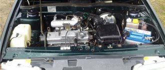
The instrument panel of the VAZ-2110-2112 contains: speedometer, tachometer, fuel level indicator, coolant temperature indicator, 12 different indicator lamps, 6 dashboard backlight lamps, one reserve socket for the indicator lamp and two wire connection blocks.
It is very easy to distinguish the pads, the one that is white in electrical diagrams is designated as X1, and the one that is red is designated as X2. The instrument panels themselves, installed on VAZ-2110 cars, can be of two types: the old model, where the instruments are placed symmetrically, and the new model, with fuel and coolant level indicators shifted to the right side of the dashboard. The biggest malfunction of the instrument panel will be its complete failure. In this case, neither the control lamps nor the devices themselves work. The driver, first of all, needs to check the 15 amp fuse F6. It is located in the mounting block. If it burns out, it is necessary to look for the cause of this phenomenon, otherwise the new one installed will repeat the fate of the previous one, that is, it will also burn out. The cause of blown fuses is a short circuit in the electrical circuit.
There are times when instrument needles begin to jump along their scales from minimum to maximum. Most likely, the reason for such actions of devices will be poor contact with ground. The ground wire coming from the instrument panel is attached to the partition separating the engine compartment from the passenger compartment. You can find it by removing the radio from the socket. But if an alarm was installed on your car, then it is quite possible that the fastening of this massive wire, for ease of operation, was moved to another place, more accessible. Usually, alarm installers move it behind the interior trim in the area where the driver’s left foot is located. A similar picture may occur when installing a radio. When connecting its negative wire, the ground wire of the instrument panel was unscrewed, and then it was wrapped poorly, as a result of which it weakened under the influence of vibrations transmitted to the car body. They wrap it poorly because it is not very convenient to do so.
If everything is in order with the fastening of the ground wire, then you will have to check the instrument panel itself. To do this, you need to pull it out as far as possible from its mounting location without disconnecting the wires going to the pads. You will need to check on the white block X1 the ground wire going to contact 1, and at the same time check the voltage on contacts 6, 9, 10, it should be equal to 12 volts. Look, on the back side of the instrument panel, for the integrity of the paths along which electric current flows to the corresponding consumers.
Another cause of instrument panel failure may be the cigarette lighter. The fact is that through this socket, some drivers connect additional devices, such as: a cell phone battery charger, an electric tire pump, or a car interior vacuum cleaner. Considering that these consumers require high current, either the cigarette lighter itself fails or fuse F19 blows, which leads to failure of the instrument panel. By the way, you can also disable the cigarette lighter by holding it in the on position for a long time. In these cases, you can make the instrument panel work by disconnecting the cigarette lighter connector if fuse F19 is intact.
In principle, the driver himself can eliminate all malfunctions associated with a complete failure of the instrument panel. For this, he does not need any additional knowledge in electrical engineering. The only thing he needs to know is the probable causes of failure of the instrument panel.
Source: www.drive2.ru
Featured Posts
Anatoly-
Car VAZ21124 Y7.2 tachometer does not work. What I did was check all the electrical circuits connected to the tachometer, throw in a new electronic unit. I changed the instrument panel, the tachometer does not work. I tried and tossed the EB. Bosh7.9.7 worked, I return Ya7.2 does not work. The guy says that the tachometer worked before. Who has any thoughts, what is the ambush?
Xander ROTTEN DICK
Open the ECU and ring 8 pins... no other thoughts.
romelo
Did you do something with her, or did he already arrive like this? You need to ring with a control or an oscilloscope, starting from the block; if there is no signal from the block, then it is already clear that the block. If repair is unrealistic, then you can somehow hook it up to the injectors or coil.
Softer
Car VAZ21124 Y7.2 tachometer does not work. What I did was check all the electrical circuits connected to the tachometer, throw in a new electronic unit. I changed the instrument panel, the tachometer does not work. I tried and tossed the EB. Bosh7.9.7 worked, I return Ya7.2 does not work. The guy says that the tachometer worked before. Who has any thoughts, what is the ambush?
The tachometer output is controlled by a key in the block to ground. And pulled up to +12V through a 4.7 kOhm resistor.
Check with a DIGITAL multimeter with the ignition on to see if there is pull-up voltage at the output.
Modified on July 3, 2010 by Softer
Anatoly-
I didn’t do anything with the block; the guy already arrived with one. The fact is that I bought a completely new EB from the store. I threw it in and the tachometer still doesn't work. I took the instrument panel from another car, it doesn’t work, I put the original instrument panel on another car, it works. And it works with BOSCH7.9.7. That is, there is no point in ringing the circuits inside the block. Maybe something is wrong with EEPROM? Or is it a bug?
andreikl
You might want to try attaching an external +12V resistor to the tachometer wire so as not to damage the unit. By the way, the tachometer wire can connect to 2 points on the tidy. Look where the tachometer wire went on the car from which the tidy worked
Softer
2 inputs - this is in old devices. Low voltage – the one for control units. And high-voltage - connected directly to the ignition coil.
masters41
Or maybe hang an external generator from the output of the unit to check the wiring and panel?
- 4 months later...
DGON-S
Check the battery charge, I had an increased charge of 15.5v. The tachometer turned off two seconds after starting.
The tachometer does not work on the VAZ 2110 injector reasons
REASONS FOR A NON-WORKING TACHOMETER
The tachometer in a car is used to indicate the number of revolutions of the engine crankshaft. Let's look at why the tachometer doesn't work and how to find and eliminate the cause of the breakdown. We will definitely dwell on the device and principle of operation, which will help to find out why the tachometer stopped working, the needle twitches or behaves inappropriately.
CLASSIFICATION BY OPERATING PRINCIPLE
- Mechanical or electromechanical tachometers with direct drive. The revolutions are transmitted to the dial indicator through a flexible shaft, which, through a worm gear, receives rotation directly from the crankshaft or one of the transmission shafts. The operating principle of the indicator is based on the phenomenon of eddy current induction. The operation and design of a magnetic tachometer are extremely similar to the operating principle of a car speedometer. In modern cars, a similar tachometer design is not used.
- Electric machine. A distinctive feature is the connection to a generator. It is used primarily on diesel engines, but for the purpose of unification, a device of this type can also be used on gasoline engines.
- Electronic. The signal can be taken either from the ignition system or directly from the computer. Installed on gasoline and diesel internal combustion engines.
DEVICE AND PRINCIPLE OF OPERATION
Main components of electric machine and electronic tachometers:
- measuring unit, or signal converter. It can be based on elements of analog circuitry or built using special microcircuits;
- display unit with analogue or digital display of the number of revolutions;
- auxiliary elements.
The operation of electronic tachometers is based on the conversion of individual signals or pulses captured from the computer, ignition system or generator into a signal “understandable” for the display unit.
CONNECTION DIAGRAM
When looking for the reason why the tachometer does not work, it is first of all important to understand the connection diagram and the type of signal. There are 3 typical connection schemes:
- to a contactless ignition system (the tachometer wire is connected to the primary circuit of the ignition coil). The operating principle is based on measuring the frequency of voltage surges in the primary circuit of the ignition system. Calculating the ignition angle is impossible without focusing on the number of crankshaft revolutions, therefore the sparking frequency directly depends on the crankshaft rotation speed. On 4-cylinder internal combustion engines, a full revolution of the crankshaft corresponds to 2 voltage pulses in the primary circuit. Accordingly, the higher the crankshaft rotation speed, the greater the frequency of voltage surges;
- connection to the contact ignition system. The operating principle and connection diagram are similar to the BSZ, but the design of the measuring unit will differ depending on the voltage of the input circuit;
- connection to the engine ECU. The principle of operation is still based on recording voltage pulses in the primary circuit of the ignition system, but the signal to the tachometer comes from the engine control unit;
- connection to the generator (the tachometer signal contact is connected to terminal W of the generator). The rotation of the generator pulley is carried out by a belt drive from the crankshaft, so the rotation speed of the generator rotor will always be proportional to the crankshaft speed. The change in the number of revolutions of the crankshaft can be calculated by constantly measuring the amount of EMF generated on the winding. By its operating principle, an electric machine tachometer resembles a conventional voltmeter.
SPECIFIC FAULTS
If the mechanical tachometer on a car stops working, there is mechanical damage to any of the structural elements. A broken cable of a flexible shaft, wear of the worm gear elements, the appearance of backlashes, deformations - all these reasons can cause the engine speed indicator to fail.
What to pay attention to if the electronic tachometer does not work:
- integrity of electrical wiring. In this case, it is important to check not only the signal wire, but also the ground and power supply of the instrument panel;
- quality of contacts. The presence of oxides and loose contact inside the chips may well cause the tachometer to fail;
- the integrity of the elements of the measuring unit, which are located behind the protective glass inside the dashboard. Among mechanical damage to transistors, burnout of microcircuits, tracks or swelling of resistors, the most common reason for a non-working tachometer is a violation of solder integrity. For example, on the Mitsubishi Padjero II, the appearance of microcracks in the soldering areas of the tachometer elements is a generally recognized disease.
What else is the reason for the speedometer not working?
However, often the reason for the speedometer malfunction lies elsewhere:
- Oil and dust get into the speed sensor, which is located in the engine compartment under the hood of the car.
The malfunction is eliminated after removing dirt and oil by washing the sensor. If the DS fails and needs to be replaced, any car owner can perform this simple operation independently.
The replacement sequence is as follows:
- place the machine on a flat horizontal surface;
- open the hood and find the speed sensor on the gearbox;
- by pressing the latch bracket, the plug is disconnected from the DS:
- to remove the sensor, use a 22 mm wrench, turning it counterclockwise;
- The new part is installed by screwing it in by hand. The use of a wrench is not recommended, as you may miscalculate the rotation and break the thread;
- install the connector, as evidenced by the click of the fixed part.
The driver should buy a new DS with similar markings. Otherwise, the speedometer needle will display incorrect readings.
- For some unknown reason, the VAZ 2110 speedometer stopped working. First of all, you need to check the most accessible elements associated with the speedometer. Since the car compartments are not ideally clean, dirt and moisture can damage any part, including wires and contacts.
Under the influence of moisture and dirt, wires and contacts can oxidize. Eliminating this cause is simple: the contacts must be removed, cleaned of oxidized deposits, wiped dry and reinstalled.
It is also necessary to check the integrity of the wires. Externally good wires may have broken sections of cores inside. Checking the serviceability of the wires involves ringing their surface with a tester.
During operation, the splines and elements that rotate the speedometer cable may be damaged. Such a defect may impair the operation of the instrument panel. You can verify its serviceability by testing it.
- The third, very important defect is the malfunction of the speed sensor. This device is located on the gearbox, adjacent to the exhaust manifold. This factor leads to heating and chafing of the DC wires.
The reasons for the sensor being out of working condition, the fault can be determined at the service center. The technician will perform this procedure in the presence of the car owner.
To troubleshoot the problem yourself, you should do the following:
- The speed sensor must be removed by unscrewing it from the gearbox;
- connect the DC wire to a screwdriver or drill, set the rotation counterclockwise;
- turn on the ignition.
The movement of the arrow indicates that the sensor is working properly. The weak link is most likely located in the vehicle's transmission. It is difficult for a driver without experience to cope with this task. In this case, the problem must be solved by car service specialists.
If the speedometer needle on a VAZ 2110 does not work, the speed sensor must be replaced.
The speedometer on a VAZ 2110 with an injector is an important element of any car, not excluding the “top ten”. VAZ 2110 drivers even with little experience can check and find the source of the malfunction of this device.
However, if you cannot determine the source of the speedometer problems, you need to draw the attention of technical service specialists to this problem.
VAZ tachometer connection diagram
The first car from the Zhiguli family equipped with a tachometer was the VAZ 2103. Neither 2101 nor 2102 had such a device. The tachometer is used to measure the crankshaft speed. It is a revolution counter, showing their number by deflecting the scale needle to a certain angle. The tachometer is also indispensable when setting up the carburetor - its indicators are taken into account when adjusting the idle speed and the quality of the fuel mixture.
Speed under control
Speed under control
It would seem, why do we need a tachometer? To safely travel around your native expanses, a speedometer is quite enough. If you also look at road signs from time to time, the speedometer will help you save money when meeting with law enforcement officers. The tachometer informs about something almost abstract: how many times the crankshaft manages to turn around in a minute. Why and who needs such information?
First of all, the driver of a car with a forced engine. It requires strict control of revolutions - here all the power is hidden in a narrow range of speeds in each gear, and the tachometer helps determine the moment of transition to the next gear - without dips or twists.
There is also an aesthetic side to the matter. People decorate their car as best they can, and a catchy dial on the dashboard is fashionable. Not everyone thinks about what is hidden behind the instrument readings. Is this why remote tachometers, which are plentiful in stores, are sometimes distinguished by an enviable - up to 25-30% - disregard for the accuracy of readings. We don’t recommend dealing with such people - fortunately, there are honest devices, which we’ll talk about.
In terms of price-quality ratio, the best tachometers are standard ones. Their work is based on different principles.
VAZ-2106 tachometer connection diagram
The “Sixes” were equipped with a tachometer model TX-193. This tachometer consists of:
- plastic cylindrical body with glass holder;
- a scale divided into zones of safe and dangerous modes;
- backlight lamps;
- a milliammeter with an arrow attached to its shaft;
- electronic printed circuit board.
The principle of its operation is based on measuring the number of electric current pulses in the primary (low-voltage) circuit of the car’s ignition system. In the VAZ 2106 engine, for one revolution of the distributor shaft, corresponding to two rotations of the crankshaft, the contacts in the breaker close and open exactly four times. These pulses are removed by the device from the final terminal of the primary winding of the ignition coil. Passing through the parts of the electronic board, their shape is converted from sinusoidal to rectangular, having a constant amplitude. From the board, the current flows to the winding of the milliammeter, where, depending on the pulse repetition rate, it increases or decreases. The arrow of the device reacts precisely to these changes. The greater the current, the more the arrow deviates to the right and vice versa.
Connecting a tachometer in carburetor VAZ 2106
Electric circuit of the speed counter of the carburetor “six”
In a contactless ignition system, the tachometer is connected not to the coil, but to the switch
Connecting a tachometer in injection VAZs
It should be taken into account that the colors of the wires and their purpose may differ depending on the manufacturer of the device, but for the standard “TX-193” device, which is usually used in “sixes”, the diagram is as follows:
- A white cable is required to connect the backlight.
- The red wire is connected to the ignition switch, a fuse is used for this, this cable supplies power when the ignition is activated.
- A white cable with a black break is required for connection to the car body.
- The brown wire connects to the K+ terminal on the coil.
- The black wire is connected to the charging current indicator relay. The latter, in turn, is installed on the right in the engine compartment.
- The gray-black cable is required to connect to the engine fluid pressure regulator installed to the left of the engine.
Instrument panel device
What to do if the tidy stops working? How to diagnose and repair the shield, how to disassemble the device correctly? To begin with, we recommend that you familiarize yourself with the features of the device.
This unit includes the following components:
- Tachometer or speed sensor. With its help, the control unit reads the number of crankshaft revolutions.
- Speedometer or speed sensor. Everyone knows what it is needed for - to demonstrate the speed of the car.
- , allowing you to determine the remaining displacement of gasoline in the gas tank.
- Antifreeze temperature sensor, which is also an internal combustion engine temperature controller. Thanks to it, the driver can know when the engine has warmed up to operating temperature and when the power unit is overheating.
- The device also includes indicators indicating whether electrical equipment is turned on or not working. A total of twelve indicator lights should be used.
- To enable the driver to use the instrument at night, the dashboard is equipped with backlight bulbs.
- The devices are equipped with an econometer - a fuel economy sensor that shows in which driving mode gas savings will be optimal. The same panels also use electrical circuit voltage sensors, according to which it is possible to detect the voltage level in the electrical network - undercharge or overdischarge.
- There is also an additional, backup connector in the device. Indicators of additional equipment that were not installed by the manufacturer are connected to it. For example, these could be airbags, fog lights, etc.
- On the back of the device there are connectors for connecting wiring.
To prevent you from confusing the pads during repairs or diagnostics, each of them is marked with a specific color.
For example, the red block, in accordance with the diagram, is marked as X2, and the white block is marked as X1. Domestic “Tens” can be equipped with different devices, in this case it all depends on the configuration and year of manufacture of the car.
The VAZ 2110 can use old or new devices:
- A distinctive feature of the old-style tidy is the installation of all sensors and indicators symmetrically.
- As for the new type of devices, the coolant temperature controllers, as well as the fuel level controllers, began to be located with a slight shift to the right. In addition, the new devices no longer use a voltage controller in the car network, as well as an econometer.
Connection diagram for tachometer VAZ-2108 and 2109
Let us immediately note that the fuel supply system – injector or carburetor – does not play a special role here. As you know, currently the most common are cars with the following engine types: gasoline or diesel. Depending on this, the tachometer is selected, unless, of course, it comes in the stock version. The thing is that on gasoline engines the tachometer reads data from the ignition coil, or rather, the impulses that arise here. However, the design of diesel power plants does not provide for this unit. Accordingly, here the tachometer reads pulses not from the ignition coil (for lack of one), but from the generator.
The first two wires (12-volt and Signal) are to contacts “B” and “K” of the ignition coil, respectively. All that remains is to secure the mass in any convenient place.
Removing the torpedo on the old model 2112
To completely remove the device from the car you will need:
- Turn off the on-board power supply.
- Remove the screws around the panel.
- Move the plastic cover of the shield aside and disconnect the wires from the buttons.
- Unscrew the panel fasteners.
- Then the device moves away from its seat and is disconnected from the on-board network.
VAZ-2110 tachometer connection diagram
- tachometer VAZ;
- trip computer;
- ECM;
- crankshaft position sensor;
- ignition module.
Tachometer VAZ 2110 - with four outputs: if it is on a car with injection, it is connected not to the ignition (input 2), but to the ECM controller with an additional output provided for this (input 1) - and in this case it reads the number of revolution pulses directly from the controller. It receives a signal about the position of the shaft.
Pioneer DEH-1500UB
pionrrr mvh-150ub gives an amplifier error amp error
Answers 1
Try turning off all the speakers, amplifiers, etc., leaving only the power and try turning it on, if it works, then connect one speaker at a time and look for where the short is.
Watch another video:
Sound amplifiers are needed in order to improve the quality of music playback by reducing its distortion when turning on high volumes. Sometimes car owners encounter amplifier errors on the Pioneer radio: the sound disappears in the speakers, and then the equipment starts working again, while the display shows “ERROR” DC." There are several ways to troubleshoot problems; you can choose the right one by determining the cause of the problem.
About the DPKV tachometer sensor
The tachometer has a sensor (crankshaft position sensor - DPKV). This device serves not only to count crankshaft revolutions, but also to determine its position at a certain moment, which is necessary for the electronic control unit to ensure proper operation of the power unit. When a metal object passes near the sensor core, an electrical impulse is generated in it, which is transmitted to the electronic engine control unit. The role of such an object in the power unit of a car is played by the crankshaft gear.
Symptoms
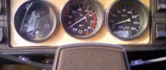
Any malfunction is preceded by the appearance of symptoms, minor problems or breakdowns. The tachometer was not spared similar signs. Symptoms of a tachometer malfunction are as follows:
- Poor operation of the instrument needle. It stops responding to an increase in speed, trembles, slowly decreases with a sharp decrease in speed, and gets stuck in a certain position.
- The dashboard stops working completely. The speedometer does not respond to changes in speed modes, the backlight does not turn on.
- The power unit loses power, speed stability, and stalls when shifting into gear or accelerating.
- High fuel consumption. The ECU cannot calculate the number of revolutions correctly. A speed sensor is involved in this calculation; failure of the tachometer system introduces a data error between all devices.
All the described symptoms appear as a result of the fact that the tachometer system for counting the revolutions of the power unit stops working smoothly. The following will describe how to check each element of the tachometer.
Why does the VAZ tachometer jump?
It often happens that the needle starts to twitch. If the car is fuel-injected, then troubleshooting involves connecting a diagnostic scanner and checking the engine systems. Jumps in the TX-193 needle in most cases are also a symptom of malfunctions associated with its electrical circuit. The reasons for this behavior of the device may be:
- lack of good contact at the negative terminal of the battery;
- oxidation or burning of the brown wire on the ignition coil;
- burning or wear of the contacts of the ignition distributor cap or slider;
- wear of the distributor shaft bearing;
- shorting the red wire powering the device to vehicle ground;
- malfunction of the crankshaft position sensor (for injection engines).
A similar problem is solved by stripping the contacts, replacing the ignition distributor cap, slider, support bearing, restoring the integrity of the insulation of the device’s supply wire, and replacing the crankshaft sensor.
Another jump may be due to the inoperability of the capacitor located at the bottom of the breaker. The capacitor may be broken or its contact is very weak.
What exactly needs to be done
Check the cap on each of the wires: if the copper is burnt, clean it with ASIDOL, ammonia and ordinary chalk. The taps on the module should also be cleaned. For better protection, you can apply lithium grease (Litol-24). Here's what you can't do:
- Check for the presence of a spark by bringing a “grounded conductor” to the tap;
- Connect the “+” terminal removed from the battery to ground with the engine running;
- Apply voltage “+12” to any of the module contacts.
How to perform an express check: the key is at “0”, then we measure the resistance between taps 2-3, 1-4. Both values must match. By the way, the multimeter must be a dial gauge.
If the tachometer on a VAZ does not work
Usually, the lack of response from the arrow is due to a broken contact in the connectors of the main wires of its connection, or damage to the wiring of the circuit. The first step is:
- Inspect the fastening of the conductor in brown insulation to terminal “K” on the ignition coil. If you detect poor contact, traces of oxidation, burning of a wire or terminal, fix the problem by cleaning the problem areas, treating them with anti-corrosion liquid, and tightening the fastening nut.
- Check the reliability of the connection of the black and white wire to the vehicle ground. If contact is broken, clean the wire and the surface to which it is attached.
- Using a tester, determine whether voltage is supplied to the red wire when the ignition is on. If there is no voltage, check the serviceability of fuse F-9, which is responsible for the integrity of the instrument panel circuit, as well as the condition of the ignition switch contacts.
- Disassemble the instrument panel and check the connections of the contacts in the tachometer wiring harness block. “Ring” all the wires going to the device with a tester.
Examination
It is better to test the component components of the engine speed counting system in order of priority. This will help to quickly identify the malfunction and conduct an additional examination of the condition of each element.
Before checking the electrical circuit and its parts, you should make sure that the fuel injection system is working. The serviceability of the gas distribution mechanism also affects the performance of the tachometer. Only after checking these components can we assume that the tachometer circuit is not working.
This device is located near the machine's generator pulley. You can check its operation using a multimeter. To do this you need:
- Set the multimeter to resistance measurement mode.
- Disconnect the sensor power supply connector.
- Connect the red control probe of the tester to terminal “1”.
- Connect the black measuring probe to terminal “2”.
- Crank the engine with the starter.
When open, the device will show a resistance of up to 550–750 Ohms. If the tester does not measure the operating resistance of the sensor, you will have to dismantle it. To do this, you will need to unscrew one nut that secures the element. Very often, metal shavings stick to the magnetic sensor and interfere with the opening. If chips have accumulated on the rod, they must be removed, the body must be cleaned with a solvent and the resistance measurement must be repeated.
After checking the DPKV, you need to check the integrity of the wiring that powers the sensor and transmits pulse signals to the control unit. It is necessary to inspect the wires and check the integrity of the insulation. You will also have to clean both halves of the connecting plug with solvent.
Ignition module
This device is most often prone to breakdowns. This happens due to a short circuit to ground. The check is carried out with the engine running. During operation of the power unit, it is necessary to remove the power wires from the spark plugs one by one. After this, you need to direct the end of each wire towards the engine block, but without touching it. A spark should appear from the end of each wire. It should be blue. If the spark is yellow or there is no spark at all, the module and wires will have to be ringed.
The wires can be tested with a multimeter only to check the integrity of the cores. It is not possible to determine an insulation breakdown in this way. It is better to replace all suspicious elements with new ones. Often, owners replace standard high-voltage wires with modern silicone analogues; this should not be done. The electrical resistance of such wires is very high; it does not allow the spark of the required discharge to pass through. It is also worth carefully inspecting the caps that are placed on the candles. Parts with poor contact or external defects must be replaced.
Classification by operating principle
- Mechanical or electromechanical tachometers with direct drive. The revolutions are transmitted to the dial indicator through a flexible shaft, which, through a worm gear, receives rotation directly from the crankshaft or one of the transmission shafts. The operating principle of the indicator is based on the phenomenon of eddy current induction. The operation and design of a magnetic tachometer are extremely similar to the operating principle of a car speedometer. In modern cars, a similar tachometer design is not used.
- Electric machine. A distinctive feature is the connection to a generator. It is used primarily on diesel engines, but for the purpose of unification, a device of this type can also be used on gasoline engines.
- Electronic. The signal can be taken either from the ignition system or directly from the computer. Installed on gasoline and diesel internal combustion engines.
Design and principle of operation
Main components of electric machine and electronic tachometers:
- measuring unit, or signal converter. It can be based on elements of analog circuitry or built using special microcircuits;
- display unit with analogue or digital display of the number of revolutions;
- auxiliary elements.
The operation of electronic tachometers is based on the conversion of individual signals or pulses captured from the computer, ignition system or generator into a signal “understandable” for the display unit.
Connection diagram
When looking for the reason why the tachometer does not work, it is first of all important to understand the connection diagram and the type of signal. There are 3 typical connection schemes:
- to a contactless ignition system (the tachometer wire is connected to the primary circuit of the ignition coil). The operating principle is based on measuring the frequency of voltage surges in the primary circuit of the ignition system. Calculating the ignition angle is impossible without focusing on the number of crankshaft revolutions, therefore the sparking frequency directly depends on the crankshaft rotation speed. On 4-cylinder internal combustion engines, a full revolution of the crankshaft corresponds to 2 voltage pulses in the primary circuit. Accordingly, the higher the crankshaft rotation speed, the greater the frequency of voltage surges;
- connection to the contact ignition system. The operating principle and connection diagram are similar to the BSZ, but the design of the measuring unit will differ depending on the voltage of the input circuit;
- connection to the engine ECU. The principle of operation is still based on recording voltage pulses in the primary circuit of the ignition system, but the signal to the tachometer comes from the engine control unit;
- connection to the generator (the tachometer signal contact is connected to terminal W of the generator). The rotation of the generator pulley is carried out by a belt drive from the crankshaft, so the rotation speed of the generator rotor will always be proportional to the crankshaft speed. The change in the number of revolutions of the crankshaft can be calculated by constantly measuring the amount of EMF generated on the winding. According to its principle of operation, an electric machine tachometer resembles a regular one class=”aligncenter” width=”448″ height=”412″[/img]
Typical faults
If the mechanical tachometer on a car stops working, there is mechanical damage to any of the structural elements. A broken cable of a flexible shaft, wear of the worm gear elements, the appearance of backlashes, deformations - all these reasons can cause the engine speed indicator to fail.
What to pay attention to if the electronic tachometer does not work:
- integrity of electrical wiring. In this case, it is important to check not only the signal wire, but also the ground and power supply of the instrument panel;
- quality of contacts. The presence of oxides and loose contact inside the chips may well cause the tachometer to fail;
- the integrity of the elements of the measuring unit, which are located behind the protective glass inside the dashboard. Among mechanical damage to transistors, burnout of microcircuits, tracks or swelling of resistors, the most common reason for a non-working tachometer is a violation of solder integrity. For example, on the Mitsubishi Padjero II, the appearance of microcracks in the soldering areas of the tachometer elements is a generally recognized disease.
Tuning
This is what often causes the dashboard to malfunction. Perhaps the new shield was not fixed correctly, which is why it actually does not work. Either when installing the wiring, not all cables were connected, or they were simply bent.
In such cases, only individual elements of the dashboard often stop functioning: for example, displays, battery, handbrake or oil pressure indicators, as well as the carburetor choke light. The instrument panel of the VAZ-2110 does not work after tuning - what to do in this case? The first thing to do is replace the wires.
Classification by operating principle
- Mechanical or electromechanical tachometers with direct drive. The revolutions are transmitted to the dial indicator through a flexible shaft, which, through a worm gear, receives rotation directly from the crankshaft or one of the transmission shafts. The operating principle of the indicator is based on the phenomenon of eddy current induction. The operation and design of a magnetic tachometer are extremely similar to the operating principle of a car speedometer. In modern cars, a similar tachometer design is not used.
- Electric machine. A distinctive feature is the connection to a generator. It is used primarily on diesel engines, but for the purpose of unification, a device of this type can also be used on gasoline engines.
- Electronic. The signal can be taken either from the ignition system or directly from the computer. Installed on gasoline and diesel internal combustion engines.
Design and principle of operation
Main components of electric machine and electronic tachometers:
- measuring unit, or signal converter. It can be based on elements of analog circuitry or built using special microcircuits;
- display unit with analogue or digital display of the number of revolutions;
- auxiliary elements.
The operation of electronic tachometers is based on the conversion of individual signals or pulses captured from the computer, ignition system or generator into a signal “understandable” for the display unit.
Connection diagram
When looking for the reason why the tachometer does not work, it is first of all important to understand the connection diagram and the type of signal. There are 3 typical connection schemes:
- to a contactless ignition system (the tachometer wire is connected to the primary circuit of the ignition coil). The operating principle is based on measuring the frequency of voltage surges in the primary circuit of the ignition system. Calculating the ignition angle is impossible without focusing on the number of crankshaft revolutions, therefore the sparking frequency directly depends on the crankshaft rotation speed. On 4-cylinder internal combustion engines, a full revolution of the crankshaft corresponds to 2 voltage pulses in the primary circuit. Accordingly, the higher the crankshaft rotation speed, the greater the frequency of voltage surges;
- connection to the contact ignition system. The operating principle and connection diagram are similar to the BSZ, but the design of the measuring unit will differ depending on the voltage of the input circuit;
- connection to the engine ECU. The principle of operation is still based on recording voltage pulses in the primary circuit of the ignition system, but the signal to the tachometer comes from the engine control unit;
- connection to the generator (the tachometer signal contact is connected to terminal W of the generator). The rotation of the generator pulley is carried out by a belt drive from the crankshaft, so the rotation speed of the generator rotor will always be proportional to the crankshaft speed. The change in the number of revolutions of the crankshaft can be calculated by constantly measuring the amount of EMF generated on the winding. According to its principle of operation, an electric machine tachometer resembles a regular one class=”aligncenter” width=”448″ height=”412″[/img]
Typical faults
If the mechanical tachometer on a car stops working, there is mechanical damage to any of the structural elements. A broken cable of a flexible shaft, wear of the worm gear elements, the appearance of backlashes, deformations - all these reasons can cause the engine speed indicator to fail.
What to pay attention to if the electronic tachometer does not work:
- integrity of electrical wiring. In this case, it is important to check not only the signal wire, but also the ground and power supply of the instrument panel;
- quality of contacts. The presence of oxides and loose contact inside the chips may well cause the tachometer to fail;
- the integrity of the elements of the measuring unit, which are located behind the protective glass inside the dashboard. Among mechanical damage to transistors, burnout of microcircuits, tracks or swelling of resistors, the most common reason for a non-working tachometer is a violation of solder integrity. For example, on the Mitsubishi Padjero II, the appearance of microcracks in the soldering areas of the tachometer elements is a generally recognized disease.
On vehicles with an alternator connection, a non-functioning tachometer may indicate a faulty alternator. In this case, the breakdown is accompanied by the lighting of the low battery charge indicator and the sporadic lighting of a “garland” of warning lights on the dashboard.
In some types of design, changes in the linear resistance of high-voltage wires can make adjustments to the accuracy of the engine speed indication.
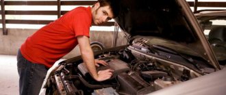
How to find the cause of the problem yourself
In addition to a visual inspection, for DIY diagnostics you will need a universal measuring device. If you know how to use a multimeter, you can easily check the power supply, ground, and also test the signal wire for a break.
The power supply is checked in DC measurement mode, the measurement range is up to 20 V. “Minus” is constant, “plus” appears only after the ignition is turned on. Pulses on the signal wire should appear when the crankshaft rotates. To search for a break, the multimeter must be switched to resistance measurement mode - ohmmeter. Sometimes, to detect a bad contact, it is enough to move the connector or harness in which the signal wire of the speed indicator is laid.
Tachometer needle twitches
The problem of a twitching needle is best known to owners of the GAZ 3110 Volga. The problem occurs on cars manufactured before September 1999 and equipped with instrument cluster 38.3801 (JSC Avtopribor). Due to design defects, the natural operation of a car generator, in which the amount of charging current is regulated by an alternating voltage supply to the excitation winding, leads to the twitching of the needle.
The tachometer needle may twitch due to weakened tension of the alternator belt, but in most cases it is possible to repair the tachometer on the Volga by replacing the dashboard and modifying the connection diagram.
Source: autolirika.ru
General faults
During use, did you notice that the needle in the car’s speedometer is inactive (at any speed)?
The first thing you need to do is check the tightness of the fastening nut of the speedometer tips, as well as its drive.
speedometer tip nuts
If, after checking, no comments were found or the work performed did not bring the desired effect, in other words, there is a risk of damage to the speed indicator drive or breakage of the flexible shaft.
In the latter case, the part will have to be changed. In this case, do not forget to apply a good-quality lubricant to the area near the seal (Litol-24 may be suitable for these purposes).
Once the work is completed, push the shaft through the seal - this will help distribute the lubricant over the surface of the cable.
The occurrence of a knocking noise while driving may indicate a malfunction of the speedometer flexible shaft.
The reasons for this phenomenon include huge bends in the cable under the device panel, dents, etc. Make sure that the radii of the roundings do not exceed 10 cm.
From time to time while driving you can see a “growling” sound, approximately in the front part of the car. The reason may be the speedometer cable, which often makes noise in the absence of regular lubrication.
This is one of the more important car devices. Its task is to demonstrate the number of revolutions of the engine crankshaft at a certain point in time.
A tachometer breakdown is not that critical. But in the long term, it may become a prerequisite for engine malfunction and new costs for the car owner.
Speedometer not working properly
Because how can you cope with a breakdown, and what could be the main reasons for a breakdown?
In fact, there are not so few of them. In the case of an electric tachometer, in most cases the LED screen of the device fails. Repairing in this case is problematic - it is better to change the screen.
Nissan Qashqai tachometer contacts.
Nissan Qashqai tachometer contacts
Malfunctions of the tachometer are often caused by a decrease in the properties of the contacts or faulty wiring (in this case, impulses from the motor to the device may not arrive at all).
To eliminate such problems, you need to carefully examine all the wires for cracks and breaks. If you find a crack, simply solder it, and if a break is detected, replace part of the wiring.
The cause of a malfunction of the tachometer may be a failure of the engine speed sensor.
engine speed sensor
It is not difficult to diagnose the problem - the tachometer needle begins to “jump” in different directions. The only way to bring the tachometer back to “life” is by replacing this element.
speed sensor
Please note that the above malfunctions and methods for eliminating them are of a general nature. Each car model may have its own aspects, and we will talk about some of them in more detail.
Messages 10
1 Topic by spy46 2013-06-13 12:08:50
- spy46
- New member
- Inactive
- From: Kursk
- Registration: 2013-04-11
- Messages: 32 Thanks : 2
- Car: VAZ 21102 1.5i 1999
Topic: Resolved: Tachometer needle twitches or shows nothing
Tell me where to look for something, I have a VAZ 2110 injector, 1999. The tachometer either doesn’t show at all, or the needle twitches somehow, where to look and check what, in the tidy I checked all the contacts and cleaned it up, it didn’t help
2 Reply from Admin 2013-06-13 12:31:44
- Admin
- Administrator
- Inactive
- Registration: 2012-02-20
- Messages: 3,257 Thanks : 624
Re: Resolved: The tachometer needle twitches or shows nothing
spy46 , tachometer readings are taken from the ECU. Could there be a bad contact on the ECU connector? If there is a BC, then look at the readings on it; there may be a problem in the instrument cluster itself. Do another tidy test, what happens?
3 Reply from spy46 2013-06-13 12:55:49
- spy46
- New member
- Inactive
- From: Kursk
- Registration: 2013-04-11
- Messages: 32 Thanks : 2
- Car: VAZ 21102 1.5i 1999
Re: Resolved: The tachometer needle twitches or shows nothing
The tidy test doesn't work for me((
4 Reply from spy46 2013-06-14 11:45:54
- spy46
- New member
- Inactive
- From: Kursk
- Registration: 2013-04-11
- Messages: 32 Thanks : 2
- Car: VAZ 21102 1.5i 1999
Re: Resolved: The tachometer needle twitches or shows nothing
after all, it looks like there’s something in the tidy, BC shows
5 Reply from Admin 2013-06-14 12:11:25
- Admin
- Administrator
- Inactive
- Registration: 2012-02-20
- Messages: 3,257 Thanks : 624
Re: Resolved: The tachometer needle twitches or shows nothing
spy46 , that means there is a reason to buy a new, tuning one!
6 Reply from iliaBkmz 2013-06-14 17:01:57
- iliaBkmz
- Forum legend
- Inactive
- Registration: 2012-11-12
- Posts: 2,038 Thanks : 584
- Car: outlander and 2104
Re: Resolved: The tachometer needle twitches or shows nothing
The tidy test doesn't work for me((
What type of device do you have? VDO or AP?
7 Reply from spy46 2013-06-17 10:26:34 (2013-06-17 10:28:13 edited by spy46)
- spy46
- New member
- Inactive
- From: Kursk
- Registration: 2013-04-11
- Messages: 32 Thanks : 2
- Car: VAZ 21102 1.5i 1999
Re: Resolved: The tachometer needle twitches or shows nothing
what's the difference between them, I only know they come with LCD displays
Schematic electrical diagrams, connecting devices and pinouts of connectors