Car tuning has now become quite common; it is used to improve the technical parameters of the car and to stand out from the crowd of cars of the same type. The installation of air intakes, wings, additional lighting is used; in more complex cases, elements of the interior, control electronics and engine are changed. All this together is tuning... Car tuning is not the prerogative of only modern or imported cars; below we will look at what can be done with the engine of a regular and ordinary VAZ-2110, if you have the desire, a little money and straight hands.
5d211cb36a4837081cdc09bd1c930436.jpg
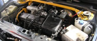
Increasing the power of a car engine requires increasing the air supply; a standard air filter cannot cope with this task. Therefore, instead we install a low-resistance air filter, for example from Pro-Sport, its cost will be about 2 thousand rubles.
Replacing the filter allows you to get about 8% increase in engine power. Of course, it's not just about one filter, but it is necessary to get maximum efficiency from all other components. Increasing the air flow to the carburetor will be one of the elements that will increase engine power
511.jpg
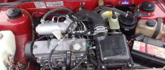
By adjusting the size of the intake pipes, we change the distribution of maximum torque across engine speeds. Increasing the length of the pipes increases torque at low speeds, and if you shorten the pipes, the torque increases at medium and high speeds.
If you use a sports receiver, for example, or Torg-Mash, the engine accelerates to maximum speed.
Installing an intake receiver will also require some fine work in the future to adjust the valve timing; this can be done in a garage, but it will require certain qualifications.
Replacing the camshaft
One of the most difficult operations in tuning a VAZ-2110 engine is replacing the camshaft. It is this that determines the time and duration of opening of the intake and exhaust valves and affects the amount of power and torque of the engine. Quite a lot of modernized camshafts are sold for engine tuning; the price per set will be about 10 thousand rubles.
Replacing the camshaft is also associated with the need to synchronize the operation of the engine's intake and exhaust camshafts. You can use a split pulley, also called a Vernier pulley. This pulley model allows you to configure the intake camshaft to operate either advanced or retarded.
If the camshaft is advanced, then at the overlap point the intake valve will be more open than the exhaust valve. And in the case of retardation, everything will be the other way around; at the point of overlap, the intake exhaust valve will be open more than the intake valve. This allows you to adjust the operation of the camshaft and obtain some operating parameters.
If the camshaft is advanced, this will shift the maximum power output slightly downward to lower engine speeds. Delaying the operation will shift the maximum power to higher speeds.
The very question of setting up and establishing the operation of the engine timing mechanism is quite complex and it is advisable to entrust it to an experienced mechanic. You can read more about how to replace the shaft in this article.
Modification of the VAZ 2110, 2111, 2112 engine
This modification will be useful in almost the entire line of VAZ injection engines, regardless of the type and composition of the ECM equipment and the ignition system in particular.
0:329
Just a word of caution - based on the results of comments and questions. ! Intervening and making changes to the electrical circuit of a car requires at least basic skills in electrical engineering and awareness of the actions being performed! If you feel that electrical circuits and car electrics are a little out of your profile, contact a more qualified person or an experienced auto electrician. This is in your own interests. And it will save you from unpredictable consequences.
0:1174
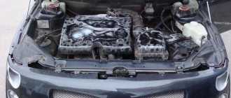
In order. Engine VAZ 21124. 1.6 liters, 16 valves. Individual ignition coils (or dual module with high-voltage wires). Everything is beautiful. And at first glance, it seems that everything is thought out, so it should work clearly and reliably. It turns out that this is far from true. This is a VAZ!
0:1706
1:2211
Customized ignition coils
1:65
Quite a lot has been written about ignition problems on this engine - about the choice of spark plugs, replacement and selection of individual ignition coils (hereinafter - IKZ).
So I came face to face with this problem.
The main manifestations are that the engine rotates unevenly at idle (speeds dance in the range of approximately 720-840 rpm), sluggish acceleration with twitching, increased consumption. In principle, most people understand that misfires are rare, but they do happen. The ECU doesn't see them directly. Last year, one coil clearly started to fail - the ECU saw it. I replaced it and it started to loosen up a bit. But still the engine was missing something. What a good spark! Here's more about this. From versions: 1:1256
· replacing spark plugs (the current NGK ones lasted only 7 tons km) with something more expensive from the “platinum, iridium” series, etc. is an expensive option.
1:1497
· changing IKZ, and they are a little over 7 years old (the original ones are BOSHevsky, mileage is 75 tkm) is a little expensive (the cost of one IKZ is around 540 UAH ($22), and there are four of them) and there is no confidence that the problem will go away.
1:1836
· Mass air flow sensor, which is also not fun...
1:1889
· look into the ECU to check the serviceability of keys, current-limiting resistors, etc.
1:2050
Acting at random or based on assumptions is not my method or my approach. Reading the ECU showed: 1. Speed jumps 2. Injection time jumps, slightly 3. Reduction ratio jumps at idle (9-15 degrees) - a bit too much 4. Power supply, mass air flow sensor, TPS - everything is stable and beautiful. 5. ECU masses - everything is ideal (previous modifications and correct wiring were made) Verdict - unstable sparking.
The ICP parameters were measured - the resistance of the primary winding, inductance, the resistance of the secondary winding (taking into account the diode in the high-voltage circuit), checking for the absence of short-circuited turns - the norm. The coils have a minimal (± 2%) spread and nothing alarming in the parameters. More on this later. On a hastily assembled “stand” there is a normal spark, a little weaker in appearance than on a classic with a contactless ignition system, but still clear throughout the entire range of rotational speeds (2 - 45 Hz), with an accumulation time of 2.0 ms. The coils are live. The rubber caps in the explosive part of the coil have been replaced. To complete the picture, I decided to look at the diagrams on the coils with an oscilloscope on the engine, pulled out my C1-65A - a reliable, proven workhorse to the machine and off I went. The ignition is on. The engine is running. On board the network (to the battery) 14.35V, which at idle, one hundred at 2000 rpm is stable. Amazing! Let's see. As usual, I start with power to the coils (+12V from the ignition switch) and I’m HORROR! On the coils, as well as on the IKZ harness connector, the ripple is exactly 2.5V. I was not mistaken, I measured it in 2 modes (and the oscilloscope has been an everyday tool for many years and not the only working tool - there is no room for doubt). I apologize for the bad photos - the scan is slow and the shutter speed in the camera is short.
1:2970
2:504
2V/division Ripple range almost 2.5V
2:576
3:1081
0.5 V/Division with DC cutoff. The photo is not entirely successful, but the presence of almost 2.5V in scope is visible!
3:1291
Clear, beautiful needle-like dips in the ICD accumulation phase with a duration of about 2 ms and a peak-to-peak of 2.5 V!
There are practically no ripples visible on the battery (slightly small, about 50-80mV). That's it, we've arrived.
The cause has been localized. There's no point in looking any further for now. That's where the dog is buried! A little calculation in Excel and I get a reduction in the maximum current (accumulation) at the moment of rupture by 18%, which is equivalent to a reduction in the energy accumulated in the coil and transferred by the coil to the spark plug by 33.6%!
Impressive?
(the dependence of the accumulated energy on the current strength is quadratic W=(L*I^2)/2 - this is for reference!) That’s why there are a lot of articles on the pains of selecting candles, IKZ. I’m already silent about those who have high-resistance silicone wires from the external ignition module. As usual, everything is banal and in the AvtoVAZ style - wiring, contacts, connectors. Well, the conservative and indifferent “engineering thought” has touched here... Take action! Step one.
Required. General diagram of the ECM and its required fragment.
3:3039
4:504
Fig. 1 ECM diagram 21124 (January 7.2, Bosch 7.9.7)
4:575
5:1080
Fig.2 Installation of capacitors in the IKZ harness
5:1157
Since there is a powerful pulsed inductive load (ignition coil) and a long power circuit to it (IKZ harness, engine compartment harness to the ECU), the dips need to be smoothed out by installing capacitors, and as close as possible to the load itself. Which was done immediately.
5:1634
I will disappoint the skeptics - this approach is a classic technique in the circuit design of power pulse devices. No shamanism, miracles or anything else UnReal. In short, this approach can be called “compensation of the internal resistance of the power supply for a pulsed inductive load”
5:2182
2 capacitors (Photo 1, 2) - twisted the leads, soldered the wires, insulated the leads with heat shrink and then completely heat-shrink the entire structure again, only the wires stick out from the outside into the IKZ harness between 2-3 cylinders (cut the electrical tape, (corrugation and so on with a cut ) we see a twist - 5 blue wires. And to it (twist-crimp S1 (Fig. 1, 2)) we connect 2 capacitors of 2200 μF * 25V (105°C). An alternative and more technologically advanced option is to avoid touching the well-packaged twist - strip the lead (thick) blue wire coming from the ECM connector in a circle by 5-8mm and solder the positive wire of the capacitors to it. The negative wire is led out with a separate wire to the ground point under the M6 bolt on the cylinder head (next to the oil pressure sensor). Use a lot of high-voltage windings of coils for connecting capacitors is highly undesirable
.
5:1473
Capacitors: 2200 µF 25V 2 pcs. They are also suitable for higher voltages 35/50/63V, but not 16V. Capacitance range 3000 - 4700 µF. There is no need to exceed the upper limit either! Manufacturers: Jamicon (TX, TL, TZ, WG, TK, TM), Samwha (WB, WF, WL, RD), CapXon (KF, LZ, KM, GL), etc. in order of my preference. 105 degree, low impedance (LowESR).
2 capacitors of 2200 µF will be more efficient and durable than one of 4700 µF. Take my word for it, I don’t want to bog you down with theory.
5:2232
6:504
Photo 1. Blank
6:538
Don't mix up the polarity!
The stripe on the body indicates “MINUS.” An error with the polarity when connecting will lead to a short circuit, swelling and boiling of the capacitor, and problems with the wiring.
6:897
7:1402
Photo 2. Next, we insulate the leads and the entire workpiece with heat shrink
7:1521
This is how everything looks already assembled; the engine cover does not interfere.
7:1655
8:2160
Photo 3. IKZ harness and additional capacitors
8:87
9:592
Photo 4. Connecting the masses in the area of the pressure sensor on the cylinder head
9:699
Result: the ripple range decreased to 0.8V - which is 3 times. The pulses at the switched terminals of the coils (overshoot, swing, duration, oscillatory process) are almost identical, which pleases and confirms the presence of stable sparking. Before adding capacitors, characteristic emissions were observed, indicating the absence of a discharge in the spark plug. The car actually drove more lively, as it was before - the acceleration dynamics returned, the dips disappeared, and there was a clear and accurate response to the gas pedal.
Consumption immediately decreased by about 0.7-0.9 liters (7.8 instead of 8.5 or more in the city). At XX stable speed. It starts up much faster
(the starter's cranking time is exactly 2 times shorter).
And this is all on the same candles and coils! For the purity of the experiment, I screwed in the “old” candles, which had a fair amount of wear on them. The picture has not changed. The engine runs smoothly. 9:2248
Step two. Extremely necessary.
9:62
Looking at the electrical circuits of the ECM 2110 (21124) (Fig. 1), I saw that the coils are powered directly from the ignition switch. Despite the fact that the ECU has its own direct power wire (about 2.5 - 4 mm kV) with the battery, it also powers the fuel pump, injectors and everything else. The power supply circuit for the coils is made with a wire of sufficient cross-section (about 2.5 mm2 exactly), in the IKZ harness, in the engine compartment harness to the ECU and EVERYTHING! Further to the ignition switch from the ECU harness, the wire is visually thinner. Naturally, over time, wear of the contact group of the ignition switch, an increase in the resistance of the connector contacts (due to oxidation and weakening of the spring properties) - the result is in all its glory in motion and on the oscilloscope screen. To put it simply, the chain to the coils consists of 4 connectors, the contact group of the lock, which is especially susceptible to wear.
9:1472
10:1977
Rice. 3 Connecting the IKZ to the main relay of the ECM
10:2058
11:504
Twist S5
11:525
Therefore, it was decided: to take power to the IKZ from the main relay of the ECU, and it is powered directly, by a separate wire (about 6 mm kV) from the battery. The power circuit and electromagnetic (or electronic) power relay are just right here. Which is what was done. In fact, it was long overdue! I don’t see any point in installing a separate relay yet. It will simply duplicate the main relay of the ECU, which is not very loaded. I cut off the blue wire from the “S5” crimp (Fig. 1, 3) and soldered it to the pink-black ECU extending from the main relay. The length is enough. The S5 crimp is located in the branch of the ECM harness towards the connector to the dashboard or IMMO - it is not difficult to find, just track the thick blue wire for powering the coils in the common harness in the branching area. Bite it off the twist and pull it out (release it) towards the engine shield. I recommend replacing the fuse (position No. 33 in the diagram) in the used circuit from 7.5A to 10A
11:2086
The result of the final stage is that the pulsations on the IKZ decreased to 0.35V, i.e.
2 more times. Result: ripples (dips) at the beginning – 2.5V; after adding filter capacitors - 0.8V; after reconnecting the IKZ power supply to the main relay of the ECU - 0.35V The result is clear - stable idle speed and dynamics without any complaints.
11:575
Price: 2 capacitors, heat shrink, electrical tape. And just a little time and desire.
11:741
Go ahead. Injectors. The picture is much better. There is less ripple, but it is also there - there are less currents in this circuit. And a 1500uF*25V capacitor was installed there a month earlier. Also to the harness, in heat shrink, minus the M6 bolt on the cylinder head. The purpose of the installation is to suppress interference during the operation of injectors in the on-board network and on additional equipment. Injection time and other engine operating parameters have not changed, and in fact should not have changed. The cooling fan controller was connected to the same injector power circuit. Quite a convenient connection point. The power wire and temperature sensor are nearby.
11:1810
I really understand that capacitors, even those designed for 105°C in the cylinder head area, will have a hard time. But, after looking at the Samwha and Jamicon datasheets, I wasn’t very upset. At 105°C, the declared resource is no less than 3000-5000 hours (for some LowESR series). In principle, not a little. Time will show. The main thing is that the problem is localized, investigated, and eliminated. Solutions are outlined.
11:2429
https://www.drive2.ru/b/2173392/
11:35 next article:
Replacing the alternator belt without power steering VAZ 2112
Replacing an alternator belt without power steering in a VAZ 2112 I was driving a couple of days ago for no reason, a whistle coming from under the hood, it stopped
12:860
Rating 2.93 [7 vote(s)]
33907
Chip tuning
Control of the ignition process, intake and exhaust, etc. This is a task for the engine control unit. In a standard engine, the unit is designed to obtain optimal power and fuel consumption. If we have replaced all or at least part of the elements described above, then setting up the control unit is simply necessary.
This will allow you to tune the engine to the changed parameters and get maximum power from it. Chip tuning can be carried out in car service centers where there is the necessary equipment and specialists.
So we briefly got acquainted with the tuning of the VAZ-2110 engine. As can be seen from all of the above, this will require some financial costs, but as a result you can get a significant increase in engine power to 120-140 hp. Especially if you carry out additional grinding and joining of joints for the block head, as well as manifolds and pipes.
Another detailed article on tuning a VAZ engine
Gasoline supply
I think there is no need to explain the importance of maintaining a stable, constant gasoline pressure in the injector rail:
- During normal city driving, the standard fuel regulator is sufficient at high speeds, but a situation arises that with the injectors constantly open, it leads to a general decrease in pressure in the rail
- As a result, the fuel supply decreases, poor atomization results, and engine malfunction
- Therefore, boosting the engine requires increasing the pressure by 0.5 - 1 atmosphere, it all depends on the degree of boosting the engine
- Naturally, it will be necessary to adjust the injection program to ensure the correct mixture composition
- Today, in the latest (so-called “transitional”) models, as well as new 1.6-liter engines, a drainless system is used; the RTD is located in the tank with the fuel pump assembly and creates a higher pressure of 3.8 Atmospheres
Injectors
A natural process when, when boosting the engine, a situation often arises that the performance (amount of fuel supplied) is simply not enough:
- In this case, you will need to replace the nozzles, install more efficient ones, or install a second row of nozzles
- Option two is quite difficult and time-consuming, and it is not always possible to implement it even in a standard block.
- Therefore, it is easier to install more efficient injectors, having a productivity from +15% to +50% (and it is undesirable to use publicly available injectors used on GAZ cars; apart from high productivity, they have no more advantages)
- The disadvantages are the speed and non-linear characteristic at the beginning of its range, where a regular car has XX
- In addition, as a rule, 4-2-1 “spiders” are installed on souped-up cars, which work well in a wide speed range
- Spiders of the 4-1 system did not take root in civilian tuning due to the narrow range of their effective operation
- And the principle of operation of the exhaust is based on the vacuum created in front of the closed exhaust valve, this contributes to improved purging of the cylinder
The most important thing when carrying out tuning is a professional approach, in addition, care when performing all operations. Because not every driver understands all the intricacies of engine operation, so it is better to entrust the tuning of the car to experienced professionals. Since this will protect you from inevitable mistakes typical for beginners during tuning, it will help save time and money. Additionally, watch a video on the tuning you are interested in.