Either two brake light bulbs (in both headlights) or one (in one headlight) may not light up at once. Let's look at the causes of this very common malfunction on VAZ 2108, 21081, 21083, 2109, 21091, 21093, 21099 cars.
1. Check the fuse.
No. 6 for mounting block 17.3722, F3 for 2114. If it burns out, replace it with a new one. Subsequently, it will be necessary to find out the reason for the blown fuse, perhaps a small short circuit somewhere.
2. The contacts in the brake light lamp holders have oxidized.
Rotate the lamp in the socket several times to knock off the oxidized layer. To enhance the effect, you can remove the bulbs and clean the contacts with sandpaper.
3. The brake light bulbs in the headlight have burned out.
In appearance, the lamp may appear to be in good working order. Two lamps can burn out at once. Therefore, we replace the non-burning paw with a known good one and see if it burns or does not burn.
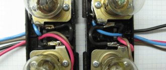
4. The contacts in the wiring block, which is placed on the terminals of the tracks on the headlight circuit board, have oxidized.
We remove and put on the block several times or clean the contacts on the board and in the block.
5. The tracks in the headlight circuit board are burnt out.
We take out the board and visually inspect the tracks. Burnt out ones can be restored by soldering wires to them.
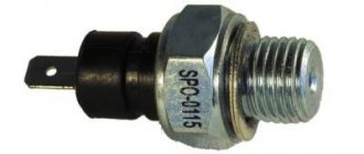
5. The brake light sensor is faulty.
It is located under the brake pedal. We remove two wires from it - white and red and connect them together with a piece of wire. The brake lights are on fire - we change the sensor, no, then we check the electrical circuits.
6. The electrical circuit of the brake lights is faulty.
It is necessary to identify an oxidized contact, a burnt-out wiring or a burnt-out connection in the mounting block. To do this quickly and efficiently, you need to know the electrical diagram for connecting brake lights.
Plus the brake lights come from output 30 of the generator to block Ш8 (the far left one in the engine compartment, pink wires) to the mounting block. Then through the fuse (No. 6, F3) in the block to block Ш4 inside the passenger compartment to the white wire going to the brake light sensor. That is, current is supplied to the sensor through the white wire. Next, from the sensor along the red wire to block Ш2 (second from the right inside the cabin) and through the mounting block to block Ш9 (the large transverse one in the cabin) to the red wire running through the entire cabin to the block of the rear left, and then the rear right headlight.
Minus - black wires coming out of the blocks to the headlights.
You can check the presence of current in the circuit elements using a test lamp - connecting one end to the terminals and the other end to ground. Or by supplying current with a separate wire from the battery positive to the elements of the electrical circuit.
Read more about finding a “break” in electrical circuits: “How to find a break in a car’s electrical wiring.”
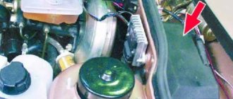
The fuse box on the VAZ-2109 is located under the hood and looks like this:
We also attach a diagram of the location of fuses and relays in the block :
Fuse mounting block 2114-3722010-60
K1 - Headlight wiper relay, K2 - Turn signal and hazard warning relay, K3 - Windshield wiper relay, K4 - Brake light and parking light relay, K5 - Power window relay, K6 - Horn relay , K7 - Heated rear window relay, K8 - High beam relay, K9 - Low beam relay, F1 - F16 - Fuses, F1 - F20 - Spare fuses
Fuse mounting block 2114-3722010-18
K1-relay for turning on headlight cleaners; K2-relay-breaker for direction indicators and hazard warning lights; K3 - windshield wiper relay; K4-relay for monitoring the health of lamps; K5-power window relay; K6 - relay for turning on sound signals; K7-relay for turning on the electric heating of the rear window; K8-relay for high beam headlights; K9-relay for low beam headlights; F1-F16 - fuses
Fuse mounting block 17.3722
1 — relay for turning on headlight cleaners (K6); 2 — rear window washer time relay (K1); 3 — relay-interrupter for direction indicators and hazard warning lights (K2); 4 — windshield wiper relay (KZ); 5 — contact jumpers in place of the relay for monitoring the health of the lamps; 6 — relay for turning on the heated rear window (K10); 7 - spare fuse; 8 — headlight high beam relay (K5); 9 — relay for low beam headlights (K11); 10 - fuse; 11 — relay for switching on the electric motor of the engine cooling system fan (K9); 12 - horn relay (K8)
leon1193 › Blog › Decoding the fuse box VAZ 2109-2114
Decoding the fuse block VAZ 2109 F9 (7.5 A)
Right fog light and fog light warning lamp
F8 (7.5 A
) Left fog light fuse
F1 (10 A)
Headlight wiper motors (at the moment of switching on), headlight wiper switch relay (contacts) and headlight washer switch valve
F7 (30 A)
Electric motors headlight cleaners (in operating mode).
Relay for turning on headlight wipers (winding). Electric motor for heater fan, washer pump, rear window wiper. Rear window washer timing relay. Rear window washer activation valve. Relay for the electric radiator cooling fan (winding) and for turning on the rear window heating. Indicator lamp for turning on the heated rear window and glove compartment lighting F16 (15 A)
Turn indicators, relay-breaker for turn indicators and hazard warning lights (in turn indicator mode).
Indicator lamp for turning on the turn signal. Rear lights (high-speed running lights). Windshield wiper motor and relay. Generator excitation winding (when starting the engine) and brake fluid level warning lamp F16 (15 A)
Fuse VAZ 2109 warning lamps: emergency oil pressure, closing the carburetor air damper, turning on the handbrake.
“STOP” display. Coolant temperature and fuel level indicators. Indicator lamp for reserve fuel remaining. Voltmeter. “CHECK ENGINE” indicator light. “TEST” board. Warning lamps for the on-board monitoring system, seat belts not fastened and doors not closed. Power circuit for inertial door lock switch F3 (10 A)
Rear lights (brake signal lamps).
Interior lighting F6 (30 A)
Electric window motor, power window relay
F10 (7.5 A)
License plate lights.
Engine compartment lamp. Instrument lighting lamps. Indicator lamp for turning on the side light. Heater lever illumination display. Cigarette lighter lamp Left headlight (side light). Left rear light - side light F5 (20 A)
Radiator cooling fan electric motor and its activation relay (contacts).
Sound signal and relay for its activation F11 (7.5 A)
Right headlight (side light).
Right rear light (side light) F2 (10 A)
Direction indicators, relay-breaker for direction indicators and hazard warning lights (in hazard warning mode).
Hazard warning light F4 (20 A)
Rear window heating element.
Relay for turning on the heated rear window (contacts). Socket for connecting a portable lamp. Cigarette lighter F15 (7.5 A)
Right headlight (high beam)
F14 (7.5 A)
Left headlight (high beam).
Indicator lamp for high beam headlights F13 (7.5 A)
Left headlight (low beam)
F12 (7.5 A)
Right headlight (low beam)
1 (8 A)
Reserve fuse in the VAZ 2109 block
2 (8 A)
Reserve
3 (8 A)
Electric motors of headlight wipers at the moment of switching on).
Relay for turning on headlight wipers (contacts). Headlight washer activation valve 4 (16 A)
Headlight wiper motors (in operating mode).
Relay for turning on headlight wipers (winding). Heater fan motor. Electric motors for the rear window washer and wiper pump. Rear window washer timing relay. Valve for turning on the windshield and rear window washer. Relay for the electric radiator cooling fan (winding) and for turning on the rear window heating. Indicator lamp for turning on the heated rear window and glove compartment lighting 5 (8 A)
Turn indicators, relay-breaker for turn indicators and hazard warning lights (in turn indicator mode).
Indicator lamp for turning on the turn signal. Rear lights (high-speed running lights). Windshield wiper motor and relay. Generator excitation winding (when starting the engine). Brake fluid level warning lamp. Indicator lamp for emergency oil pressure. Indicator lamp for covering the carburetor air damper. Indicator lamp for turning on the hand brake. “STOP” display. Coolant temperature gauge. Fuel level indicator. Indicator lamp for reserve fuel remaining. Voltmeter 6 (8 A)
Fuse for rear lights (brake signal lamps) in block 2109. Interior lighting
7 (8 A)
License plate lights.
Engine compartment lamp. Instrument lighting lamps. Indicator lamp for external lighting. Heater lever illumination display. Cigarette lighter lamp 8 (16 A)
Radiator cooling fan electric motor and its activation relay (contacts).
Sound signal and relay for its activation 9 (8 A)
Left headlight (side light).
Left rear light (side light) 10 (8 A)
Right headlight (side light).
Right rear light (side light) 11 (8 A)
Direction indicators, hazard warning relay-breaker (in hazard warning mode).
Hazard warning light 12 (16 A)
Rear window heating element.
Relay for turning on the heated rear window (contacts). Cartridge for connecting a portable lamp. Cigarette lighter 13 (8 A)
Right headlight (high beam)
14 (8 A)
Left headlight (high beam).
Indicator lamp for high beam headlights 15 (8 A)
Left headlight (low beam)
16 (8 A)
Right headlight (low beam)
Mounting block VAZ-2113, 2114, 2115. Location of fuses and relays.
New model mounting block VAZ-2113, 2114, 2115. Location of fuses and relays.
Relay Description:
K1–relay for turning on headlight cleaners; K2–relay-interrupter for direction indicators and hazard warning lights; K3 – windshield wiper relay; K4 – lamp health monitoring relay; K5 – power window relay; K6 – relay for turning on sound signals; K7 – rear window heating relay; K8 – headlight high beam relay; K9 – relay for turning on low beam headlights; F1–F20—fuses; X11 – terminals of the wiring harness block
Table of circuits protected by fuses on the VAZ 2114
Fuse number
Circuits protected by a fuse
Rear fog lamp switching relay. Rear fog lamp lamps. Rear fog lamp switching indicator
Direction indicators, relay-interrupter of direction indicators and hazard warning lights (in hazard warning mode) Hazard warning lamp
Front interior lamp. Central interior lamp. Luggage compartment lighting. Illumination lamp for the ignition switch. Lamp for monitoring the engine management system. Brake light bulbs. Trip computer (if installed)
Socket for connecting a portable lamp. Relay for turning on the heated rear window (contacts). Rear window heating element
Sound signal. Horn relay. Cooling fan electric motor. Fan fuse.
Direction indicators, relay-interrupter for direction indicators and hazard warning lights (in turn indication mode). Reversing lamps. Relay for monitoring the health of lamps. On-board control system display unit. Instrument cluster. Insufficient oil pressure indicator lamp. Parking brake indicator lamp (brake light fuse). Brake fluid level indicator lamp. Low battery indicator lamp. Trip computer (if installed). Generator excitation winding (in engine starting mode). Front windshield wiper. Seat heating control.
Numbering of plugs in the connecting blocks of the VAZ 2113, 2114, 2115 mounting block
Diagram of the VAZ-2113, 2114, 2115 mounting block Option No. 1.
Relay Description:
K1–relay for turning on headlight cleaners; K2–relay-interrupter for direction indicators and hazard warning lights; K3 – windshield wiper relay; K4 – lamp health monitoring relay; K5 – power window relay; K6 – relay for turning on sound signals; K7 – rear window heating relay; K8 – headlight high beam relay; K9 – relay for turning on low beam headlights;
Diagram of the VAZ-2113, 2114, 2115 mounting block Option No. 2.
Pinout of connectors of the VAZ-2113, 2114, 2115 mounting block.
Complete set of mounting blocks VAZ-2113, 2114, 2115.
Date added: 07/14/2014
Author: Dmitriev Alexander
- Electrical equipment
- Engine
- Brake system
- Other
- Steering
- Transmission
- Suspension
- Tuning
- VAZ 2110
- Other
- Engine
- Steering
- Electrical equipment
- Transmission
- Brake system
- Suspension
- Tuning
- VAZ 2114
- Electrical equipment
- Engine
- Brake system
- Other
- Steering
- Transmission
- Suspension
- Tuning
- Lada Priora
- Steering
- Engine
- Suspension
- Electrical equipment
- Tuning
- Brake system
- Transmission
- Video publications
- VAZ tuning photo stream
- Operation and repair manuals
Possible malfunctions: signs and causes
If the feet do not burn, the reason may be the following:
- bad contacts;
- damage to the wiring located in the corrugation between the door and the body;
- burnt out lighting elements.
There is a situation when the brake lights are constantly on if the side lights are on. In this case, the headlights may not light up. If they are turned off, additional lighting fixtures operate normally.
- the contacts of the parking lights and stop lights have been short-circuited;
- there is no weight on the dimensions;
- the two-pin lamp is faulty;
- the circuit closed, but did not open.
If the parking lights and brake lights are on and the ignition is turned off, then you need to check whether the lampshades are shorted to the housing. The reason may be poor contact of the negative wire with ground.
The purpose of each of the fuses on the car
If you turn over the removed cover, then on its inside you will see a diagram of the location of the relays and fuses in the mounting block (fuse block). On it, all these elements are numbered and designated from F1 to F20. Naturally, everyone is responsible for the performance of various consumers in the vehicle’s electrical network:
Diagram with the location of fuses VAZ 2114
- F1 – rear fog light and indicator lamp for turning on the latter (10 A);
- F2 – turn signal breaker relay, VAZ 2114 emergency alarm, turn signals (10 A);
- F3 – front and central interior lighting, trunk, trip computer and brake light bulbs (7.5 A);
- F4 – heated rear window (20 A);
- F5 – sound signal, cooling system fan (20 A);
- F6 – power windows (30 A);
- F7 – electric motor for heater, front window, washer, glove compartment lamp, cigarette lighter (30 A);
- F8, F9 – fog lights, right and left, respectively (7.5 A);
- F10, F11 – left clearance, as well as right, indicator for turning on dimensions, license plate lighting, as well as instrument lighting lamp, ashtrays (7.5 A);
- F12, F13 – right and left low beam, respectively (7.5 A);
- F14, F15 – high beam left and right, respectively (7.5 A);
- F16 – turn signals, dashboard indicators – parking brake, low battery, etc., as well as a trip computer (15 A);
- F17-20 – reserve respectively for 7.5, 10, 30 and 20 A.
The VAZ 2114 fuse diagram also contains backup fuses for 7.5, 10, 20, and 30 A, located in the lower part of the VAZ 2114 fuse block. Having pulled out the supposedly blown one, you should inspect it visually. If it is clear that the integrity of the thread is broken, then it can be unequivocally stated that the reason for the inoperability of the vehicle equipment lies precisely in the malfunction of the fuses. You can replace the inoperative one with a backup one of the same power according to the data that is presented to you by the diagram on the back of the plastic cover of the mounting block.
How to properly replace a burnt out element
Removing the fuse box
You need to pull the fuses out of the corresponding sockets using special plastic tweezers, which can be found here, in the upper right corner of the VAZ 2114 mounting block. You cannot pry fuses on non-energized circuits with any metal objects due to the risk of a short circuit. It should be taken into account that the electrical circuits of the sound signal, alarm, etc. are always energized. To ensure safety when repairing the circuits, the circuit must be de-energized - you just need to disconnect the wire from the “negative” terminal.
It is not always possible to visually accurately determine the performance of fuses. It will be possible to make a clear decision only after the “ringing”. To do this, you will need a regular tester, which will need to be set in advance to the “dialing” mode. After this, it will be enough to simply attach two terminals of the tester to the terminals of the suspicious fuses. If a characteristic sound is heard, the fuse is good - the cause of the malfunction of the car’s equipment is not in it, but probably somewhere further in the wiring or in the device itself.
Lastly, never use copper “inserts” or fuses that are not rated for amperage. Using an inadequate replacement designed for a higher current, there is a risk of damage to the “track” of the unit’s printed circuit board and even failure of the electrical appliance. Insufficiently powerful fuses will not be able to ensure long-term and uninterrupted operation of the current consumer in the vehicle's electrical network.
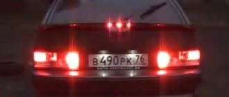
Replacing a stop repeater with your own hands
If repairing the repeater is not practical, it should be replaced.
The replacement process consists of the following steps:
- Using a wrench, unscrew the fastenings of the rear part of the stop and remove it.
- Then we connect the positive wire of the lighting fixture to the terminal where the brake light frog is located. To do this, you need to run the wire into the luggage compartment, unscrew the trim on the right side, and connect it to the desired terminal. The disadvantage may be a bolt in the luggage compartment.
- Heat shrink should be applied to the wiring. To prevent the wires from dangling, they need to be secured with insulating tape.
- The final step is to check the device for functionality.
Photo gallery
If a repeater with incandescent lamps is installed on the car, then when connecting a device with LEDs according to the above diagram, the lamp control will not work correctly due to different loads. In this case, you should insert the positive wire into the light bulb control unit and connect it to terminal 54H.
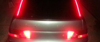
As a brake light, a strip with LEDs can be glued to the upper part along the entire length of the rear window. It needs to be connected to a standard device, and it will work in the same way. It is important to maintain polarity. To make the tape less conspicuous, it can be painted black. Attach the tape using double-sided tape. We check for functionality.
