Greetings
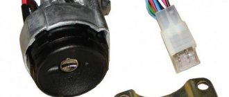
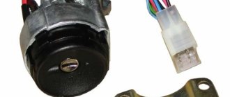
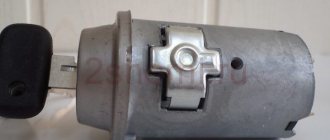
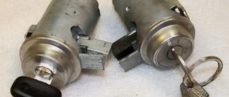
The Nine lacks a rather important function for me - the ability to listen to music without turning on the ignition, while allowing the radio to turn itself off when the key is removed. I decided to fix this problem by installing a new ignition switch from a VAZ 2110 with illumination of the cylinder, starter protection, and a key sensor. (lock 2110 of the new model differs from the old one in better illumination and a tighter return spring). Also, the replacement was prompted by the non-working steering wheel lock and the lack of a second key for my lock.
And so, let's get started: I bought an ignition switch 2110 from REKARDO FORTEX, according to the seller, it’s quite popular (I’d like to believe it), with the help of a chisel and a hammer I unscrewed the breakaway bolts of the old lock, armed myself with two circuits, had a free evening, a soldering iron and a good mood, and began to create. We have two schemes:
Pinout of the new VAZ-2109 ignition switch (injector high panel):
1. comes +12V constantly 2. comes +12V constantly 3. comes +12V after turning on the ignition (pin 15), does not disappear at start II; 4. +12V arrives after turning on the ignition (contact 15/2), disappears at start (II); 5.position I, +12V goes to the starter (pin 50); 6. +12V arrives after turning on the ignition (pin 15), does not disappear when starting II; 7. +12V comes from the battery (pin 30); 8. +12V comes constantly.
Pinout of the ignition switch VAZ-2110:
1. comes +12V for the sensor mic of the inserted key; 2. the mass arrives when the driver's door is open; 3. +12V goes to the starter (pin 50); 4. +12V goes out after turning on the ignition (pin 15); 5. +12V goes out when the key is inserted to pin 5 of the BSK; 6. +12V is supplied to illuminate the lock cylinder; 7. +12V comes from the battery (pin 30); 8.not used.
To start the car and set it in motion, the first thing we must do is place the key in the ignition, thereby starting the engine. Also, with the help of this device we can shut down the engine and control the electronics modes.
The ignition switch is the starting mechanism of electrical equipment that supplies voltage to the electrical circuit. The starter spins the engine using the flywheel, a large disc with teeth located between the clutch and the engine. During starting, the teeth of the starter and flywheel are brought into mesh position. At this time, the engine rotates according to a control signal from this lock using battery power.
During operation, the ignition switch supplies current from the battery to the starter traction relay. This is an important part, without which the machine will not fulfill its purpose. In addition to power control, the ignition switch prevents battery discharge in a quiet state. The engine starts from the starter by turning the key.
Types of the castle
Let's take a closer look at what ignition switches are. The following types of locks are found on the VAZ-2109 car:
- New sample. The lock has three positions and a short key.
- Old style. The lock has four positions, a long key and an ignition relay, the fourth position is for the parking light.
The key is removed in one position with the system turned off. In the first position the radio is turned on. In the second operating position, all electrical consumers are started. At the starting location, one starter is turned on, and the power supply to the system that consumes power is turned off. When the engine is running, the key returns to the second position. When at rest without a key in the lock, in the zero position, only lighting devices and alarms can continue to operate.
Thus, having studied the ignition switch diagram for the VAZ-2109, it should be noted that the lock consists of mechanics and electrics, where contact wires are located that supply current and thus start the car.
The device provided for such an operation - the ignition switch - helps start most cars and drive further. It is equipped with both foreign-made cars and products of the domestic automobile industry, in particular, our “nines”. Breakdown or malfunction of this element will create difficulties for the driver to start the engine.
Starter circuit for VAZ 2110, 2111, 2112
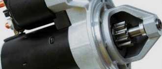
Starters of type 57.3708 were installed on VAZ-2110 cars and had the following technical characteristics:
- Rated power 1.55 kW
- Current consumption at maximum power no more than 375 Amperes
- Current consumption in the inhibited state is no more than 700 Amperes
- Current consumption in idle mode no more than 80 Amperes
The connection diagram for the starter for the ten is shown above, here is its explanation:
- battery
- generator
- the starter itself
- egnition lock
| 1 – drive shaft; | 20 – contact bolts; |
| 2 – front cover bushing; | 21 – output of “positive” brushes; |
| 3 – restrictive ring; | 22 – bracket; |
| 4 – gear with the inner ring of the overrunning clutch; | 23 – brush holder; |
| 5 – overrunning clutch roller; | 24 – “positive” brush; |
| 6 – drive shaft support with liner; | 25 – armature shaft; |
| 7 – planetary gear axis; | 26 – tie rod; |
| 8 – gasket; | 27 – back cover with bushing; |
| 9 – lever bracket; | 28 – collector; |
| 10 – drive lever; | 29 – body; |
| 11 – front cover; | 30 – permanent magnet; |
| 12 – relay anchor; | 31 – armature core; |
| 13 – holding winding; | 32 – armature shaft support with liner; |
| 14 – retractor winding; | 33 – planetary gear; |
| 15 – traction relay; | 34 – central (drive) gear; |
| 16 – traction relay rod; | 35 – carrier; |
| 17 – traction relay core; | 36 – gear with internal teeth; |
| 18 – contact plate; | 37 – layering ring; |
| 19 – traction relay cover; | 38 – hub with the outer ring of the overrunning clutch. |
Variety of locks for VAZ 2109
Having abandoned the left-hand drive position as in the “classics”, the designers took care of a comfortable right-hand place for using the key in their first front-wheel drive cars. This added ergonomics to the cabin. To perform its function, the main element used to start the car is equipped with two components:
- mechanical;
- electric.
The first block is responsible for fixing the steering wheel while the key is removed. The second block contains the pinout of the VAZ-2109 ignition switch, which is entrusted with the mission of supplying voltage to consumer electrical appliances.
The developers have provided for the presence of certain electrical devices in the ninth Lada model, which are capable of operating regardless of the state of the ignition unit. These include:
- car flashing emergency lights;
- “stops” of rear lights;
- dimensional optics;
- interior lighting;
- instrument panel light bulbs.
It must be taken into account that the VAZ-2109 ignition switch circuit is adjusted to its direct variety. Two types of locks can be installed in the “nines”:
- late model, which has three positions, does not use a relay and is activated with a short key;
- an early example that has four detent positions, a built-in relay and a long key.
Typically, drivers can easily visually determine the type of system installed. You can navigate by the working length of the key .
Pinout of lock VAZ-2113, VAZ-2114, VAZ-2115
Pinout of the ignition switch VAZ-2113, 2114, 2115:
- comes +12V for the microphone of the sensor of the inserted key;
- the mass comes when the driver's door is open;
- +12V goes to the starter (pin 50);
- +12V goes out after turning on the ignition (pin 15);
- +12V goes out when the key is inserted to pin 5 of the BSK;
- comes +12V to illuminate the lock cylinder;
- +12V comes from the battery (pin 30);
- not used.
Scheme of VAZ and car ignition switch
The structure of a car ignition switch
- Locking rod
- Frame
- Roller
- Contact disc
- Contact sleeve
- Block
- Protrusion of the contact part.
The lock mechanism is connected to many wires. They continue from the battery, connecting all the electrical devices of the car into a single chain. When you turn the ignition key, the electrical circuit is closed from the “-” terminal of the battery to the ignition coil. As a result, the current passes through the wires to the ignition switch, through its contacts it is directed to the induction coil, after which it returns back to the “+” terminal. As electricity passes through the coil, it generates high voltage, which it transmits to the spark plug. Therefore, the key closes the contacts of the ignition circuit, thereby starting the car engine.
Power-up modes used
At each of the turns, the connection of certain devices is provided. There are markings in a circle in front of the socket indicating the position to which a certain mode corresponds.
Null
To activate this mode, just insert the key into the “secret”. In this case, devices that are directly connected to the battery remain active.
Additional consumers will be put into operation after the larva is rotated at a certain angle. Voltage is supplied to pins 30/1 and 30.
The first is “ignition”
In the first position, the driver can turn on the front lighting, such as the low and high headlights. The tidy and interior light up responsively. The connection diagram for the VAZ-2109 ignition switch is activated during this turn, releasing current to the 30–INT pair.
When there is a connection between terminals 30/1 and 15/1, the rear lights, reversing lights, turn signals are operational, and the generator excitation winding is energized. The XX solenoid valve also receives power.
In this position, contacts 30/1 and 15/2 are closed, which ensures the operation of, in addition to the head light optics, the functioning of the fog lights, the rear window wiper and its heating. The headlight cleaners, heater fan and engine cooling system propeller are connected to this contact.
The second is the “starter”
By moving the key to the current position, the driver does not block the connection of electrical consumers that were started in the previous “ignition” position. This fully applies to both the closed contacts of the pair 30/1 - 15/1, and to the pair 30 - INT.
The main change that the VAZ-2109 ignition switch connection diagram provides in such a situation is the activation of a pair of contacts 30–50. This allows the starter to start.
It is important to know that the key is not held in the “starter” position on its own, but springs back to the previous position automatically as soon as the driver releases the force.
Third – “parking”
At this angle of rotation, consumers started in the “ignition” position and closed contacts 30 – INT remain activated. A closed pair 30/1 - P is also added. It is responsible for the parking lighting.
Testing the serviceability
The lock's service life is limited. After it fails, it is necessary to repair or completely replace the product. The functionality is checked after inserting the key into the “secret”.
Failures occur due to mechanical wear or loss of contact. The check is carried out by turning the key. If it begins to jam, then as a temporary solution it is possible to use silicone grease by dripping it inside.
In order for the wiring diagram to function correctly, you need to know which contacts to connect to each other. Typically the following wiring system is used:
- red connects to the cable from the starter;
- the pink wire goes to “+” from the 12 V battery;
- brown +12 V is used to start the ignition relay;
- white – relay on;
- black and blue connect other consumers.
It is necessary to check the contacts for the presence of carbon deposits or the possibility of oxidation. Burning contacts can be heard in the cabin by the characteristic smell of burnt insulation.
Voltage is supplied to the electrical power circuits of consumers of the electrical equipment of the VAZ 21093 car through the ignition switch (lock).
Let's consider the order of connecting the wires to the ignition switch, the pinout of the ignition switch terminals and the purpose of each wire (to which circuit it supplies voltage).
For current unloading of the ignition switch contacts, an ignition relay 113.4737-10 is included in its circuit, which is mounted next to it under the instrument panel.
Wires of the ignition switch of a VAZ 21093 car - connection order, pinout of contacts
Ignition key position: “O” (off)
The lock contacts “30” (pink wire – “plus” from the generator) and “30/1” (brown wire – “plus” from the generator) are energized. No electric current flows into the system.
Key position: “I” (ignition)
Contacts “30” (pink wire) and INT (black wire) are closed. Voltage is supplied through one black wire to the exterior lighting switch, instrument lighting switch, through the other to the steering column switch for briefly turning on the high beam headlights.
Contacts “30/1” (brown “positive” wire) and 15/1 (white wire) are closed. Voltage is supplied to the generator excitation winding, the ignition system, to the windshield wiper, carburetor solenoid valve control unit, turn indicators, reversing lamps, and control devices.
Contacts “30” (pink “positive” wire) and “15/2” (blue wire) are closed. The low and high beam headlights, fog lights, headlight cleaners, rear window cleaner, heated rear window, washer, heater fan, and engine cooling fan on the radiator are turned on.
Key position “II” (starter)
Contacts “30” (pink wire) and “50” (red wire to the starter) are closed.
In addition, “30” and “INT” remain closed, as well as 30/1 (brown wire) and “15/1” (white wire on the ignition relay).
Key position “III” (parking)
“30” and “INT”, “30/1” and “P” are closed (on VAZ 2108, 2109, 21099 cars this contact was used to turn on the parking light, the wire is yellow).
Notes and additions
The following are not powered through the ignition switch: emergency, sound, light alarms, interior lighting, dimensions, brake lights. security alarm. electric door locks (if equipped).
For the VAZ 2109, as well as for all other cars, the ignition switch is one of the most basic elements of electrical equipment. This element consists of a mechanical and electrical part. The mechanical part is responsible for locking the steering wheel when there is no key in the lock, and the electrical part is responsible for supplying voltage to the necessary electrical circuits depending on the selected position.
Design and principle of operation of the lock assembly
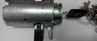
On a VAZ 2109 car, 2 standard modifications of the lock can be installed. The old one has catalog number 21080-3704005-60. It features four key positions (long), and also contains an ignition relay. The new unit with catalog number 21080-3704005-30 has only three key positions and does not have a relay.
To connect all the wires to the VAZ 2109 car lock, a contact group is used. Each of the key positions has its own blocking, and therefore consumer groups.
Contacts “30” and “30/1” are closed. All dependent power circuits are disabled.
In this position, voltage is supplied to the elements of the ignition control system. To do this, the white and brown wires are connected, and the pink wire is connected to black and blue. In this case, several groups of contacts are formed. For example, “30 INT” turns on the power supply circuit for external lighting, including high beam lighting, and the dashboard lighting. Contacts “30/1” and “15/1” provide voltage to the direction indicator lamps, reverse lights, elements of the ignition system, etc. The pair “30/1”, “15/2” powers the low/high beam headlights, fog lights , washer, fans.
Read also: Ball joints are replaced in pairs or one
The ignition relay, which was switched on in the previous step, continues to operate. The main one is a pair of contacts “30”, “50”, which provides voltage for the starter to operate. In parallel to it, circuits should be formed from contact connections “30/1”, “15/1”, as well as “30/1”, “15/2”. The consumers that are connected in this case are similar to those described for position “I”. The pink wire in the contact pair, together with the black one, is shorted to red (instead of blue).
Used to supply voltage to the components of the parking (“30/1 P”) and side lighting/dashboard lighting (“30 INT”) components. The black wire forms a closed circuit with the brown and pink wires.
The lock and its circuit perform two functions: electrical and mechanical. The essence of the first is to close certain groups of contacts based on the position of the key. From a mechanical point of view, when the ignition is turned off, the steering wheel is blocked, making it impossible to rotate. That is, the second function is protective.
Types of ignition switches for VAZ 2109.
The ignition switch, as already mentioned, is a very important element in any car. Almost all equipment in a car operates through the ignition switch. What is the exception? Regardless of the ignition switch, only the rear license plate illumination, side lights, brake lights, hazard warning lights, instrument panel illumination and interior lighting function in the Nine.
At the same time, the ignition switch itself on VAZ 2109 cars can be different: a new model - with three positions, a short key and without an ignition relay, or an old model - with four positions, a long key and a relay.
Symptoms of a problem
What are the symptoms of a failed ignition switch? Let's start with the fact that its malfunction can be either mechanical or electrical in nature. In the first case it is:
- lock jamming in one of the positions;
- inability to unlock the steering shaft;
- turning on the ignition with a non-original key or other object.
If the lock has an electrical problem, you may notice the following symptoms:
- the warning lights on the instrument panel do not light up or light up and go out periodically;
- the starter does not start;
- Some or all electrical appliances, the circuit of which is powered through the ignition switch, do not work (cigarette lighter, headlights, washer, wipers, etc.).
Name of modes, position of the lock and power circuit.
| Key position in the lock | Live pin numbers | Circuits that are included |
| 0 - disabled | 30 and 30/1 | The car is de-energized, power is provided only in circuits connected directly to the battery |
| "I" - ignition | 30 - INT | At the current position of the key, the external lighting, high and low beam headlights, instrument lighting and lighting in the car interior work. |
| 30/1 — 15/1 | All control devices, reversing light, windshield wiper, generator excitation winding, direction indicators, idle speed solenoid valve control unit must work. | |
| 30/1 — 15/2 | In this position, the low and high beam headlights, rear front fog lights, rear window cleaner and heating, washer, heater fan, engine cooling system fan, and headlight cleaners operate. | |
| "II" - starter | 30 - INT | The same circuits operate as in the ignition position. |
| 30/1 — 15/1 | The same circuits operate as in the ignition position. | |
| 30 — 50 | The starter turns on | |
| "III" - parking | 30 - INT | The same circuits operate as in the ignition position. |
| 30/1 - R | Parking lighting |
How to check the serviceability/failure of the ignition switch of the “nine”?
The ignition switch, like any other element of the car, can fail. In such a situation, it is necessary to either repair the ignition switch or, in case of a serious malfunction, simply replace this element with a new one. However, in the latter case, before carrying out this very replacement, you should make sure that the ignition switch is actually faulty. How to do it?
The ignition key must be inserted into the ignition switch and this key must be installed in a certain position. During such actions, the circuit must be closed, which is used to judge the functionality of the lock. For example, when the ignition key is turned to the third position, the security system should begin to operate, and when the key is turned to the zero position, this system should turn off. Any deviations here will indicate actual problems with the ignition.
Another way to check the lock's functionality is to turn the steering wheel. It shouldn't be blocked. The lock should only operate when the ignition key is turned a second time from the first position to the second. And the key, as you know, can only be turned to the second position from the zero position.
Correct operation and repair of the ignition switch
The operation of the ignition switch has several subtleties that especially need to be taken into account in older cars.
It is important to remember the following:
- The key must be turned smoothly and without jerking, and the key must not jam or slip (if this happens, the lock must be checked and repaired);
- Do not turn the key to the “Stater” position when the engine is running, as this may lead to damage to the starter. Many modern locks have a function to block the key from turning when the engine is running;
- Do not leave the ignition key in the “ON” position when the engine is stopped, as this will discharge the battery;
- To lock the steering wheel, you must first remove the key and then turn the steering wheel in one direction or another until it stops.
Some cars have other features of the ignition switch; they must be indicated in the operating instructions.
The ignition switch is one of the most reliable parts of a car, but over time it can also fail. The most common problems encountered are jamming of the cylinder, wear of the cylinder, wear and corrosion of contacts, or mechanical damage to the contact unit. If the cylinder fails, the lock is replaced completely; if the contact unit breaks, only it can be replaced without touching the cylinder. However, today, in case of any malfunction, the lock is most often replaced completely, since this is easier and cheaper than disassembling and repairing the old lock.
It should be noted that some problems can be solved without replacing the lock. For example, if the lock jams, especially on domestic cars, you can try treating the cylinder with graphite lubricant. And damage to contacts or conductors in a contact assembly can be repaired by soldering or replacing these parts.
In general, the ignition switch usually does not cause problems for the car owner; in good condition, it provides easy operation and protection against theft, and lasts for many years.
The most common ignition switch problems.
Many owners of "nines" note one unpleasant feature of their iron "horses" - that over time, the ignition switch in them simply begins to jam. Even if it was installed quite recently. Most likely, this defect is a manufacturing defect and you need to contact the store where you purchased the new ignition switch (for this purpose, it is better to save receipts for such purchases) to make a return. However, if this option is not available to you, do not despair!
The fact is that when the ignition switch jams when starting the engine, voltage is supplied to the starter, which can lead to failure of this part. But this does not mean at all that you need to run to the auto store for a new part. In this situation, you can simply buy silicone grease and apply it inside the lock every time the lock jams.
On the VAZ 2109, as well as on other cars, the ignition switch is one of the main elements of the electrical equipment system. It consists of two parts: mechanical - it is responsible for locking the steering wheel in the absence of a key in the lock, electrical - it supplies voltage to the necessary electrical circuits depending on the selected position. Regardless of the lock, only the following work: side lights, rear license plate lights, hazard warning lights, interior dome lights, instrument panel lights, and brake lights. All other equipment works only through the ignition switch.
The VAZ 2109 was equipped with two types of ignition switches:
- Old style 4 position, with ignition relay, long key (cat. no. 21080-3704005-60)
- New model with 3 positions, without ignition relay, short key (catalog number 21090-3704005-30)
Old style VAZ 2109 ignition switch
This type of lock has 4 key positions (an additional position for turning on the parking light), as well as additional wiring for the ignition relay and a long key.
Electrical circuits switched on at different key positions can be viewed in the table below.
One of the most important components of the VAZ 2109 car is the ignition switch (IZ). The successful start of the car and the operation of many electrical consumers depend on its serviceability. The article is devoted to the ZZ nine, its structure, and the main malfunctions. Instructions are given on how to remove and repair the unit.
Ignition switch device VAZ 2109
ZZ is found in old and new designs. The old one has 4 positions, a long key and a relay. The new one does not have a relay, it has 3 positions and a short key.
The ignition switch of the VAZ 21099, like other models, performs two functions:
- mechanical – locks the steering wheel without a key;
- electrical - closes contacts depending on the position of the key.
ZZ car 2109
Scheme
The ignition switch diagram represents the position of the key in the lock and can be presented in the form of a table:
| Key position | What's happening |
| «0» | There is no power to the vehicle. |
| "I" | Voltage is supplied to all elements of the electrical network. |
| "II" | Voltage is supplied to the starter. |
| "III" | Handbrake light, parking lights. |
Operation of the ignition switch
In general, the operation of the ignition switch is extremely simple: when you turn the key, the contact disk rotates and certain electrical circuits of the car are closed. Moreover, turning the lock is possible only when using an individual key; it is impossible to start the car with another key.
Ignition switches can have three, four or five positions:
- “Off” - in domestic ignition switches it is designated as “0”, although in some older cars this lock position was designated “I”. In modern foreign-made cars, this position is not fixed or indicated on the lock;
- “On” or “Ignition” - in domestic locks it is designated as “I”, although sometimes “II” is also found (in Moskvich cars), in modern cars this position is designated “ON” or “3”;
- “Starter” - in domestic cars it is designated as “II”, on some models you can find the designation “III” (in Moskvich cars), in modern cars it is designated “START” or “4”;
- “Locking” or “Parking” - in domestic cars it is designated as “III”, sometimes as “IV” (in Moskvich cars), in foreign cars it is designated “LOCK” or “0”;
- “Additional equipment” - in domestic ignition switches there is no such position; in foreign cars it is designated as “Acc” or “2”.
Typical faults
Since the ignition switch on the VAZ 2109 performs two functions, the nature of the faults can be divided into mechanical and electrical, although most often the lock breaks down in starter mode:
- A mechanical malfunction includes jamming of the core in any position: it is physically impossible to turn the key. In this case, you can inject a little silicone lubricant inside. If this does not help, you will have to remove the ignition switch and replace it with a new one.
- Electrical faults can occur at a certain position of the key when the integrity of the electrical network in the switch is broken. If there is no contact, all system components will not work. If there is contact, but the circuit does not occur where it is needed, this is fraught with a short circuit and overheating of the circuit breaker. It may melt and a specific smell will appear (video author - MAQS MAC).
Malfunctions
Considering that the ignition switch is designed to perform two functions, all breakdowns are divided into mechanical and electrical. Mechanical malfunctions include jamming of the cylinder in one of the positions when it is impossible to turn the key. Contact group, which is time to change when the car engine does not start when you turn the key or deformation has occurred.
In a situation where there is no contact, all components of the system do not function. If there is a contact in the wrong place, a short circuit and overheating will occur, which will lead to the need to install a new lock.
Repair and replacement instructions
Basically, the protection zone can be repaired. Repair usually consists of replacing the core or contact group. If the problem remains after repair, then the ignition switch needs to be replaced.
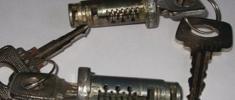
Core of ZZ VAZ 2109
On a VAZ 2109, replacing the core consists of the following steps:
- First, the protective and decorative cover is removed from the steering column, as well as the windshield washer and turn switches.
- The lock is secured with screws and a hook latch. There may be problems with unscrewing the screws, since their heads are cut off. To remove them, you first need to loosen them with chisels and then unscrew them with pliers. You can carefully drill out the screws.
- Next, we disconnect the clamps, disengaging them.
- By pulling out the side pin, you can remove the core. If that doesn’t work, the core can be drilled out using a thin drill. In extreme cases, you will have to dismantle the entire assembly.
- The next step is to disconnect the connector, wire plug, and ground wire.
- By releasing the latch, you can remove the cover and contact group.
- We insert a new core and check the work. When you turn the key, all processes should work.
The steering wheel lock should also be checked. If the steering wheel does not lock when turned fully, you need to adjust the position of the lock on the column.
Replacing the contact group of the VAZ ignition switch comes down to dismantling the ignition switch: the removal diagram is described above.
When performing the procedure, the following recommendations should be followed:
- before disconnecting contacts, it is advisable to assign numbers to them, this will help to avoid errors when connecting;
- If there is a retaining ring in the design of the contact group, you must first remove it using an awl.
Knowing how the ignition switch on a VAZ 2109 works, and having at least a little experience, you can carry out the repair yourself without resorting to the help of specialists. This way you can save on maintenance costs.
Video “Replacing ZZ”
This video demonstrates the repair of the ignition switch of a VAZ 2109 (the author of the video is Vitaly Rau).
To check the ignition switch, sequentially set the key to the positions at which the circuits indicated in the table should be closed.
When the key is turned to position “III”, the anti-theft device should be activated. When turning the key from position “III” to position “0”, the anti-theft device should turn off. This can be checked by turning the steering wheel.
When restarting from position “I” to position “II”, the locking is activated. The key can only be turned to position “II” from position “0”.
If there are defects, replace the contact group or ignition switch for VAZ 2109, VAZ 21099, VAZ 2108, Lada Samara.
Key position
Live contacts
Switched circuits
Outdoor Lighting. Instrument lighting. High beam headlight alarm
Generator excitation winding. Ignition system. Windshield cleaner. Carburetor idle speed solenoid valve control unit. Direction indicators. Reversing light. Control devices
Low and high beam headlights. Fog light. Headlight cleaners. Rear window cleaner. Heated rear window. Washer. Heater fan. Engine cooling fan
1.
Unscrew the six screws securing the lower steering column casing of the VAZ 21099.
2.
Remove the lower steering column cover.
3.
. and lining of the ignition switch for VAZ 2108, VAZ 2109, VAZ 21099.
4.
Remove the upper steering column cover.
5.
Disconnect the ignition switch wiring harness from the wiring harness.
6.
Disconnect the block with the ignition switch wires from the ignition relay for the Lada Satellite.
7.
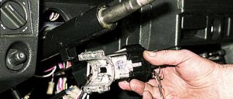
Insert the key into the ignition switch of the VAZ 2109 and turn it to position “0” to turn off the anti-theft device. Unscrew the four mounting bolts (two bolts are located on top of the column). Remove the bracket and ignition switch for the Lada Samara (see notes 1 and 2).
Note 1
If the bolt heads are sheared off, the bolts must be drilled out or removed using a screwdriver and hammer.
Note 2
Some cars are equipped with an ignition switch secured with two bolts. There is a slot at the top of the bracket that accepts the hook on the ignition switch housing.
8.
Unscrew the screw securing the switch cover.
9.
Remove the switch trim by pressing out the two plastic latches with a screwdriver.
10.
Remove the contact group.
11.
Assembling and installing the VAZ 2108 ignition switch is carried out in the reverse order.
Welcome! The ignition switch breaks quite rarely, but it still happens. After a lock breaks, it of course needs to be replaced with a new one, but how to do this, you ask? Some people still know the answer to this question, but some do not. For those who don’t know, we have prepared this article, which will describe in detail the process of replacing the ignition switch. And at the end of this article you will find a video clip that will describe in detail the process of replacing this lock.
Note! To replace the ignition switch, you will need the following tools: First, you will need screwdrivers, and you will also need a drill, a small hammer, pliers, and you will definitely need to stock up on a chisel!
Summary:
When do you need to change the ignition switch and contact group? It must be replaced if it breaks, as well as if the key is lost, and even if the cylinder in the lock stops turning and is stuck in one place. The contact group must be replaced if it is deformed, and even if, after turning the key in the lock, the car’s engine stops starting.
Note! Before you immediately say that the contact group of the lock is to blame for everything, first check the contacts of its wire blocks for functionality. (How to check the contacts of the contact group, see below in the section: “Checking the contacts of the wire block”)
How to replace the ignition switch, check the contact group and replace it on a VAZ 2108-VAZ 21099?
Replacing the ignition switch:
Removal: 1) Starting with “The battery is a rechargeable battery,” unscrew the nut that holds the “-” terminal on the battery and then remove the terminal. (How to remove the negative terminal from the battery, see the article about “Replacing the battery on a VAZ”, in the “first” paragraph)
2) Then remove the steering column cover and both steering column switches. (How to remove the casing and both switches, see the article: “Replacing under-steering switches”)
- Further, for clarity, the operation will be shown with the steering wheel removed, but you can still remove the ignition switch without removing the steering wheel.
3) Next, insert if the lock allows it, then insert the ignition key into it and put it in position “0”.
Note! The key must be installed in this position only to disable the anti-theft device!
4) Now remove the four bolts that secure the ignition switch. If you have these bolts with a cut off head, then knock them down with a hammer and chisel. (Be sure to read the “Important!” paragraph)
Note! If that doesn’t work, then try drilling out all four bolts, but just do it carefully without damaging anything!
5) Once the bolts are loosened, use pliers to remove them from the hole.
6) Next, remove the bracket on the left side, and the ignition switch on the right.
7) Now disconnect the wire block from the electrical connector.
 And finally, crawl under the dashboard, and there, disconnect the connector going from the ignition switch to the relay.
Installation: Installation of a new lock is carried out in the reverse order of removal.
Checking the contacts of the wire block:
1) First, remove the lock from the car using the text above.
2) Next, using an “Ohmmeter” or a “Multi-meter” with the “Ohmmeter” function enabled on it, connect its leads to the electrical connector and then look at the readings of the device.
Note! The device should clearly display “0”; otherwise, replace the contact group!
Replacing the contact group:
1) First, on the removed ignition switch, use a screwdriver to unscrew the screw that secures the ignition switch cover.
2) Then use a screwdriver to press out the two plastic latches securing the lock cover.
3) Then remove the cover.
4) And finally, remove the contact group from the ignition switch.
Note! Installation of the contact group is carried out in the reverse order!
Important! Not on all cars of the Samara family the ignition switch is attached to the steering column with four bolts; on some cars it is attached only with two bolts and on top it is secured with a hook indicated by a red arrow!
Additional video material: Below we have prepared a video related to replacing the ignition switch on cars of the Samara family.
Troubleshooting Methods
There are two methods for detecting faults:
- Visual;
- Diagnostic.
Ignition switch diagram
We suggest studying a visual method for determining a malfunction or breakdown of the contact elements of the ignition switch using the table.
| Action | The device is working properly | The device is faulty |
| Turn the key to the right position (ignition) | All electrical equipment turns on | All or part of the electrical equipment does not work |
| Turn the key to the second position | The starter is spinning | The starter does not work, the traction relay does not click under the hood |
But diagnostics allows you to get a more detailed answer. In addition, a visual inspection will not give you the opportunity to find all the reasons that could cause the ignition switch to break down.
To work, you will need a mini-tester and a multimeter in ohmmeter mode:
- Disconnect the power supply from the ignition switch. To do this, you need to remove the skin from the steering column;
- Switch your multimeter to an ohmmeter;
- On the block coming from the lock you need to find pins 7 and 4, which correspond to pins 15 and 30;
- Connect the multimeter probes to them;
- Turn the key to the “Ignition” position;
- On the block, find pins 7 and 3, corresponding to 50 and 30. Also connect a multimeter to them;
- Turn the key to the second position - Start the engine;
- If serviceability is present, the device will show zero resistance in both test cases.
