Colored wiring diagrams for the VAZ 2110 (injector and carburetor engine) are provided with a description of all elements for various modifications. The information is intended for self-repair of the car. Electrical circuits are divided into several blocks for ease of viewing via a computer or smartphone; there are also circuits in the form of a single picture with a description of the elements - for printing on a printer in one sheet.
There are two types of electrical wiring for the VAZ-2110: carburetor and injector. There are slight differences, but the basic principles of operation and wiring are the same. Depending on the location, the wiring differs into: under the hood and in the cabin. All electrical equipment of the car is connected using wires of a certain color. Each element has its own wiring harness through the blocks and fuses.
VAZ 2110 - modifications
VAZ-21100 . The base model which was produced from 1996 to 2000. The car was equipped with an 8-valve carburetor VAZ-21083 engine with a displacement of 1.5 liters and a power of 69 horsepower.
VAZ-21101 . This modification has been produced since 2004, equipped with an 8-valve gasoline injection engine with a displacement of 1.6 liters.
VAZ-21102. Like the previous modification with an 8-valve injection engine, but with a volume of 1.5 liters.
VAZ-21103 . Modification of the “tens” with a 16-valve injection engine with a working volume of 1.5 liters.
VAZ-21103M . A restyled modification of the VAZ-21103, equipped with a 16-valve petrol injection engine with a displacement of 1.5 liters and a power of 92 horsepower. Produced since 2002.
VAZ-21104 . The modification is equipped with a 16-valve petrol injection engine with a working volume of 1.6 liters.
VAZ-21104M . A restyled modification of the VAZ-21104, equipped with a 16-valve petrol injection engine with a displacement of 1.6 liters. Produced since 2004.
VAZ-21106 GTI . The engine of the VAZ-21106 GTI is the most powerful and expensive modification that has been produced since 2000. The car was equipped with a 2-liter 16-valve Opel C20XE gasoline engine with a capacity of 150 horsepower. The car was fitted with a body kit with swollen arches, and the track was widened by 76 millimeters. It was equipped with R15 wheels with low-profile tires.
VAZ-21106 Coupe . Coupe VAZ-21106 in a coupe body. A distinctive feature of the car was the presence of only two doors, which were lengthened by 250 millimeters, while the body was shortened by 170 millimeters. The engine was installed the same as in the previous VAZ-21106 GTI model.
VAZ 21106 WTCC . A sports modification of the 106 model, it participated in the 2008 FIA WTCC international championship.
VAZ 21107 . Modification of a car for rally competitions. It was equipped with a welded safety cage and a different suspension design.
VAZ 21108 "Premier" . A modification with a body lengthened by 170 millimeters in the rear door area, which provided more convenient entry and exit of passengers. It was equipped with a 1.5-liter injection 16-valve engine.
VAZ 21109 “Consul” . 4-seater luxury limousine based on the VAZ-2110 car. In addition to the length of the body, the dimensions of the rear door were also increased, for more convenient entry and exit of passengers. Equipped with a 1.5 liter engine and R14 or R15 wheels. Overall dimensions: length – 4950 mm, width – 1700 mm, height – 1440 mm. Fuel consumption in the urban cycle is 9.5 liters per 100 kilometers.
VAZ 2110-91 . Modification of the VAZ-2110 with a 1308 cm3 rotary piston engine. The car could reach speeds of up to 240 km/h, and acceleration from 0 to 100 km/h took 6 seconds.
A car with a 16-valve injection engine in the “Gran Lux” configuration includes:
- Electric windows;
- Door locking;
- Trunk lock lock;
- Velvet seat upholstery;
- Immobilizer;
- Heated front seats;
- Ventilated 14-inch brake discs;
- Rear spoiler with additional brake light;
- Fog lights.
Modernization of standard lights
Now it’s time to start tuning the rear lights of the VAZ 2110. The easiest option to improve the appearance of the car is to replace the standard lights with, for example, Osvar sticks.
Rear LED lights for VAZ 2110 “stick” type
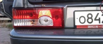
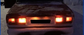
This is not difficult to do. We go to the store, buy them, remove the standard ones (see section “Removing block headlights”), and put the purchased ones in their place. As a rule, there is no need to make any modifications to the connectors or solder connections. Moreover, the “sticks” from the 112 model will fit perfectly on the VAZ 2110. The result will be something like this:
“Sticks” installed instead of the standard rear lights of the VAZ 2110
But we don’t look for easy ways, especially if we like to do things with our own hands and according to our own ideas. You can modify and modify the standard taillights, but to do this you will have to disassemble them.
How to take them apart
According to the designers' idea, the rear lights of the VAZ 2110 are non-separable - the glass is tightly nailed to the headlight body. Maybe with some creepy solvent like dichloroethane or using ultrasonic or microwave welding. But we will still try to disassemble the device, and in such a way that it can be assembled afterwards.
To work, we will need the headlight itself, a knife that we don’t mind, and a gas stove or any other burner.
Since glass cannot be removed by any other methods, we will literally cut it off. We remove the board with the light bulbs from the device. We heat the knife and begin to slowly cut off the glass around the perimeter.
Cutting off the rear light glass of a VAZ 2110 with a hot knife
We cut through on three sides - on the side of the side lamp and on the sides. We don’t touch the top side, because there the glass overlaps with the lantern body, and it won’t be possible to cut it off neatly.
The glass is placed on top of the device body
After making several passes with a knife, we begin to disconnect it at the top. We insert the knife, as shown in the photo below, and gently rock it, trying to tear the glass away from the body at the gluing site.
Removing the glass at the top of the headlight
After the glass comes off on top, there will be two more places that hold it. They are marked with arrows in the photo below. We do the same: we insert a knife between the glass and the body in the place where it still holds, and tear it off with light rocking.
Peeling off of glass in the area of the reflector
If everything is cut well, the glass can be easily removed.
Removing glass from the rear light of a VAZ 2110
All that remains is to bring beauty. Take a file and align the melted edges of the glass and body.
All that remains is to remove these melted burrs
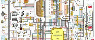
Wiring diagram for VAZ 2110 carburetor
In the instrument panel wiring harness, the second ends of the wires of white, black, orange, white with a red stripe and yellow with a blue stripe are connected to each other at the same points. The bends of the wires at the points of entry into the harness indicate the direction of their laying in the bundle.
See the complete diagram in one file below (click to enlarge):
1 – headlight 37 – instrument cluster 2 – front brake pad wear sensor 38 – rear fog light switch 3 – fan motor switch 39 – fog light indicator lamp 4 – engine cooling system fan electric motor 40 – rear window heating indicator lamp 5 – sound signal 41 – clock 6 – generator 42 – rear window heating switch 7 – oil level sensor 43 – steering column switch 8 – carburetor solenoid valve control unit 44 – block for switching wires when installing headlights of another type 9 – heater controller 45 – switch instrument lighting 10 – recirculation valve switch 46 – ignition switch 11 – illumination lamp for heater control levers 47 – connectors for connecting the headlight cleaner wiring harness 12 – switch 48 – socket for a portable lamp 13 – carburetor limit switch 49 – directional light 14 – control sensor oil pressure lamps 50 – brake light switch 15 – spark plugs 51 – interior lamp 16 – carburetor solenoid valve 52 – on-board control system unit 17 – coolant temperature indicator sensor 53 – fuel level indicator sensor 18 – ignition distributor 54 – hazard warning switch 19 – ignition coil 55 – driver’s seat belt sensor 20 – starter 56 – cigarette lighter 21 – heater fan motor 57 – ashtray backlight lamp 22 – additional resistor for heater motor 58 – glove compartment light switch 23 – speed sensor 59 – connector for on-board computer 24 – reverse light switch 60 – glove box lighting lamp 25 – micromotor gearbox for heater flap drive 61 – side turn signal 26 – recirculation valve 62 – switch in the front door pillar 27 – brake fluid level sensor 63 – switch in the rear door pillar 28 – pads for connecting the rear window washer motor 64 – parking brake warning lamp switch 29 – battery 65 – trunk light 30 – windshield washer motor 66 – interior air temperature sensor 31 – washer fluid level sensor 67 – external rear light 32 – level sensor coolant 68 – internal rear light 33 – windshield wiper motor 69 – license plate light 34 – mounting block 70 – block for connecting the rear window heating element 35 – blocks for connecting the warning light harness 71 – block for connecting an additional brake signal 36 – outdoor light switch
Tuning
First, let's try to insert Priora LED boards into our disassembled headlight. Such boards can be found on sale without reflectors; you can buy additional reflectors for each LED, or you can find a whole module with original reflectors at disassembly, so the matter is simplified. This board will be responsible for the dimensions and fog lights. Let's leave the turn signal as is.
Rear light board with LEDs and reflector from Lada Priora 2
Since we are not interested in the direction indicator, we will not remove the glass, but only the part of the body responsible for the side light. To do this, we will use a circular saw attachment and a piece of regular blade. If you don’t have a file, you can get by with just one blade.
First, using a saw, we cut off half of the body, responsible for the side light, from the glass.
Cutting the taillight housing from the glass
Now we arm ourselves with a hacksaw blade and cut the rear light housing in half.
Cutting the body with a hacksaw blade
We use a knife to undermine the places where the glass is attached to the body in the area of the reflector (see the section “How to disassemble them”). Remove half of the body.
The removed half of the rear light housing of a VAZ 2110
Again, we take the canvas in our hands and cut off that part of the body that previously covered the reflector (reflector). It will interfere with putting the case in place after installing the LED Prior board.
This piece of the body needs to be cut down
We clean all burrs with a file or sandpaper. Now the most important operation. The result will depend on the thoroughness of its implementation. It is necessary to remove all these diverging microlenses from the inside of the glass, making it completely transparent.
To do this, we will use grinding attachments on a drill. They are easy to buy at any relevant store. We carry out first rough, then fine grinding.
Removing diverging lenses from the inside of the glass
We polish and get absolutely transparent glass.
After polishing, the glass is completely transparent
We insert our board from Priora VAZ 2112 into the glass.
The board fits into the glass like a glove
We install the sawn half of the body in place, grab it in several places with a soldering iron (temporarily so that the structure does not fall apart). Fill the seam with sealant.
Reinstalling the rear light housing
When the sealant has dried, we admire the work done.
The result of our tuning
All that remains is to connect the board instead of the standard lamps. We remove the side and fog light bulbs from the board, leaving the turn signal lamp. We solder the wires from the LED board directly to the conductive busbars of the lamp board, focusing on the diagram included with the product.
You can power the LED insert directly from the standard board
We connect, install the rear light in place, and check.
More options
This, of course, is not the only tuning option. Instead of the Prior board, you can install almost any LED modules or even an LED strip of appropriate power.
You can put, for example, these modules in a flashlight:
You can secure them in the housing using the same sealant or even a heat gun. The result will not be as good, and if you polish the glass, the modules will be visible through it. But if you don’t grind the glass, then the tuning is quite good and, most importantly, much simpler than the previous option. The advantage of using such modules is that they have a built-in stabilizer (driver), which means they will last a very long time.
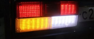
And here is the result of tuning the rear lights using a regular LED strip and a diode module installed instead of a reversing lamp.
Option for tuning the rear lights of the VAZ 2110
In the next option, the LED strip is glued directly to the glass using double-sided transparent tape, but, of course, you can also use transparent sealant. The result is not so great, but it is cheap, easy and cheerful.
Option for tuning the rear light with LED strip
And these lanterns look very original, although, you must admit, a little collective farm.
Diamond-shaped side lights
Tinting
The next tuning option is tinting. We will only tint the “stick”. To do this we need a tint film and a small rubber spatula. Such spatulas are used for body filler.
To tint you need a film and a spatula
What is the beauty of this tuning: you don’t need to tear the tail light to pieces or even dismantle it. We will tint the outside of the stick. We cut off a piece of film for the lamp located in the body.
Cut the required piece of film
Wash the taillight thoroughly and apply a mild soap solution to it or simply wet it. We apply the film and, gradually removing the protective layer, carefully smooth it out first with our hands, and then with a spatula from the center to the edges, expelling water from under the film. To better adhere the film to the glass, you can use a hairdryer.
Applying tint film
We take a mounting knife and cut off the excess film, leaving it only on the “stick”.
Trimming excess film
We remove the cut film and go over the glued one again with a spatula, paying special attention to the cut edges. We repeat the operation on the flashlight, which is located in the trunk.
Pasting the film on the additional rear light
This is the result of our work. It looks much more solid and presentable than the original one.
Tinted “stick” of the rear light of the VAZ 2110
So we got acquainted with the rear light of the VAZ 2110 car and all the tricks associated with it. Now it won’t be difficult for us to replace the light bulbs in it, dismantle it and even disassemble it for tuning.
Diagram of VAZ 2110 injector 8 valves
1 – headlight 2 – front brake pad wear sensors 3 – horn 4 – cooling system fan 5 – reverse light switch 6 – battery 7 – generator 8 – oil pressure warning lamp sensor 9 – oil level sensor 10 – spark plugs 11 – injectors 12 – idle speed control 13 – electronic control unit blocks 14 – throttle position sensor 15 – crankshaft position sensor 16 – ignition module 17 – coolant temperature indicator sensor (for instrument cluster) 18 – starter 19 – diagnostic block 20 – coolant temperature sensor (for the engine management system) 21 – speed sensor 22 – fuel pump switch relay 23, 35, 39 – fuses 24 – electric fuel pump 25 – micromotor gearbox for heater damper drive 26 – recirculation valve 27 – heater fan 28 – windshield washer pump windows 29 – washer fluid level sensor 30 – brake fluid level sensor 31 – coolant level sensor 32 – windshield wiper gear motor
33 – additional heater fan resistor 34 – injection system power supply relay 36 – canister purge valve 37 – mass air flow sensor 38 – cooling system fan activation relay 40 – external lighting switch 41 – knock sensor VAZ-2110 injector 42 – oxygen concentration sensor ( heated lambda probe) 42* – CO potentiometer (installed on cars running on leaded gasoline; in this case, an oxygen concentration sensor is not installed) 43 – fog light indicator lamp 44 – rear window heating indicator lamp 45 – fog light switch 46 – rear window heating switch 47 – instrument cluster 48 – mounting block 49 – fuel level sensor 50 – ignition switch 51 – instrument backlight brightness control 52 – steering column switch 53 – heater control lever illumination lamp 54 – hazard warning switch 55 – electronic heater control unit; 56 – recirculation valve switch 57 – on-board control system display unit 58 – side direction indicators 59 – temperature sensor for the heating system 60 – interior lamp 61 – front interior lamp 62 – socket for a portable lamp 63 – electronic clock 64 – switches in the racks front doors 65 – switches in the rear door pillars 66 – glove compartment lighting lamp 67 – glove compartment lighting switch 68 – cigarette lighter 69 – ashtray lighting lamp 70 – brake light switch 71 – rear window heating element 72 – external rear lights 73 – internal rear lights 74 – license plate lamps 75 – trunk lighting lamp
See the complete diagram in one file below (click to enlarge):
Replacing lamps
We have figured out the type of lamps, what we know to buy for replacements, now we will find out how to replace them. Let's start with “stops” and reverse.
Brake and reverse lights
We open the trunk lid, look under it and see the back of the lamp. Squeeze the two latches at the edges and remove the board with the lamps. The power connector does not need to be disconnected - the length of the wires is quite sufficient for this operation.
Removing the board with lamps
We find the desired lamp, guided by the picture at the beginning of the article, slightly recess it, turn it counterclockwise and remove it from the socket. We install a new one in place of the burnt one and fix it by turning it clockwise.
Replacing the reverse lamp on a VAZ 2110
Turns, dimensions and fog lights
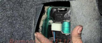
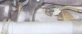
Let's move on to the rear light of the VAZ 2110 installed in the body. Here we have to replace the turn indicator lamps, side lights and fog lights. We open the trunk lid and opposite the lamp in the upholstery we find a valve with Velcro. We open it and see the back of the lantern.
The rear part of the tail light of the VAZ 2110 is closed by a valve in the upholstery
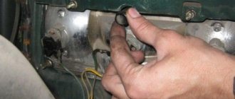
At the top and bottom we find two latches. Push them towards the center of the lantern.
The board with lamps is secured using two latches
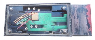
We take out the board with the light bulbs. On the removed board we see 3 turn signal lights and two more nearby: a large one for the fog light and a small one for the side light.
The power supply does not need to be disconnected when removing the board - the length of the wiring harness is sufficient for this operation.
Removed board with light bulbs
All three light bulbs are removed in the same way - by lightly pressing and turning counterclockwise. We take out the burnt one.
Turn signal lamp removed
We install a new one in its place and fix it by pressing and turning clockwise. We return the board to its place, snap it into place with the latches, and close the back of the lamp with the trunk trim flap.
Diagram of VAZ 2110 injector 16 valves
1 – headlight unit 35 – instrument lighting switch 2 – front brake pad wear sensors 36 – ignition switch 3 – reverse light switch 37 – mounting block 4 – engine cooling system fan electric motor 38 – recirculation valve switch 5 – sound signal 39 – controller heater 6 – right front door locking motor 40 – hazard warning switch 7 – power window relay 41 – heater control lever illumination lamp 8 – 8 A fuse 42 – glove compartment lighting lamp 9 – starter 43 – glove compartment lighting lamp switch 10 – battery 44 – cigarette lighter 11 – generator 45 – on-board control system display unit 12 – windshield washer motor 46 – ashtray lighting lamp 13 – washer fluid level sensor 47 – brake signal switch 14 – left front door locking motor 48 – locking motor left rear door 15 – power window switch of the left front door 49 – power window switch of the left rear door 16 – coolant level sensor 50 – power window motor of the left rear door 17 – windshield wiper motor 51 – socket for a portable lamp 18 – recirculation valve 52 – clock 19 – micromotor gearbox for heater flap drive 53 – gearmotor for electric window lift of the right rear door 20 – electric motor for heater 54 – power window switch for the right rear door 21 – trunk lock switch 55 – gearmotor for locking the right rear door 22 – power window switch for the right front door 56 – side turn signal 23 – electric window motor of the right front door 57 – parking brake warning lamp switch 24 – door lock system control unit 58 – driver’s seat belt sensor 25 – additional resistor for the heater motor 59 – directional lamp 26 – brake fluid level sensor 60 – interior lamp 27 – electric window motor of the left front door 61 – interior air temperature sensor 28 – exterior lighting switch 62 – switch in the front door pillar 29 – instrument cluster 63 – switch in the rear door pillar 30 – rear fog light switch 64 – external rear lamp 31 – control lamp fog light 65 – interior rear light 32 – rear window heating indicator lamp 66 – license plate lights 33 – rear window heating switch 67 – trunk light 34 – steering column switch A – blocks for connecting the rear window washer motor B – blocks for connecting the harness injection system C – to the warning light harness connector D – connector for connecting to the on-board computer E – to the headlight cleaner harness connector F – connector for connecting to the fuel level sensor in the electric fuel pump module G – to the rear window heating element H – connector for connecting an additional signal braking J – to the trunk lock motor
Useful: VAZ-2104 diagram
See the complete diagram in one file below (click to enlarge):
Removing the car dashboard
- Using a Phillips screwdriver, remove the three screws that secure the center console;
- remove the cover, the protrusion located at the bottom, remove the protrusion from the bracket;
- Using a nozzle, unscrew the five screws located in the console on the right and remove the screen;
- Disconnect the terminal with the (-) sign from the battery. If there is a radio receiver, you need to remove it, remove the plug from the shield;
- Disconnect the wires coming from the cigarette lighter, remove the cartridge;
- Using a narrow screwdriver, remove the handle from the levers;
- pull the handle towards the heating and fan switch;
- unscrew the two screws above the panel and the two located under it using a screwdriver;
- unscrew the screw located behind the panel;
- Also unscrew the two self-tapping screws securing the cover;
- disconnect the harness and wire connectors. To avoid confusion when installing the panels, you should mark the order in which they are connected;
- unscrew the fastening bolts;
- unscrew the two self-tapping screws, those that secure the bottom bracket using an 8 key;
- unscrew the self-tapping screw securing the light guide and remove it;
- Also unscrew the screws securing the heating unit;
- remove lamp sockets;
- after removing the external parts, remove the decorative insert;
- unscrew all nuts with a 21 key;
- hydrocorrector, remove its lamp;
- Unscrew the screws that are attached to the cross member on the left.
- Finally, the panel itself is removed. The panel is assembled accordingly in the reverse order.
In general, the repair work is quite doable even with your own hands, but before starting dismantling work, you need at least a pinout mapped on paper, otherwise it will be difficult: you will need to “trace” every wire and every connection that is on the “path” from devices to the power button.
Electrical circuit of ECM VAZ-21101
1 – VAZ-21101 controller; 2 – block of the ignition system harness to the ABS cabin group harness; 3 – diagnostic block; 4 – immobilizer warning sensor; 5 – immobilizer control unit; 6 – ignition coil; 7 – spark plugs; 8 – nozzles; 9 – electric fuel pump; 10 – block of the ignition system harness to the fuel level sensor harness; 11 – block of the fuel level sensor harness to the ignition system harness; 12 – block of the ignition system harness to the injector harness; 13 – injector harness block to the ignition system harness; 14 – speed sensor; 15 – idle speed regulator; 16 – throttle position sensor; 17 – coolant temperature sensor; 18 – mass air flow sensor; 19 – oil pressure warning lamp sensor; 20 – phase sensor; 21 – oxygen sensor; 22 – crankshaft position sensor; 23 – knock sensor; 24 – solenoid valve for purge of the adsorber; 26 – coolant temperature indicator sensor; 27 – ignition system harness block to the instrument panel harness; 28 – instrument panel harness connector to the ignition system harness; 29 – controller power supply fuse; 30 – ignition relay; 31 – ignition relay fuse; 32 – fuse for the power supply circuit of the electric fuel pump; 33 – electric fuel pump relay; 34 – electric fan relay; 35 – ignition system harness block to the air conditioner connector; 36 – block of the ignition system harness to the side door harness. 37 – electric fan of the cooling system; 38 – diagnostic connector; 39 – ignition switch; 40 – instrument cluster; 41 – on-board control system unit; 42 – starter relay; 43 – contacts of the 8-terminal blocks of the instrument panel harness and the front harness; 44 – contacts of the 21-terminal blocks of the instrument panel harness and the rear harness; 45 – trip computer.
- A – to the “plus” terminal of the battery;
- B1 – grounding point of the fuel level sensor harness;
- B2, B3 – grounding points of the ignition system harness;
- C – to the starter;
- D – to the driver’s door interior lamp switch.
Fuse and relay box
The fuse and relay box is located on the left, lower part of the instrument panel. It is accessible by pressing the button and folding the lid down. To remove fuses, there are special non-conductive pliers in the upper left part of the mounting block.
1 - K5 - high beam relay . If the high beams in two headlights do not work, check this relay. If one of the high beam headlights does not work, check fuses F3 and F13, as well as the lamps and the high beam switch.
2 - K4 - low beam relay . If the low beam in both headlights does not work, check this relay. If only one low beam headlight does not work, check fuses F2 and F12, as well as the lamps themselves and the light switch.
3 - K1 - lamp health control relay.
4 - non-conductive tweezers for removing fuses.
5 - power window relay . If your power windows stop working, check this relay. It could also be in fuse F5, or in the window lift drive system itself. To get to the mechanism, you need to remove the door trim. Check the electric motor, the appearance of the gears and the absence of binding of the mechanism.
6 - K3 - turn signal and hazard warning relay . If your turn signals or hazard lights do not work, check this relay and fuse F16, as well as the turn signal lamps themselves and their switch.
7 - starter relay . If the car does not start and the starter does not turn, check this relay. It could also be a dead battery, as well as the starter mechanism itself.
8 - backup fuses.
9 - fog lamp relay . If the fog lights do not work, check this relay and fuses F4 and F14. Also check their connection diagram, the serviceability of the wiring and connectors, as well as the lamps in the headlights and the power button.
10 - K2 - windshield wiper and washer relay . If your windshield wipers or windshield washer are not working, check this relay. Also check the wiper motor, washer pump and washer fluid level in the washer reservoir.
11 - K7 - rear window heating relay . If the heating does not work and the rear window fogs up, check this relay and fuses F8 and F9. Also check the connection contacts to the terminal points of the heating elements (at the edges of the glass at the rear pillars). If everything is in order, but the heating does not work, the issue may be in the wiring (the wires are frayed or something else).
12 - K6 - add. relay, ignition relay . If your ignition does not turn on or is having problems with it, check this relay. This relay protects the ignition switch contacts from burning. Also check the ignition switch itself and the contact group.
13 - row of fuses F1-F10
14 - row of fuses F11-F20
Engine control circuit VAZ-21102, 21103
Engine control circuit for VAZ-21102, VAZ-21103 (controller M1.5.4N, “January-5.1”).
1 - injectors 2 - spark plugs 3 - ignition module 4 - diagnostic block 5 - controller 6 - block connected to the instrument panel wiring harness 7 - main relay 8 - fuse connected to the main relay 9 - electric fan relay 10 - fuse connected to electric fan relay 11 – electric fuel pump relay 12 – fuse connected to the electric fuel pump relay 13 – mass air flow sensor 14 – throttle position sensor 15 – coolant temperature sensor 16 – idle speed regulator 17 – VAZ-21102 oxygen sensor 18 – knock sensor 19 – Crankshaft position sensor 20 – canister purge solenoid valve 21 – immobilizer control unit 22 – immobilizer status indicator 23 – vehicle speed sensor 24 – electric fuel pump with fuel level sensor 25 – oil pressure warning lamp sensor 26 – coolant temperature indicator sensor 27 – level sensor oil 28 - phase sensor (installed on a car with a 16-valve engine) A - block connected to the wiring harness of the anti-lock brake system (ABS) B - block connected to the air conditioner wiring harness C - block connected to the electric fan wiring harness D - wires , connected to the ignition switch (backlight lamp) E - block connected to the blue-white wires disconnected from the ignition switch (when installing the immobilizer) F - to the “+” terminal of the battery G1, G2 - grounding points The diagram uses the designation of the element number circuit to which this wire is connected, for example “-4-”. In some cases, in addition to the designation of the element number, it is given through an oblique fraction and the contact number, for example “-5/15-”. The diagram does not show the connection points of the pink-black, red and green with a red stripe wires.
Pinout of 8-pin connector
- power supply
- speed sensor (electric speedometer)
- fuel consumption (for BC)
- coolant sensor
- emergency oil pressure
- check lamp
- oil level sensor
- tachometer signal
Wiring diagram for fog lights.
According to the factory connection diagram, the fog lights turn on after the headlights are turned on. In this case, you can leave the headlights on with the engine off, which will drain the battery. To prevent this situation, it is better to connect the relay control wire to the terminal from the ignition switch (red in the diagram). But if you want to leave the switch on together with the dimensions, then pin 30 of the relay is best connected to a wire receiving power through the ignition switch. It should be taken into account that the load on the ignition switch will increase.
Electrical circuit of ECM VAZ-21104
1 – block of the ignition coil wiring harness to the ignition system harness; 2 – block of the ignition system harness to the ignition coil wiring harness; 3 – ignition coils VAZ-21104; 4 – immobilizer warning sensor; 5 – immobilizer control unit; 6 – spark plugs; 7 – nozzles; 8 – diagnostic block; 9 – block of the ignition system harness to the ABS cabin group harness; 10 – controller; 11 – electric fuel pump; 12 – block of the ignition system harness to the fuel level sensor harness; 13 – fuel level sensor harness connector to the ignition system harness; 14 – block of the ignition system harness to the injector harness; 15 – injector harness block to the ignition system harness; 16 – block of the ignition system harness to the side door harness; 17 – speed sensor; 18 – idle speed regulator; 19 – throttle position sensor; 20 – coolant temperature sensor; 21 – mass air flow sensor; 22 – oil pressure warning lamp sensor; 23 – phase sensor; 24 – oxygen sensor; 25 – crankshaft position sensor; 26 – knock sensor; 27 – solenoid valve for purge of the adsorber; 28 – oil level sensor; 29 – coolant temperature indicator sensor; 30 – block of the ignition system harness to the instrument panel harness; 31 – instrument panel harness connector to the ignition system harness; 32 – ignition relay; 33 – ignition relay fuse; 34 – fuse for the electric fuel pump power supply circuit; 35 – electric fuel pump relay; 36 – electric fan relay; 37 – controller power supply fuse; 38 – ignition system harness block to the air conditioner connector; 39 – instrument cluster; 40 – ignition switch; 41 – electric fan of the cooling system; 42 – on-board control system unit; 43 – starter relay; 44 – contacts of the 8-terminal blocks of the instrument panel harness and the front harness; 45 – contacts of the 21-terminal blocks of the instrument panel harness and the rear harness; 46 – trip computer; 47 – diagnostic connector.
- A – to the “plus” terminal of the battery;
- B1 – grounding point of the ignition coil wiring harness;
- B2 – grounding point of the fuel level sensor harness;
- B3, B4 – grounding points of the ignition system harness;
- C – to the starter;
- D – to the driver’s door interior lamp switch.
According to the scheme described above, fuel regulation in a car is carried out. Moreover, it depends not only on the load of the valves in the engine, but also on the corresponding position relative to the throttle valve. With the help of a diagram of electrical wiring and valves, it is possible to understand which of the relays or fuses is malfunctioning and replace it in time. In this case, one of the main roles when supplying fuel is played by electrical equipment (controllers) that regulates the operation of the injector.
Possible battery malfunctions
Over time, any battery becomes unusable due to wear and tear. Its service life largely depends on operating and maintenance conditions. If there is a problem, the VAZ 2110 battery light comes on on the instrument panel.
Battery indicator is on
The warning light may come on if the following problems occur:
- low electrolyte level in banks;
- Excessive heat causes the battery case to swell;
- the appearance of the smell of rotten eggs (that’s what sulfur smells like) indicates a battery leak, which is also characterized by oxidation of the terminals;
- low tension of the generator belt due to damage or wear;
- overheated fuse or poor contact in the connections of the mounting block;
- malfunction of the diode bridge, relay regulator;
- a break in the electrical network;
- oxidized contacts on the battery terminals or generator output;
- the brushes on the generator device are worn out;
- Poor contact of the ground wire.
To detect the causes of the malfunction, you need to diagnose the battery and test the entire electrical circuit of the car.
Electrical diagram of VAZ 2110
Circuit breakers
Now let's see which fuses are responsible for what in the same mounting block. I will also give the main reasons for troubleshooting.
F1 (5 A) - license plate lighting lamps, dashboard lighting, side lights on the panel, trunk lamp, left side lights . If any of the listed lamps do not work, check this fuse, as well as the lamps themselves and their contacts. If everything is in order, check the headlight switch button.
F2 (7.5 A) - low beam in the left headlight . If both low beam headlights do not work, also check relay K4 and the lamps themselves. It could also be the light switch and its contacts.
F3 (10 A) - high beam in the left headlight . If both high beam headlights do not work, check the K5 relay, the lamps themselves and the high beam switch knob.
F4 (10 A) - front fog lamp on the right side . If both fog lights do not work, check relay 9 and the headlight bulbs themselves, as well as the switch and its contacts.
F5 (30 A) - window lift motors . If the power windows do not work, check this fuse and relay 5. In winter, check if the windows are frozen, warm them up and clear them of ice if necessary. It could also be the window lift motor, its mechanism and gears; in order to get to it, you need to remove the trim of the desired door.
F6 (15 A) - portable lamp fuse.