How to change the generator relay in a gazelle
Checking and replacing brushes and voltage regulator on cars with engines of the ZMZ-405, ZMZ-406 type.
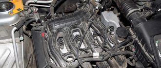
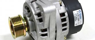
On engines of the ZMZ-406 and ZMZ-405 families, generators 9422.3701 or 5122.3771 with built-in integral voltage regulators are installed
Checking the serviceability of the voltage regulator
In order to verify that the voltage regulator is faulty, we turn off all consumers except the side light and measure the voltage at 1000...1200 min -1, which should be within 13.5...14.2 V.
Connect a 12V test lamp to the brushes.
Apply a voltage of 12 V “+” to the terminal, and “-” to the “ground” of the brush holder.
In this case, the control lamp should light up.
If the control lamp does not light, the voltage regulator must be replaced.
Replacing generator voltage regulator 9422.3701 or 5122.3771
The voltage regulator is made in a single housing with a brush holder.
Disconnect the battery.
Disconnect the wires from the generator terminals, remove the plug from the generator plug terminal.
Use a 10mm wrench to unscrew the nut.
Remove the capacitor wire ends from the “+” terminal of the generator
Use an 8 wrench to unscrew the capacitor mounting nut.
Using the “8” head, unscrew the two nuts securing the plastic casing of the generator
Remove the plug block from the output of the voltage regulator.
Using a short screwdriver, unscrew the two screws securing the regulator to the generator
Remove the voltage regulator assembly with brush holder
Install the new regulator in reverse order.
Checking the serviceability of brushes and brush holder
Check the protrusion “a” of the brushes from the brush holder.
If the free brush protrusion dimension “a” is less than 4.5 mm, replace the brush holder assembly with the voltage regulator.
We replace the brush holder with worn brushes as an assembly.
Gas 3110. Generator repair. Volga
Repairing a generator yourself is difficult and impractical, since a special stand will be required to determine its serviceability and compliance with its characteristics.
| NOTE During electrical tests of the generator, especially in the rectification stage, the equipment used should not produce voltages higher than 14 V to avoid the risk of destruction of some components. |
Therefore, it is better to entrust generator repair to qualified specialists at a service station, where you can also replace the generator from the exchange fund. Such a generator will be 50% cheaper than a new one.
However, before replacing the generator, you can carry out some checks.
Checking the voltage regulator
on a car
To check the voltage regulator, you must have a DC voltmeter with a scale of up to 15 - 30 V, accuracy class no worse than 1.0.
Check the voltage regulator installed on the car in the following order:
- start the engine and let it run for about 15 minutes at medium speed;
- using a voltmeter, measure the voltage between terminal “30” and the “ground” of the generator;
- The voltage should be between 13.3 - 14.6 V.
If there is a systematic undercharging or overcharging of the battery and the regulated voltage does not fall within the specified limits, the voltage regulator must be replaced. In addition, it is necessary to check the condition of the carbon brushes.
Checking the condition of the carbon brushes
Although this work can be done with the generator installed, it is still recommended to remove the generator from the vehicle.
Checking and replacing brushes and voltage regulator of a car with a ZMZ-402 engine
On cars with engines ZMZ-4025 and ZMZ-4026, generators 16.3701 or 191.3701 are installed, not equipped with a built-in voltage regulator.
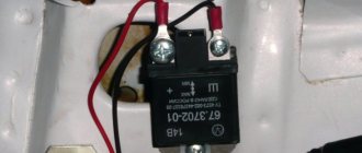
These generators operate in conjunction with an external transistor voltage regulator type 13.3702-01 or 50.3702, which has electronic protection against short circuits in the generator excitation winding circuit.
The regulator is installed in the engine compartment and attached to the engine compartment mudguard with two nuts.
The regulator provides a battery charging voltage of 13.4 - 14.7 V at a generator speed of 2800 - 12,000 min -1, corresponding to an engine speed of 1400 - 6000 min -1, a load of 5 - 40 A and a temperature from -20 to +80 °C.
At the “Ш” and “-” terminals of the regulator, the voltage drop should be no more than 1.6 V at a current of 4 A in the generator excitation winding circuit and a temperature of +20 °C.
Before checking the regulator, make sure that the generator belt tension is normal and that the regulator has good contact with ground (if necessary, adjust the belt tension and tighten the nuts securing the regulator to the body).
You should not connect additional electrical consumers to the power supply circuit of the generator excitation winding, since in this case the generator voltage increases greatly.
1. Before checking the voltage regulator, check the condition of the wires and the reliability of the connections between the generator, voltage regulator and battery.
It should be noted that the absence of charging current can be caused by the operation of the regulator protection circuit in the event of a short circuit in the generator excitation winding circuit. When the short circuit is eliminated, the operation of the voltage regulator is restored.
2. The voltage regulator can be checked on the car. To do this, you need a DC voltmeter with a measurement limit of up to 20 - 30 V and a division value of 0.1 - 0.2 V.
Start the engine and, maintaining the engine speed of 1700-2000 rpm, turn on the low beam headlights. In this case, the charging current according to the ammeter should be no more than 10 A.
If the ammeter shows a charging current greater than 10 A, turn off the low beam headlights and side lights.
Measure the voltage at the “+” terminal of the battery, it should be 13.9 - 14.6 V at a regulator temperature of +20 °C. If the voltage differs from the specified values, the voltage regulator is faulty and needs to be replaced.
1. Disconnect the plug from the voltage regulator.
2. Using a 10mm wrench, unscrew the two bolts securing the regulator. Under each of the bolts there are tips of “mass” wires
We remove and replace the regulator. We install the new regulator in the reverse order.
Removing and checking generator brushes
1. Disconnect the battery.
2. Disconnect the plug block from the brush holder.
3. Using a slotted screwdriver, unscrew the two screws securing the brush holder
4. Remove the brush holder. Install the new brush holder in the reverse order
Check the ease of movement of the brushes in the brush holder. If the brushes are stuck, remove the two mounting screws and remove the brush holder cover.
Clean the brushes and clean the holes in the brush holder. If the required result cannot be achieved, replace the brush holder assembly or brushes
Brushes with chips, cracks or other defects must also be replaced.
Check the protrusion “a” of the brushes from the brush holder in a free state.
If dimension “a” is less than 8 mm, replace the brush holder assembly or brushes.
Source
How long should a gazelle be charged? Auto Bryansk
Constant undercharging of the battery or its absolute discharge at the most inopportune moment is a headache for many car owners. One source of these problems may be the generator. But how to check it? Perhaps it's not his fault at all? Let's figure out together how much the generator must produce for the normal functioning of all car systems and maintaining the battery in a charged state.
How to check the operation of the generator
The battery in a car is an important element of the system, which is responsible for providing the car’s on-board network with electricity. The generator is used to charge the battery while it is active. Unstable operation of a device generating electricity causes a voltage drop in the network and failure to restore the capacity of the power source.
Normal generator performance means timely and complete replenishment of the battery charge level, which decreases under load. Checking the battery charge level from the generator is simple and can be done by the car owner himself.
Diagnostics of an automotive energy-generating device includes a visual inspection of the unit, its elements and related parts, as well as voltage and current measurements.
At least twice a year, you should check the tension of the drive belt, excessive weakening of which leads to a decrease in the performance of the generator, and sometimes can lead to breakdown of the device. Once a year, you can check equipment elements - fasteners, diode bridge, voltage regulator and others.
Timely maintenance of the battery will also guarantee the absence of problems - cleaning the terminals, adding distilled water.
Diagnostics of indicators such as voltage, current, resistance are also necessary twice a year. To carry it out, you will need special devices - a voltmeter, multimeter or load fork.
What kind of charging should go to the battery from the generator?
It is traditionally believed that 13.5-14.5V should be supplied by the generator to the battery and this is absolutely enough to replenish the battery costs.
It is worth considering that using a battery with a higher power in a car than the manufacturer recommends also requires the installation of a more productive generating device.
It is necessary to take into account the load that the generator must withstand - it is calculated based on the maximum indicators of all electrical appliances and car systems.
Do not forget that the charging current from the energy-generating device will allow you to start the car in the cold season. In order to avoid problems with starting the car, we recommend purchasing generating equipment, the charge current of which will be approximately 10% of the capacity of the power source.
That is, a battery of 100 A/h requires a generator that can produce 10A. Please note that for many cars, 100 amp equipment will operate at its maximum capacity, because the power consumption of the automotive system is in the region of 80 amps.
Therefore, the choice of a source generating energy must take into account both the battery capacity and network consumption.
How to check the alternator voltage on the battery
The potential difference can be diagnosed in two ways - directly at the generating equipment and through the battery. The generator is directly connected to the power source with a thick wire, therefore, to check the level of potential difference, you can measure the voltage at the power source. To do this, you will need special devices - a voltmeter, multimeter or load plug.
The wires of the first measuring instruments are connected to the battery in any sequence. The plug must be connected to the battery terminals with strict observance of polarity. It is generally accepted that the normal voltage in the network should not be lower than 12 volts. At idle speed without turning on all the electrical appliances of the car, this indicator should be at the level of 13.5-14V. A drop in voltage values to 13.3-13.8 volts is considered acceptable.
At the same time, using conventional testing equipment, you can check the resistance of the generator elements - rotor, stator and diode bridge. Diagnostics of rotary equipment is carried out by its winding. It is necessary to connect the probes of the device with slip rings. If the multimeter gives readings from 2, 3 to 5.1 ohms, then this element is working. The current consumption of the winding should be within 3-4.5 amperes.
Its normal resistance is 0.2 Ohm. The diode bridge is checked by the presence or absence of resistance, the indicators do not matter. The only thing worth considering is that there should not be a zero dimension. Measurements are carried out in pairs - positive output and all plates on this side or minus and all elements.
We remind you that for normal charging of a car battery, the voltage supplied by the generator must be from 13.5 to 14 volts.
How many amperes does a car alternator produce per battery?
The current strength required by the electrical system of each car is individual and depends on the number of electricity consumers and their values. And also the charge current must be sufficient to charge the power source.
It is worth noting that ampere readings appear only when there is a load in the vehicle’s electrical system and, accordingly, the battery is discharged. After starting the car engine, the charging current is about 6-10 amperes and drops over time, because the battery is charging, taking on the main energy consumption. If you turn on additional equipment - headlights, radio or heated mirrors, you can see an increase in the charging current values.
When purchasing a generator, pay attention to its technical characteristics, which the manufacturer indicates on the case - that’s where you will find information about the maximum current that will flow to the battery.
https://www.youtube.com/watch?v=ur7U2w-28K0
In the table below you can see the approximate current values that the generator shows at different loads.
Table 1. How many amperes the generator produces under load.
Signs of a generator malfunction
In modern cars, breakdowns of the electrical system are one of the most common. A large number of electronics requires particularly careful monitoring of the operation and condition of the generator and battery, because their failure can immobilize the car. The most common signs of a generator malfunction are:
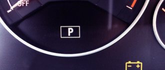
- battery indicator light on the instrument panel;
- unstable operation of the battery (its boiling over or undercharging);
- different intensity of headlights;
- extraneous sounds from the generator.
Source: https://autobryansk.info/skolko-dolzhna-byt-zarjadka-na-gazeli.html
sibay-rb.ru
The electrical equipment of this car is made according to a single-wire circuit: the negative terminals of devices and equipment are connected to the “ground” - the body and other mechanisms of the car, which play the role of a second drive. The on-board network of the Gazelle is 12V DC. To turn on the electrical circuit, use the ignition switch, which consists of a contact drive and an anti-theft lock. When the engine is not running, all electrical consumers take power from the battery, and when the engine is running, power is supplied from the alternator. While the element is working, the battery is charged, and the on-board circuit is powered through two fuses.
The lighting circuit is equipped with a 40 A fuse, and the circuit for additional equipment and mechanisms is equipped with a 60 A fuse. They are located in the engine compartment. Also, the circuits of all consumers are protected thanks to additional fuses with a lower current response. They are located under the dashboard on the driver's side.
The Gazelle generator is a synchronous three-phase machine with electromagnetic excitation and is designed to convert rotational motion into electrical energy. The car is equipped with models 2502.3771 or 9422.3701, the power of which is about 1000 W. Do-it-yourself installation of the generator on the Gazelle is carried out using a mounting bracket on the right side of the power unit. It is driven by a V-belt from the crankshaft ratchet. It works in tandem with a built-in voltage regulator Y212A11E, which maintains the output voltage in the specified operating mode.
Additional block
Under the hood of the gas 3110 on the left mudguard there is an additional block of two fuses:
p, blockquote 14,0,0,0,0 —>
- a 30A fuse protects the engine cooling fan circuit;
- A 60A fuse protects all circuits except the starter circuit.
p, blockquote 15,0,0,1,0 —>
To gain access, you must remove the unit cover.
p, blockquote 16,0,0,0,0 —>
And next to it there are some relays, for example, ignition and electric fan.
p, blockquote 17,0,0,0,0 —>
p, blockquote 18,0,0,0,0 —>
Possible faults
If the Gazelle generator malfunctions, the operation of all electronic devices is disrupted, and the battery is not recharged. A special indicator on the dashboard informs the driver about the breakdown of this part. With such a malfunction, starting the engine and driving the car is still possible, but until the battery is completely discharged. It is impossible to travel normally in such a car.
The main malfunctions of the generator include the following: violation of the integrity of the charging circuit wires, failure of bearings, damage to the diode bridge, short circuit of the stator winding, breakdown of the voltage regulator, wear of slip rings, excessive wear of brushes.
The Gazelle generator, like any car mechanism, can have both mechanical and electrical damage. Therefore, both the method of repairing the breakdown and the types of operations are different.
Mechanical damage includes wear and damage to rolling bearings, springs, damage to the integrity of the housing, pulley and drive belt.
Faults that are called electrical include breakage of the stator winding, cracks and wear of brushes, breakdown of the relay regulator, melting of the insulating coating of the turns, and interturn short circuits.
In case of any of these types of breakdowns, the car's generator does not fully perform its functions or completely fails, which affects the operation of all electronic devices and the engine as a whole.
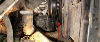
How to remove the generator on a Gazelle?
Now let's consider the issue of dismantling. When carrying out repair operations on a Gazelle car, removal of the generator must be carried out in accordance with all technological instructions and follow safety rules when carrying out work. If the car engine is hot, you need to let it cool down to avoid the possibility of getting burned.
If there is a malfunction of the generator, it is removed from the car engine and diagnostic and repair operations are carried out. To do this, you can contact service workshops or carry out repairs yourself. Many car enthusiasts who encountered this problem for the first time are wondering how to change the generator on a Gazelle. The operation of removing and installing this part is not a complex technological or repair process, and can be done at home. To do this you will need a standard set of tools.
Gazelle business 4216 - fuses and relays
Gazelle Business is a family of trucks and minibuses produced primarily with UMZ 4216 in 2010, 2011, 2012, 2013, 2014, 2015 and 2016. After that, Gazelle Business was restyled and the updated version was produced in 2022, 2022, 2022, 2022 and to the present. In this publication we will show a description of the fuses and relays of the Gazelle Business 4216 with block diagrams and photos - examples of their implementation. Note the fuse responsible for the cigarette lighter. In conclusion, we suggest that you read the complete operating instructions for Gazelle Business.
Removal process
Before replacing the generator on a Gazelle, it is important to remove the negative one, thereby de-energizing the car’s network, and also disconnect the electrical wires from the part. Next, you need to loosen the belt tension using a special mechanism and remove it. Then, having unscrewed the two mounting bolts of the generator from the engine crankcase, we remove the generator itself from the engine compartment.
If the brushes fail, replacing them will not be difficult.
You just need to unscrew the two screws securing the brushes and remove them from the body. But in case of more serious malfunctions, the element must be disassembled and a detailed analysis of the faults.
Disassembly
This section describes a step-by-step process that will help you correctly disassemble the Gazelle generator.
So, first you need to remove the plastic protective cover from the case. Then unscrew the brush block and the voltage regulator, having first disconnected the wiring from it. Next, you should unscrew the four tie rods of the generator housing and remove the housing cover together with the stator. Then, having disconnected the winding terminals from the diode bridge, you need to remove the stator, and, if necessary, the
You can carry out the process of diagnosing generator parts using measuring instruments: E236 or a special test light.
Checking the condition of parts
Regardless of which generator is installed on the Gazelle, the causes of the malfunction, as a rule, can be of the same nature.
They should not have chips or cracks; when pressed with a finger, they should freely sink into the channels of the brush holder, and return to their original position under the influence of a spring.
The length of the brushes should not be less than 4 mm, and if there is severe wear, they are replaced with new ones.
The stator is checked for short circuits between the turn windings and the housing.
This is done by connecting one terminal of the control light to the housing, and the second is alternately connected to one of the three terminals of the turns. In this case, if there is a short circuit to the housing, the indicator light will light up. Having discovered this type of malfunction, it is eliminated or the stator is completely replaced.
To check the stator for a short circuit between the turns, a test lamp is alternately connected to the two terminals of the windings. Moreover, if the light bulb lights up, then there is no break in the turns.
The generator rectifier unit should be cleaned of dust and dirt deposits. Next, you should check the diodes using a test lamp. Due to the fact that diodes of different polarities are placed in each section, they are checked with different battery connection polarities. If a faulty unit is detected, it is replaced.
Checking the generator after repair
After a detailed inspection and replacement of defective elements, the generator is assembled. Assembly occurs in reverse order. After the Gazelle generator is assembled, it is important to carry out diagnostics. The serviceable condition and correctness of its assembly can be determined by checking the rotation speed, during which the generator delivers a current of 40 A and 70 A. Diagnostics are carried out on a special stand. The electric motor of the testing stand smoothly changes the rotor speed. At the same time, the generator’s performance is measured, and the degree of its serviceability is determined.
Installing a dynamo on the engine
Installation on the engine is carried out in compliance with a certain technological process.
First, unscrew the fastening nuts of the generator brackets to the crankcase. Next, install the dynamo and secure the front mounting bolt. Then we move the front bracket and achieve alignment of the crankshaft ratchet with the drive flywheel of the part and the pump drive. By moving the bracket, we achieve elimination of the gap between the generator loop. Install the rear mounting bolt and firmly tighten the mounting nuts of the brackets to the engine crankcase. Next, we put the drive belt on the pulleys and tighten it using a tension bracket. We carry out a control check of the tightness of all threaded connections. We connect the part to the car's electrical network and put the terminals on the battery.
Checking the generator on a car
After installing the part in place, you need to start the car engine. Next, you need to turn on the maximum number of electrical appliances available in your vehicle (interior heater fan, wipers, car radio, interior lighting) and turn on the headlights. In this case, even at idle engine speed, the voltage in the on-board network should be 13.8 V. With this indicator, operating the car will not cause any problems.
So, we found out how to change the generator on a Gazelle.
In any car, the generator performs two important functions - it provides all consumers with the necessary electricity and recharges the battery. The Gazelle generator produces electrical alternating current, and the constant voltage required for the on-board network is achieved using a rectifier.
A lot depends on the performance of the energy source - it is impossible to operate a car with a faulty generator.
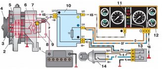
Generator circuit for Volga and Gazelle with engine 402
For Volga engines, generators were equipped with a double-row pulley, for Gazelles - with a single-row pulley.
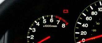
For cars produced in the first half of the 90s, an alternating voltage output from the generator phase was used to operate the tachometer.
In subsequent models, the tachometer received a signal from the ignition system, and the generator phase output was no longer needed; if the generator has one, it is simply not connected.
The generator has a traditional circuit. Winding, rotor, diode bridge, brush assembly. The voltage regulator type 13.3702 (131.3702) is separate and connected to the generator by wires.
Generator diagram for Volga with engine 402
Generator circuit for a Gazelle with engine 402
The circuit differs in that it uses a voltage ammeter to monitor the operation of the generator.
Gazelle generator circuit
The generator on Gazelle cars is a synchronous three-phase electric machine, in the excitation windings of which electric current is generated. The rotor (armature) rotates in the housing and is located inside a constant magnetic field, which is created by the stator (winding). Electricity is generated here as follows:
- when the engine starts, the movement is transmitted from the crankshaft through the drive belt to the generator set pulley;
- the rotor begins to rotate together with the pulley, a magnetic field arises between the stator and armature windings;
- due to electromagnetic induction, EMF is generated, alternating current appears;
- a diode bridge, consisting of diodes of different polarities, rectifies the electric current, making it constant;
- then the current from the rotor commutator is transferred to the brushes and supplied to the relay regulator;
- The regulator limits the voltage, ensuring safe operation of consumers.
The Gazelle generator circuit is very simple; the assembly consists of the following parts:
- case, it is made of two halves - aluminum front and back covers;
- fixed winding - stator;
- rotating shaft - rotor (armature);
- pulley and impeller;
- diode (rectifier) bridge;
- two bearings on which the armature rotates;
- brush assembly;
- relay regulator (voltage regulator).
It should be noted that the voltage regulator is not located directly on the generator on all Gazelle models; on cars with a ZMZ-402 engine, the relay regulator can be mounted on the side member.
Gazelle Euro 3 generator poor charging reason
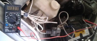
I measured the charge on the generator itself, how much does it give out?
measured at the terminals
They installed a known good battery for comparison...
Is the belt tensioned properly?
integral inside genes?
what is an integral?))
well, she’s got the brushes, she’s round... in the gazelle the gene is exactly ten-thousand...
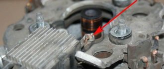
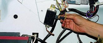
check it as in the picture, the light should be on
Will the diode work with the dimensions?
The diode will work, but you can reverse the polarity and it won’t light up. better lamp
OK! I'll go check it out now.
checked! connected the fog light - lights up
If the charging is half (he wrote 13.45 V), then it is either the stator winding (turn-to-turn, short to ground) or a diode bridge. Check the horseshoe with a tester, if everything is normal, then change the stator winding
How to check the bridge?
You separate the horseshoe from the stator. Let's call these places phases. First you apply +12V to the phase, hook the control with a crocodile to the minus of the power source with a probe to the thick positive terminal of the horseshoe, then to the negative terminal. In one case, the control should light up, in the other it should not. After checking all the phases “ “on the plus” we apply a minus, and you hook the control crocodile to the “+” of the power supply with a probe, first to the minus and then to the positive terminal of the horseshoe. During any tests, the control should first light up and then not (or vice versa). IT SHOULD NOT BE ON BOTH SIDES (the diode is broken) OR BOTH WILL NOT BURN (the diode is broken). I hope I explained it clearly
Types of Gazelle generators
The type of generator installed on Gazelle commercial vehicles depends on the engine model - the first GAZ-3302 vehicles had two types of engines:
The second generation of Gazelles began to be equipped with ZMZ-405 and Chrysler 2.4 engines; Gazelle Business cars, produced since 2010, are equipped with UMZ-4216 and Cummins engines, respectively, and other types of generator devices are installed on them.
Generators come in different capacities and are capable of producing currents of different magnitudes. The standard current source is calculated with a small power reserve, but additional electricity consumption is not taken into account here. Additional energy consumers can be:
- electric windows;
- electrical antenna:
- audio system;
- air conditioner;
- additional cooling fan in the cabin;
- additional heater motor.
If the generator turns out to be weak, it will not be charged enough, which may result in the battery being discharged. Therefore, in many cases, Gazelle owners try to install a more powerful current source - the car will not suffer in any way from the power reserve. For gazelles, there are generators that produce current 65/75/90/100/115/120/135 Amperes. There is a misconception that if the power of the generator device is high, the electrolyte in the battery may boil. But this is incorrect - the generator produces current depending on the load, and the excess voltage is limited by the relay regulator. A powerful generator has only two drawbacks:
- such an electric machine has a higher price;
- a dimensional unit may not always fit in size.
The generator, like any other part in the car, tends to break down; there are several types of malfunctions:
- charging disappears completely;
- there is an “undercharge”;
- high voltage appears in the network (more than 14.7 Volts);
- the generator starts to make noise.
There can be several reasons for the noise:
- bearings are worn out or defective;
- the drive belt has defects;
- The belt tension is weak, and therefore a whistle occurs;
- the impeller touches the belt or generator housing;
- pulley damaged;
- The generator fastener came loose.
If the voltage in the vehicle's on-board network is higher than the permissible norm, there is only one cause of the malfunction - the relay regulator has failed. For the same reason, there may be an undercharge - the voltage regulator does not cope with its functions.
If there is not enough charging, or it is completely absent, there may be several reasons for such problems:
- the brushes in the brush assembly are worn out;
- there are breaks or short circuits in the armature winding;
- these same defects are present in the stator winding;
- The diode bridge is faulty.
On a Gazelle car, the generator can be repaired quite easily, but if there are too many defects in it (for example, the rotor and stator are faulty at the same time), it is easier to buy a new unit and replace it.
Overcharging the battery from the generator, causes and solutions
Many car owners are faced with a situation where, after starting the engine, the on-board computer or one of the devices begins to show that the battery is being recharged.
The consequences of this situation are very different and depend on how much the voltage in the on-board network exceeds the nominal one.
Slightly increased parameters will only negatively affect the battery (boiling of the electrolyte followed by its evaporation), but if the voltage coming from the generator greatly exceeds the norm, then electrical consumers may fail.
In any case, overcharging is a phenomenon that must be eliminated, otherwise it will not have the best effect on the service life of the battery and electrical appliances.
Battery charging circuit
For a general understanding of the reasons for overcharging, first consider the battery charging circuit diagram. And although it is structurally different on different cars, the general principle of construction is the same.
This circuit includes:
- Generator;
- Rectifier block (diode bridge);
- Relay regulator;
- Fuse box;
- Egnition lock;
- Charge indicator lamp;
- Battery
The recharging system works using the example of the VAZ 2106 and other cars from the VAZ classic series as follows: after starting the power plant, by means of a belt drive, the crankshaft begins to rotate the generator rotor, as a result of which this unit begins to generate electricity.
But since automobile generators use alternating current, the generated energy goes to the rectifier unit, where alternating current is converted into direct current.
After the rectifier unit, the electricity goes to the relay-regulator, whose task is to maintain the voltage in a given range.
After the regulator, the electrical energy passes through the circuit through the fuse box, the ignition switch and the charge indicator lamp, then returns to the output of the generator, and from there it is supplied to the battery.
The detailed diagram is shown below.
Features of the circuit
The above is a general diagram of the circuit, without details, but it is enough to understand how everything works. Now about the features of battery recharging.
Alternator belt Gazelle
On Gazelle cars, the alternator belt drives the generator, thereby ensuring rotation of the rotor, thereby generating the electrical current necessary for the on-board network. Different engine models are equipped with different types and sizes of belts:
- ZMZ-402 – toothed or smooth poly-V belt, size – 10x1030 mm;
- UMZ-4216 - the same type as on the ZMZ-402 motor, size - 13x1040;
- ZMZ-406 (405) with power steering - multi-ribbed type, length - 1420 mm;
- ZMZ-406 (405) without power steering - multi-stream type, 1220 mm;
- Chrysler – poly-V-type, 1750 mm;
- Cummins 2.8 – multi-stream type, 1226 mm.
Depending on the engine model and manufacturer, alternator belts can vary in price; over time, they wear out and must be replaced. Since the belt drive also ensures the rotation of the water pump, when the generator belt is too tight, noise appears from the bearings of the pump and the generator itself. You can’t do a very weak stretch either:
- charging disappears;
- the water pump pumps weakly, and accordingly, the engine begins to overheat;
- A very unpleasant belt whistle appears.
For Gazelle and Sobol cars, generators are produced by different manufacturers, the most well-known companies are:
- ELDIX (Bulgaria);
- PRAMO-ISKRA (city of Rzhev);
- KZATE (old name KATEK, Samara);
- BATE (Belarus).
Relay block
In the cabin, under the panel, near the driver’s left foot, a relay block is mounted on the wall. Depending on the configuration and year of manufacture, different arrangements of elements are possible.
p, blockquote 11,0,0,0,0 —>
p, blockquote 12,0,0,0,0 —>
I can find it here:
p, blockquote 13,0,0,0,0 —>
- rear window defroster relay
- headlight high beam relay
- low beam headlight relay
- wiper relay
- heater motor relay
- horn relay
- fog light relay
- turn signal relay.
Generator replacement
The entire generator unit on a car is changed in the following cases:
- if many parts in the device require replacement, and repairing the unit is not economically profitable, it is easier and cheaper to buy a new generator;
- you need to go on a flight urgently, and there is no time to do repairs;
- a new generator is installed, and the old one is repaired and put away as a reserve - it is a backup.
The difficulty of replacing the generator unit also depends on the engine model, but on any engine the work is done quite quickly, since it is still simple on all brands of Gazelle cars. The easiest way is to replace the generator on a car with a 402 engine; we carry out the work as follows;
- After tensioning the belt, we secure the bolts and nuts to the end - they are now located under the generator, and getting to them is somewhat more difficult.
To fasten the generator securely, you need to install two nuts on the bolts, and be sure to lay it between the bolt and the nut along the engraver - on ZMZ-402 motors (as well as on UMZ-4216), vibration-proof fasteners tend to unscrew.
If the bearings in the generator wear out, noise (hum) appears in the generator unit. It is possible to drive with such noise for a while, but it is not advisable, and you cannot delay repairs for a long time - the bearings can jam and burn out. Bearings are always replaced on a removed generator, and in order to replace it, the generator assembly must be disassembled. You can do this kind of work yourself, but keep in mind that the bearings are pressed in and will require a special puller to dismantle them. The rear bearing is rigidly pressed onto the rotor shaft, and it is practically impossible to do without a puller.
In some cases, the bearing in the front housing cover boils tightly, and in this case it is easier to replace it together with the cover.
Electrical diagram Gas 3110
More information about the electrical equipment of the GAZ-3110 with the ZMZ-402 engine can be found in this electrical diagram, and the description for it is here.
p, blockquote 19,0,0,0,0 —> p, blockquote 20,0,0,0,1 —>
And if you have any questions, ask them in the comments.
The Volga and Gazelle were equipped with a ZMZ 402 engine. For this version of the car, a generator of type 16 KZATE or 19 ATE1 (Eltra) was used. These generators were completely interchangeable. They were identical in design and allowed the mutual use of parts for repairs.
How to check and replace the brushes of the generator and voltage regulator of a Gazelle car
Checking and replacing brushes and voltage regulator on vehicles with engines of the ZMZ-405, ZMZ-406 type
On engines of the ZMZ-406 and ZMZ-405 families, generators 9422.3701 or 5122.3771 with built-in integrated voltage regulators are installed.
In order to verify that the voltage regulator is faulty, we turn off all consumers except the side light and measure the voltage at 1000...1200 min -1, which should be within 13.5...14.2 V.
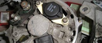
Connect a 12V test lamp to the brushes.
Apply a voltage of 12 V “+” to the terminal, and “-” to the “ground” of the brush holder.
In this case, the control lamp should light up.
If the control lamp does not light, the voltage regulator must be replaced.
The voltage regulator is made in a single housing with a brush holder.
Disconnect the battery.
Disconnect the wires from the generator terminals, remove the plug from the generator plug terminal.
1. Using a 10mm wrench, unscrew the nut. 2. Remove the capacitor wire ends from the “+” terminal of the generator. 3. Use an 8 wrench to unscrew the capacitor mounting nut.
An initial express check of the generator can be performed directly on the car.
Blocks under the hood
The engine control unit
Relay block diagram
Decoding
p, blockquote 13,0,0,0,0 —>
- Fuel pump relay
- Fan clutch relay
- Main relay
The starter relay is mounted on the front panel, next to the vacuum booster.
Fuse box
It is located on the battery mounting bracket, behind the closed cover.
Designation
p, blockquote 18,0,0,0,0 —>
| Fuse box on vehicles with ABS | |
| 1 | 90A UMZ-4216: Generator power circuit (connection of the generator with the battery), starter relay contacts, ignition switch, fuses F9, F10, F18, F21–F24, F26–F28, air conditioner circuit |
| 1 | 125A ISF2.8s4129Р: Air heater |
| 2 | 25A UMZ-4216: ABS control unit |
| 2 | 40A ISF2.8s4129Р: Car light circuit and air conditioner circuit |
| 3 | 40A UMZ-4216: ABS control unit |
| 3 | 30A ISF2.8s4129Р: Engine control unit |
| 4 | 90A UMZ-4216: Low and high beam relay contacts, lighting control unit |
| 4 | 6A F2.8s4129Р: Fuel heater and the general positive circuit of the car, except for the light, positive generator, starter and air conditioner circuits, fuse link |
Fuse box on vehicles without ABS
p, blockquote 19,0,0,0,0 —>
- 90A Light circuit and generator positive circuit
- 60A Common positive circuit of the vehicle, except for the light, generator and starter circuits
Additional fuse box on vehicles with ABS and diesel engine
p, blockquote 20,0,0,0,0 —>
- 40A ABS control unit
- 25A ABS control unit
Under the hood, on the front panel, near the engine control system relay, a 15A fuse is inserted into the KPMSD wiring harness to protect the gas control unit.
Checking the generator on cars with a ZMZ-402 engine
On cars with engines ZMZ-4025 and ZMZ-4026, generators 16.3701 or 191.3701 are installed, not equipped with a built-in voltage regulator. These generators operate in conjunction with an external transistor voltage regulator type 13.3702-01 or 50.3702, which has electronic protection against short circuits in the generator excitation winding circuit.
It is more convenient to do the work together.
We start the engine, let it run for a few minutes, then, pressing the gas pedal, bring the crankshaft speed to 3000 rpm. We turn on the consumers: high beam headlights; heater fan; wiper; emergency alarm. In this mode, we measure the voltage at the terminals of the battery, which should be above 12 V. If this is not the case, the generator windings are faulty (open or short), the voltage regulator with the brush assembly, the slip rings are oxidized or oiled, the brushes are worn out or “stuck.” In order to verify that the voltage regulator is faulty, turn off all consumers except the side lights and measure the voltage at speeds of 1000...1200 rpm, which should be within 13.8...14.5 V.
2. Connect a voltmeter or test lamp to terminal “W” of the block and the body of the voltage regulator. Turn on the ignition
If there is no voltage (the lamp does not light), one of the following malfunctions is possible: failure of contact of the excitation winding with the slip rings; break of the excitation winding; “hanging” of brushes in the channels of the brush holder; burning, oxidation and severe wear of the rotor contact rings.
Block in the cabin
On the left in the instrument panel, under the protective cover, there is the main relay and fuse box.
Photo - diagram
Description of fuses
p, blockquote 7,0,0,0,0 —>
| F1 | 10A Side light lamp in the left block - headlight, side light lamp in the left rear light, side light indicator, license plate lamps |
| F2 | 10A Side light lamp in the right block - headlight, side light lamp in the right rear light, glove box lighting lamp, backlight lamps for switches, sockets and cigarette lighter |
| F3 | 15A Low beam lamp, left block - headlights, low beam indicator |
| F4 | 15A Low beam lamp, right block - headlights |
| F5 | 15A High beam lamp, left block - headlights, high beam indicator |
| F6 | 15A High beam lamp, right block - headlights |
| F7 | 10A Fog lamps in rear lights |
| F8 | 10A Turn signal relay in turn signal mode |
| F9 | 15A Turn signal relay in hazard warning mode |
| F10 | 10A Brake pedal position sensor in brake signal mode |
| F11 | 20A Fog lamps (optional) |
| F12 | 15A Differential lock (optional) |
| F13 | 10A Instrument cluster, speed sensor, reverse light switch, heater valve, heater pump relay coil |
| F14 | 10A ABS control unit |
| F15 | 20A Electric motor and windshield wiper relay and right steering column switch |
| F16 | 5A Lighting control unit (except for side lights and instrument panel backlight adjustment) |
| F17 | 15A Heating and ventilation control unit, auxiliary heater fan switch |
| F17 | 5A Power mirrors (optional) |
| F18 | 25A Electric motor and electronic heater fan speed controller, heater pump relay |
| F18 | 15A Additional heater (cars GAZ-2217 and mod., GAZ-2752 and mod. with two rows of seats) |
| F19 | 20A Electric motors for glass lifts (optional) |
| F19 | 15/20A Heater |
| F20 | 20A Electric glass lifts (optional) |
| F21 | 20A Horn Relay, Cigarette Lighter , Socket |
| F22 | 15A Engine compartment lamp, interior (cabin) lamps, step lamps, passenger compartment lamps, heated mirrors |
| F23 | 10A Audio head unit |
| F24 | 5A Diagnostic block, heating relay for exterior rear-view mirrors, electric drives for exterior rear-view mirrors (optional) |
| F25 | 15A UMZ-4216: Engine control system (terminal 15/1 of the ignition switch) |
| F25 | 5A ISF2.8s4129Р: Engine control system (terminal 15/1 ignition switch) |
| F26 | 20A UMZ-4216: Winding and contacts of the main relay ISF2.8s4129Р: Heating system heater (optional) |
| F27 | 15A UMZ-4216: Fuel pump relay ISF2.8s4129Р: Reserve |
| F28 | 5A UMZ-4216: Engine control unit, diagnostic block ISF2.8s4129Р: Diagnostic block, preheater control panel (optional), tachograph (GAZ-3221 vehicles and mod.) |
| F29 | 10A Electric pump of the heating system (cars GAZ-3221 and mod., GAZ-2705 and mod. with two rows of seats), air conditioning compressor clutch (optional) |