Where are the fuses on the Priora?
- The main mounting block of the Priora is closed with a lid and located at the driver’s left foot. To open it, you need to turn three latches 90° and unclip the lid.
- The fuse box is under the hood, which is located near the expansion tank.
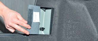
- Another mounting block, which is located near the left foot of the front passenger. To gain access to the fuses and relays, unscrew several screws with a Phillips screwdriver.
Below is a description of each fuse and relay block in order.
Repair and replacement of individual elements
Wear of headlight elements, physical damage or short circuit are only a small part of the reasons why the luminous flux is lost or noticeably weaker.
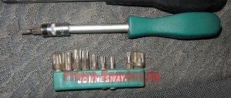
In this case, you need a “10” key and a Phillips screwdriver. To begin, carefully remove the negative terminal from the battery and the front bumper. Only after this Lada Priora is ready for work:
- release the lock;
- disconnect the bundle of wires;
- Unscrew the screw for the side mounting of the headlight on the Priora;
- remove 4 clips;
- Unscrew the housing fastening bolts.
Installation of new lighting elements is carried out in the reverse order. If problems arise with the rear lights, then their dismantling on the Priora is carried out in a similar way. In some cases, the functionality of the lighting element can be restored by replacing one of the parts. For example, if the headlight burns dimly, then the bulb needs to be replaced.
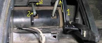
To complete this task you will need an industrial hair dryer. It works at a distance of 2-4 cm from the surface of the headlight. The duration of thermal exposure is 30 seconds. After the industrial hair dryer is turned on, it is necessary to act in a circumferential manner on the entire surface of the top cover. The result of the work done will be melted sealant. It does not cause technical malfunctions, while allowing you to carefully remove the lighting element on the Priora.
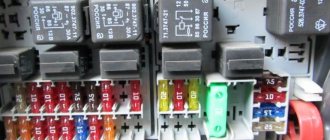
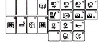
Priora fuse box diagram
| Fuse no. | Current strength, A | "Standard" and "Norm" | “Norma” with air conditioning and “luxury” |
| F1 | 25 | Engine cooling radiator fan | Reserve |
| F2 | 25 | Heated rear window | Mounting block, rear window heating relay (contacts). Electrical package controller, contact “10” of XP2 block. Rear window heating element. |
| F3 | 10 | Right headlight, high beam | Right headlight, high beam lamp. Instrument cluster, headlight high beam indicator. |
| F4 | 10 | Left headlight, high beam | |
| F5 | 10 | Sound signal | Mounting block, horn relay. Sound signal. |
| F6 | 7.5 | Left headlight, low beam | |
| F7 | 7.5 | Right headlight, low beam | |
| F8 | 10 | Alarm signal | Mounting block, alarm relay. Alarm sound. |
| F9 | 25 | Priora heater fuse | Reserve |
| F10 | 7.5/10* | Interior lighting, instrument panels, brake light | Instrument cluster, pin “20”. Brake light switch. Brake light bulbs. Interior lighting unit. Interior lighting. The door sill light on the right front door. Additional brake signal. |
| F11 | 10/20* | Wiper | Mounting block, high speed windshield wiper relay. Switch for cleaners and washers, contact “53a”. Wiper and washer switch, contact “53ah”. Heated rear window switch. Mounting block, rear window heating relay (winding). Windshield wiper motor. Rear window wiper motor (2171,2172). Windshield washer motor. Rear window washer motor (2171,2172). Airbag control unit, pin “25”. |
| F12 | 20/10* | Terminal 15 devices | Instrument cluster, pin “21”. Electrical package controller, contact “9” of block X2. Electromechanical power steering control unit, contact “1” of block X2. Reversing light switch. Reversing lamps. Parking system control unit, contacts “11” and “14”. |
| F13 | 15 | Cigarette lighter fuse Priora | |
| F14 | 5 | Left headlight, parking light, license plate light, trunk light | Side light lamps (left side) Instrument cluster, main light indicator License plate lights Trunk light Electrical package controller, pin “12” of block X2 |
| F15 | 5 | Right headlight, parking light | Side light lamps (right side) Glove compartment lamp |
| F16 | 10 | Terminal 15 ABS | Hydraulic unit, contact "18" |
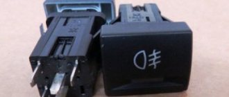
| F17 | 10 | Left fog lamp | |
| F18 | 10 | Right fog lamp | |
| F19 | 15 | Seat heating | Seat heating switch, contact "1" Front seat heaters |
| F20 | 5/10* | Immobilizer control unit | Recirculation switch (switch on) Mounting block, relay for low beam headlights and parking lights (automatic lighting control system) Heater electric fan relay Automatic lighting control switch Windshield wiper and external lighting control unit, contacts “3”, “11” Automatic climate control system controller installation, pin “1” Automatic window cleaning system sensor (rain sensor), pin “1” |
| F21 | 7.5/5* | Rear fog lights | Light switch, contact "30" Diagnostic block, contact "16" Clock Automatic climate control system controller, contact "14" |
| F22 | -/20* | Reserve | Windshield wiper motor (automatic) Mounting block, windshield wiper relay and windshield wiper high speed relay, (contacts) |
| F23 | -/7.5* | Reserve | Windshield wipers and external lighting control unit, pin “20” |
| F24-F30 | Reserve | ||
| F31 | 30 | Electrical package control unit | Electrical package controller, terminal “2” of block X1 Electrical package controller, terminal “3” of block X1 Driver’s door module, pin “6” Threshold light of the left front door |
| F32 | Reserve | ||
Lost low and high beam on Priora
If you adjust the headlights correctly , Priora will be safe to use. That is why, when inspecting the technical condition of a vehicle, increased attention is paid to this aspect. The traffic police officers do not lose sight of the quality of the lighting elements. Switched on and properly working low beam headlights improve visibility of the road.
Checking and adjusting the operation of the mechanism
Regular preventative examinations will help you avoid sudden breakdowns. According to the manufacturer's recommendations, these are carried out at least once every 3 months. Unscheduled, you will need to look under the hood if the Priora's light has become dim. Regardless of the reason, a key at “6” is required for operation.
The car owner must check the air pressure in the tires. Even a slight deviation from the norm will negatively affect the efficiency of lighting devices. After this, the vehicle is installed on the most level surface of the garage. LADA Priora is placed at a distance of 5 m from a smooth wall. The further procedure is as follows:
- install a load weighing 70-75 kg on the driver’s seat;
- place a small white screen against the wall;
- draw vertical mowing lines on it;
Direct adjustment is carried out in the vertical and horizontal plane. In order to adjust the position of the light spot as accurately as possible, you should first turn on the low beam. The setting is made for each headlight separately. In order to comply with technical recommendations, when adjusting one of the headlights, the second one must be covered with material that does not transmit light .
If you don’t have one at hand, then you just need to turn off the power. Only after this does the transition to high beam adjustment take place. The lighting adjustment process ends with a mandatory check. A vehicle rolls out of a garage onto the street at night.
The high turns on , and then the low beam. A visual inspection is carried out. If asymmetry of the light spots is noted, then the adjustment is made again. In some cases it is necessary to visit a service station.
Sources:
https://otmetka68.ru/istochniki-sveta/kakoj-tsokol-v-farah-priora.html https://chevroletcars.ru/info/ksenon-v-dalnij-svet-priora/ https://www.zr .ru/content/articles/836507-lampy-primenyaemye-v-avtomobile-lada-priora/ https://spb-bitauto.ru/raznoe/priora-ne-rabotaet-blizhnij-svet-dalnij-rabotaet-ne-gorit -blizhnij-svet-na-lade-priora-prichiny-kakoj-predoxranitel.html
Location of Priora fuses under the hood
- F1 (30 A) – power supply fuse for the electronic engine control system (ECM);
- F2 (60 A) – fuse for the power supply circuit of the engine cooling system fan (power circuit), additional relay (ignition relay), rear window heating, electrical package controller;
- F3 (60 A) – fuse for the power supply circuit of the electric fan of the engine cooling system (relay control circuit), sound signal, alarm signal, ignition switch, instrument cluster, interior lighting, brake light, cigarette lighter;
- F4, F6 (60 A) – generator power circuit fuses;
- F5 (50 A) – fuse for the power supply circuit of the electromechanical power steering
Relay and fuse box for Halla air conditioner
- right electric fan power supply fuse (30 A);
- fuse for the power supply circuit of the left electric fan (30 A).
- right electric fan relay;
- additional relay (sequential activation of left and right electric fans);
- left electric fan relay;
- heater fan power supply fuse (40 A);
- compressor power supply fuse (15 A);
- heater fan relay;
- compressor relay.
Panasonic air conditioner relay and fuse box
- Heater fan maximum speed
- Right fan
- Fan sequential relay (low speed)
- Left fan
- Left fan fuse (low speed)
- Right fan
- Heater fan
- Compressor
- Heater fan
- Compressor
Additional mounting block Priora
- F1 (15 A) – main relay and starter interlock circuit fuse;
- F2 (7.5 A) – fuse for the power supply circuit of the ECU (controller);
- F3 (15 A) – Priora fuel pump fuse;
- K1 – main relay;
- K2 is the place where the Priora fuel pump relay is located.
Attention!
The relay and fuse diagram may differ depending on the configuration and production date of the vehicle. Current diagrams of the mounting block are presented in the operating manual for the date of manufacture of the vehicle (download from the official website).
Let us remind you that on our website you can find detailed instructions for repairing the Lada Priora with your own hands.
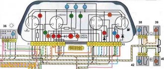
To ensure the normal operation of all devices and instruments, each car is equipped with an electrical system. Modern cars have a more complex electrical circuit, since they are equipped with many devices designed for comfortable driving. From this material you will learn what the Priora electrical circuit is and how to determine a malfunction in its operation with your own hands.
Lamps used in the Lada Priora car
For reasons of safety of drivers, passengers and pedestrians, the Traffic Rules and the Technical Regulations on the Safety of Wheeled Vehicles prohibit the operation of vehicles whose external lighting devices do not meet the design requirements of the vehicle. After all, on the one hand, it is necessary that the car is clearly visible on the road, and on the other hand, it is dangerous to blind other drivers or pedestrians with too bright or incorrectly adjusted headlights. Working brake lights will allow drivers moving behind you to keep a safe distance. There are many such nuances, and everyone can save not only money and nerves, but often also health.
Features of electrical equipment
The electrical circuit of a Lada Priora car includes several main elements - front and rear blocks, control panel blocks, as well as engine control systems. All these elements are connected to each other by special plugs located on the left under the center console, as well as above the mounting block. Only the control panel and engine control system harness is located in the heating system shaft, on the driver’s side. It should also be noted that the rear block and the device are connected to the control device via an electrical package, which is located inside the car.
The main systems that the electrical circuit includes:
- heating unit, stove;
- optics, including main headlights, dimensions, fog lights, turn signals;
- windshield and rear window cleaning system, if provided for by the vehicle design;
- car central locking;
- electric windows.
Diagnostic tester with test lamp for checking electrical circuits
Possible wiring faults
What malfunctions in the operation of the on-board network may a car owner encounter:
- The device itself does not work. For example, the rear window heating system or the electric side mirror controller refuses to function. There is a possibility that the reason lies in the device itself or the fuse that is responsible for its operation.
- Short circuit in the electrical network. As stated above, a short circuit problem usually manifests itself as a result of insulation failure in one area or another. To prevent this, wires should be laid in places where there are no moving elements.
- Broken wiring. This malfunction is typical for many Russian-made cars. To prevent a breakdown, consider the recommendations described in the paragraph above.
- Failure of the safety element. If you notice that malfunctions have begun to appear in the operation of certain devices, then first you should open the mounting block and check the integrity of the fuse itself. There is a possibility that this is where the problem lies. Typically, safety devices break due to too high voltage in the on-board network. If the reason really lies in overvoltage, then first you need to eliminate the problem itself, and only then change the fuses.
- Lack of contact. In this case, a section of the circuit may be intact, but there will be no contact. Most likely, in this case, the problem lies in the fact that the wire has come off a little or the contact at its end has oxidized. In this case, the contact is cleaned using a brush or sandpaper, after which the wire is reconnected.
Why the headlights don't light up - reasons
The most common reason for headlights not working is a burnt out light bulb. Its service life is indicated in hours on the packaging. For a low beam bulb, this limit can be 400 hours of operation. The second extremely possible reason could be a wiring malfunction due to water leakage, or the wire simply frayed. This problem is already more serious, because you will have to fuss with it much longer than with a regular replacement of consumables.
Often, car enthusiasts are too lazy to change light bulbs, driving out onto the road in “one-eyed” cars. This is very unsafe - it is recommended that immediately after a malfunction is noticed, you go for a spare part to replace a new lamp.
Replacing the lamp in the high beam optics on a LADA Priora (VAZ 2170) car, although not difficult, is quite a sensitive matter. With the right approach, it is quite accessible to anyone. Therefore, let’s consider what base is used for the light bulbs in the headlights of this car, which models and manufacturers of light sources are most popular on the market, what are the differences and features on the pre-restyling and restyled versions, as well as what basic steps the step-by-step instructions for updating a burnt-out light bulb include.
How to determine the malfunction?
If you notice that there are problems with the wiring of the Priora or one of the devices is not functioning, then you can diagnose the voltage using a multimeter. In particular, you will need to check whether there is voltage in the power circuit connecting the failed device to other devices.
How to do it correctly:
- First you need to switch the tester to voltmeter mode.
- Next, one tester probe is connected to the battery or vehicle body, depending on where the device being diagnosed is located.
- The second probe of the device must be connected to the supply cable in the circuit being diagnosed, but before this the terminals from the device must be removed.
- If, during diagnostics, readings appear on the tester screen, this indicates that there is voltage in the circuit, and accordingly, the tested wires are in good condition.
- Similar actions are performed with the remaining wires that require checking. If you eventually find a point where there is no voltage, then this indicates that the source of the breakdown is located in this section of the circuit. The only thing left to do is just find the cause and get rid of it (the author of the video is the PRO.Garage channel).
If there is no voltage in the circuit at all, you can diagnose a possible short circuit.
To do this, follow these steps:
- First, you need to remove the part that is responsible for the circuit being diagnosed from the fuse block.
- As in the previous case, the multimeter should be activated in voltmeter mode.
- One tester probe should be connected to the safety element connection outputs. Make sure that all other equipment and devices in this circuit are not connected.
- Then move the wire itself a little - if at this moment indicators appear on the display, this indicates that the wire is shorting somewhere. The problem must be solved as quickly as possible - qualified electricians say that in principle it is not worth bringing the electrical circuit to such a state.
A short circuit usually appears in that section of the circuit where the insulation has worn off. This procedure can be carried out with any component of the electrical circuit, as well as with switches. If the diagnostics showed the absence of a short circuit, then there is another test option.
In particular, we are talking about searching for a possible break in the electrical network, the procedure is performed as follows:
- First you need to turn off the power to the on-board network or just one area that you want to check. To do this, either disconnect the terminals from the battery, or simply remove the safety device from its mounting location.
- Now we proceed directly to the test - the tester probes should be connected to the two ends of the electrical circuit section.
- Next, one of the probes should be connected to the car body; you need mass.
- If, at the time of connection, indicators begin to appear on the tester’s display, this indicates that there are no breaks in this section of the electrical circuit. If there are no changes, then we can say with confidence that there is a break in the wiring.