Checking the camshaft sensor (DPRV) allows you not only to verify its performance, but also to make sure that in engines with phased (sequential) injection, fuel is supplied in exactly the required sequence. Another name for the device is a phase sensor (it is often used by owners of domestic VAZs). The test can be performed using a multimeter in voltmeter mode and/or an oscilloscope. Checking the camshaft position sensor is simple in nature, and even a novice car enthusiast can handle it.
What is a camshaft sensor
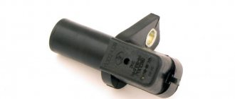
Before moving on to the question of checking the camshaft position sensor, you need to find out what kind of device it is, what it is needed for and on what principle it works. This will help clarify the details of the audit in the future.
A camshaft sensor is a device that records the angular position of a specified shaft at a specific point in time. The information obtained with its help is transmitted to the electronic engine control unit (ECU), and on its basis this control element issues commands for fuel injection and ignition of the air-fuel mixture in each cylinder at a specific point in time.
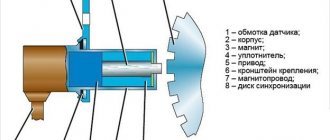
The operation of the camshaft position sensor is based on the Hall effect. So, directly on the camshaft there is a metal tooth, which, when the shaft rotates, changes the magnetic field in a nearby sensor. This tooth is called rapper. The sensor detects a change in the magnetic field, which is converted into a low voltage electrical signal. This signal is sent to the electronic control unit.
In fact, the camshaft position sensor only registers one position, corresponding to the position of the piston of the first cylinder at top dead center. Next, phased fuel injection is performed in the firing sequence of the cylinders. Typically this is a 1-3-4-2 system.
If the camshaft sensor fails (the electronic control unit receives incorrect information from it or does not receive it at all), then it is programmed to switch to emergency mode. It involves the use of pairwise-parallel (group) fuel supply to the engine. This leads to two negative consequences:
- A slight loss of engine power, especially when driving in critical modes (acceleration, driving under load).
- Increase in fuel consumption by approximately 10...20% (depending on engine power, its design features, as well as operating conditions).
As for diesel engines, camshaft position sensors are designed similarly, but there is one difference. It lies in the fact that the sensor records the position of not only the first cylinder, but all of them. This is done due to the fact that the drive disk has a separate tooth for each cylinder.
Thus, if a sensor fails, it makes sense to diagnose it as quickly as possible and, if necessary, replace it.
Camshaft sensor on a diesel engine
How to check the camshaft sensor! 2 ways
1st way to check with a multimeter. 2nd way to check with a metal object.
Camshaft sensor. Lifehack. How to check it yourself?!
Nissan camshaft sensor error
primera p12.
On a diesel engine, the camshaft position sensor works differently compared to its gasoline counterpart. Pulses from the sensor record the position of the piston at TDC not in the 1st cylinder, but in all. This solution makes it possible to achieve the most accurate determination of the position of the camshaft in relation to the crankshaft. In a diesel engine, the DPRV is responsible for the starting efficiency and stability of the power unit of this type in different operating modes.
In a diesel engine, certain design changes are present on the master disk. The teeth on this element are made for each cylinder of the internal combustion engine and are installed at a certain distance. As an example, consider a diesel engine that has 4 cylinders. In such a motor, the drive disk has 7 teeth (4 main teeth, located at an angle of 90 degrees relative to each other). There are also an additional 3 teeth to help identify the cylinders individually. These teeth are located at a certain distance from the main ones in order to accurately determine the position of the piston in each individual cylinder.
Signs of DPRV failure
There are several typical signs that indicate that the camshaft position sensor has failed. It is immediately necessary to clarify that the symptoms listed below may indicate completely different malfunctions. Therefore, it makes sense to perform additional diagnostics. So, signs of a DPRV breakdown:
- Problems with starting the engine, under any conditions - “cold”, “hot” and in other modes. This usually results in having to crank the starter longer.
- Unstable engine operation, “floating” operating and idle engine speeds.
- “Dips” in the movement of the car; when you press the accelerator pedal, it does not respond immediately, the dynamic characteristics of the car are lost (it accelerates poorly, does not pull, especially when loaded and when moving uphill).
- When the accelerator pedal is released, the engine stalls.
- Increased fuel consumption (by 10...20%).
- The Check Engine warning light on the instrument panel activates. It is necessary to perform additional diagnostics using an electronic scanner (for example, an ELM 327 device or its equivalent). In this case, typical errors regarding the operation of the sensor are numbers P0340, P0342, P0343.
In fact, the camshaft position sensor is a fairly simple and reliable device, so it rarely fails. More often, its wiring is damaged - the wires fray, the insulation on them is damaged, the so-called “chip”, the place where the sensor is connected to the car circuit, fails.
However, for cars that run on gasoline, the problems described above are not so clearly expressed. But a failed camshaft position sensor will cause many problems for owners of cars equipped with gas equipment, in particular the fourth generation. The malfunctions and problems described above can appear on such machines “in all their glory.” Therefore, owners of cars equipped with HBO are strongly recommended to diagnose and replace the sensor as quickly as possible if it is suspected of being faulty.
How do you know if the camshaft sensor has stopped working?
But here’s what matters and what are the most tangible and therefore important signs of problems with the CMP sensor (“CMP”, in the English manner): the yellow indicator on the dashboard comes on, the well-known “Check engine”, engine failure to start, loss of traction/ power, the engine may begin to stall. These are only the most noticeable signs associated with the fact that one of the possible culprits for the inconsistent operation of the car engine is the CMP sensor. Read more about the types of malfunctions and nuances of the operation of the camshaft sensor here: Signs of a malfunctioning camshaft sensor
As soon as you encounter such problems, the second thing you need to do is make sure that it is this particular sensor that is being naughty, since, we repeat, its failure is a fairly rare occurrence, and the symptoms in themselves do not mean anything, there can be a dozen reasons, and they may be completely unrelated to the CMP sensor. For example, cravings have disappeared. It is possible that the hydraulically controlled clutch, the so-called phase shifter, on the intake camshaft has failed. Is the engine running rough? It's quite possible it's the spark plugs. And so on.
The first thing you (or the car service workers) should do is read the error code that is recorded in the car’s on-board computer. There can be 5 main errors, each of them is numbered from P0340 CMP to P0344 CMP, and under each of these numbers there will be a different reason for the failure of the sensor to operate normally, usually associated with an incorrect signal coming from the DPRV.
If, after you have connected to the OBD 2 diagnostic connector, one of the above errors appears on the screen, be sure that the problem is related to this sensor. Congratulations, you're in luck! How is it repaired?
Location of the DPRV on the engine
To check the camshaft position sensor, you need to know where it is located. As a rule, on eight-valve engines the DPRV is usually mounted at the end of the cylinder head. On sixteen-valve engines it is also mounted on the cylinder head, usually in close proximity to the first cylinder.
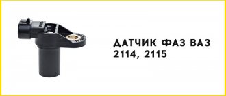
As for popular domestic VAZ cars, their owners call such units phase sensors. Their location in these motors is similar. So, on eight-valve engines, the sensor is located on the left side of the cylinder head (when viewed in the direction of travel of the car). On sixteen-valve engines - on the right front part of the engine. In the latter case, the sensor is not directly visible visually; its location can only be assessed by the signal and power wires suitable for it. The VAZ 2114 phase sensor is fixed in close proximity to the air filter, near the cylinder head.
What affects the serviceability and operation of the DPRV
The main factors that affect the operation of the sensor are temperature changes, shaking and metal dust. Therefore, it is necessary to replace the sensor every 100 thousand kilometers. This will avoid unexpected breakdown. When the engine is turned on, the temperature in the sensor area corresponds to the air temperature. As the motor heats up, the temperature of the sensor also increases. If the power supply or ignition systems are not adjusted, the engine runs intermittently, and the sensor is affected by stronger vibrations than designed. The engine has a lot of rubbing metal parts, the movement of which leads to the appearance of dust. If the lubrication system is not working properly, or the engine mounts are faulty, then more metal dust appears than usual. Some of it settles on the magnetic surface of the sensor, negatively affecting its operation.
Methods for checking the camshaft sensor
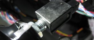
Before testing the sensor using a multimeter or other electronic tools, you must check its mechanical integrity. In particular, it is installed in a housing with an O-ring, ensuring its secure fastening. We need to check its condition. It would also be useful to check the integrity of the sensor body, whether there are cracks or other damage on it. It is advisable to check the drive disk to see if the teeth are damaged or if there are metal shavings on the sensor body or nearby.
On the Internet you can find information that supposedly the DPRV can be determined to work by simply checking its magnetic properties. In particular, bring a small metal part to its end (the working sensitive part), which should “stick” to the sensor. In fact, this is not the case , and a non-working DPRV may or may not have magnetic properties. Accordingly, verification must be performed using other methods.
There are two main ways to test the camshaft position sensor - using an electronic multimeter and using an oscilloscope. The first method is simpler and faster, but the second is more accurate and provides more diagnostic information.
Checking the camshaft sensor with a multimeter
To check the DPRV, dismantling is necessary. This is not difficult to do; you just need to disconnect the contact group of wires from it and unscrew the fastening bolt. You will also need a small metal object (ferrous metal so that it is magnetic) to test.
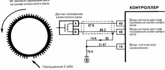
Connection diagram for checking phase sensor 21110-3706040
Connection diagram for checking phase sensor 21120-3706040
The algorithm for checking the sensor with a multimeter is as follows:
- Take a multimeter and switch it to the DC voltage measurement mode in the range up to 20 V (depending on the specific multimeter model).
- Disconnect the “chip” from the sensor by unclipping the latch.
- Remove the sensor from its mounting location.
- On the “chip” of the sensor 21110-3706040 of a VAZ car (and on many others), contact “A” corresponds to ground, contact “C” is the positive wire, comes from the control relay, contact “B” is the signal wire (middle). For sensor chip 21120-3706040, contact “A” corresponds to ground, contact “B” is the positive wire from the control relay, contact “C” is the signal wire.
- Check the presence of power on the chips. To do this, you need to turn on the ignition on the car (but do not start the engine) and do this with a multimeter. If there is no power to the chips, then you need to look for the reason. This could be faulty wiring (insulation damage, broken wires), failure of the control relay, or a glitch in the electronic control system (ECU).
- Next, you need to connect the sensors for testing according to the diagrams shown in the figure.
- Apply a voltage of 13.5±0.5V to the sensor (although less is allowed, for example, 12...12.5 Volts from the battery).
- If, when power is applied to the sensor, the voltmeter detects a lack of voltage on the sensor, then this indicates either a breakdown of the sensor itself, the test can be completed and you can prepare to replace the sensor with a new one.
- Measure the voltage between the positive and signal contacts. It must be equal to at least 90% of the supply voltage (that is, if the supply voltage is 12 Volts, then the voltage at the signal contact must be at least 10.8 Volts).
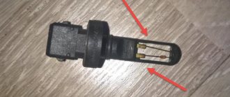
- Bring a metal object prepared in advance to the end of the sensor (its signal part). Re-measure the voltage at the signal contact. It should be no more than 0.4 Volts. Remove the plate - the voltage value should be restored to 90.100% of the supply. If there are any deviations during the verification process, it means that the sensor has failed and must be replaced.
Self check
A common malfunction of an internal combustion engine with electronic injection is a malfunction of the camshaft position sensor. The list of signs indicating problems with the sensor includes:
- difficult starting;
- unstable engine operation;
- the engine shakes and runs intermittently;
- “check” light may light up on the instrument panel;
- The first step is to locate the DPRV mounting socket, which is installed in the cylinder head area. You must find a special O-ring at the installation site. This ring must be inspected, since damage to its integrity and other deformations can lead to sensor malfunctions.
- Additionally, you will need to inspect the sensor housing itself, as well as the gear rotor. The presence of damage or the presence of metal shavings also indicates a sensor failure.
- Next you need to examine the connector itself. Such a connector must have contacts: positive contact, negative ground, contact for signal transmission.
- Then you need to turn on the ignition, after which a voltmeter is used to measure the voltage at the positive contact of the camshaft position sensor. The tester ground must be connected to the engine ground. This voltage measurement should be similar to the voltage at the battery terminals. If there are deviations in the voltage readings compared to the power supply, we can conclude that there is a malfunction in the electrical power supply circuit of the camshaft position sensor.
- The voltage at the sensor ground is measured in a similar way. The voltage at the specified contact should be zero.
- Then you need to connect the positive and negative wires of the sensor. The middle contact of the sensor is connected through the tester. It turns out that one voltmeter probe is applied to the signal terminal of the sensor, and the other is powered to the input of the control system. To solve this problem, it is not uncommon for the signal wire to be cut and the multimeter probe to be applied to the exposed wires.
- The engine is then cranked by the starter. The working sensor will show voltage, which can range from 0.4 to 5 volts. Deviations from the specified values indicate the need to replace the DPRV.
Replacing the RV position sensor
If during the inspection it turns out that the camshaft position sensor itself has failed, then it must be replaced. As a rule, these units are non-repairable, since their body is sealed and cannot be disassembled. The sensor is inexpensive, and the replacement procedure is simple, and even a novice car enthusiast can handle it.
The sensor replacement algorithm is as follows:
- With the engine not running, disconnect the negative terminal from the battery.
- Disconnect the “chip” from the camshaft position sensor (as when checking).
- Depending on the vehicle model, it is necessary to remove parts that prevent access to the sensor. For example, on modern cars like the Lada Vesta, it is necessary to remove the bracket for auxiliary units.
- Using a wrench, unscrew one or two mounting bolts, depending on the type of fastening. The size of the wrench can be different, usually for VAZs it is a 10 mm wrench.
- After dismantling the mount, you must similarly remove the sensor from its seat.
- Installing a new sensor is performed in reverse order.
- Connect the negative terminal to the battery.
When purchasing a new camshaft position sensor, you need to pay attention to the condition of its O-ring. It is usually sold separately. When changing the sensor, it is advisable to also change the O-ring, since over time it wears out and loses its elasticity. You can use an old ring only in case of emergency, when it is not possible to buy a new one.
Conclusion
The camshaft position sensor is a simple but important device in the engine, and the normal functioning of the engine depends on its operation. Therefore, when identifying signs of its failure, it is advisable to carry out the appropriate diagnostic procedures as quickly as possible. They are simple, and even a novice car owner with no experience can handle them. The same goes for replacing it. The price of a phase sensor for VAZ cars as of winter 2019 is about 400 rubles.
I decided to share my experience about these two wonderful sensors! My experience
I have experience, because...
I played with them for a whole week, re-read all possible and impossible articles, rechecked several sensors, etc. Information for engines with the brains of Siemens MS 40-40.1
So, in the future:
DPKV
crankshaft position sensor DPPV
- camshaft position sensor
A
little theory:
Crankshaft position sensor (CPKV) (SKR) (Pulse sensor, Hall sensor, Ignition distributor pulse sensor) .
Symptoms of the malfunction: - unstable engine speed at idle - spontaneous increase or decrease in engine speed - engine stoppage - impossibility of starting the engine/difficulty starting the engine - decrease in engine power - detonation occurs under dynamic loads - misfiring If it malfunctions, the fuel pump will not turn on , no injectors opening, no spark. If any of this is present, then most likely it is not the reason.
Note: If a BMW E34 has DME (brains) from Siemens, then in the event of a malfunction of the DPKV, the car will start and operate (possibly not quite stable), taking readings from the DPKV. It is not possible to check the sensor with a tester (measuring the resistance).
If the DPKV is faulty, it is not a fact that there will be no spark, no fuel supply, etc. It may work, but not very well (wires are exposed). There will be a spark and there will be fuel, but the whole thing will be poorly synchronized.
Camshaft position (phase) sensor (DPRV, Pulse camshaft sensor).
Symptoms of the malfunction: - fuel consumption - malfunctions of the self-diagnosis system - the exhaust is dirtier
Now my observations:
These sensors are reliable in principle... BUT over time, the wire winding becomes tanned and begins to crumble... even if the wires do not touch, they no longer have a “screen” that keeps the signal in the wire itself, preventing it from being lost. The main one for engine operation, of course, is DPKV! Without it, the machine, even if it works, will be very unstable, and popping noises are possible. The ignition will be slightly incorrect. This sensor synchronizes the fuel supply and the spark so that they are supplied simultaneously.
The DPRV determines which cylinder receives both spark and fuel.
Sensors WITHOUT a protruding magnet are suitable for Siemens MS40 and MS40.1 brains. DPKV - 12 14 1 730 027 DPRV - 12 14 1 703 221
How to check sensors?
You can’t just check them with a multimeter
Siemens brains You need an oscilloscope that measures phase shifts in frequencies... here is an article
about this, as well as about resuscitation of the sensor... But you can at least approximately check the resistance to understand whether the wires are shorted somewhere along the way or not... Between the 1st and 2nd the leg on the “male” of the sensor should be about 13 ohms, between the 2nd and 3rd - about 3 ohms. (some sensors have leg numbers written on them, others don’t) This way you will know that the sensor itself is not closed.
How to check the wire from the sensor to the brains?
We measured the resistance of the sensor between the 1st and 2nd legs, 13 ohms there.
Hooray. We connect it to the “mother” of this sensor under the intake manifold. Let's go to the brains (I think everyone knows where the brains are on their machine). We open the protective plastic cover on the long “male”, which is inserted into the brains. There we see a bunch of wires in 3 rows. If you need a full pinout, look here
. In the diagram we find DPKV and DPRV
My advice to those who have not encountered these sensors:
Even if the car is working normally... I still advise you to check these two sensors. a malfunction of the DPKV is generally difficult to notice, and the DPKV can ruin your nerves, as always, at the wrong time.
Every modern car has a camshaft position sensor. It is a very important part of any vehicle as it helps ensure that the engine runs properly. The camshaft position sensor is built next to the engine just under the hood. Typically, different car manufacturers and brands have their own unique location for mounting the sensor near the engine. You can find it either at the back of the cylinder head or near the engine.
Lada Priora Hatchback BLACK -STAR (former) › Logbook › replacing the camshaft sensor
A faulty phase sensor (PF) can only be determined using a diagnostic tool. If the sensor fails, the engine characteristics do not change in any way, except for a slightly increased fuel consumption (0.5 l), which is easily hidden behind the driving style. Another symptom is a delay in starting the engine for 2 seconds due to waiting for a signal from the sensor. Afterwards the ECU will switch to pairwise parallel injection.
If, due to this malfunction, the car stalls and idles unstably, and also becomes “dull” during acceleration, then it is worth checking whether the toothed pulley on the crankshaft (which goes to drive the generator and other systems) has turned. To check, it is necessary to set the first cylinder to top dead center (TDC). The crankshaft position sensor should look at the beginning of the 20th tooth from the two missing ones.
If everything is in order with the pulley and operation, then you need to reset the error on the ECU and see under what conditions it appears again. If an error does not occur when the engine is idling, all connections and wires must be checked. This is done by wiggling the terminal and wiring harness. If an error appears during this operation, then you need to look for a bad contact, it has nothing to do with the sensor.
If the error occurs 15 seconds after the reset during smooth operation, then you can safely change the sensor. For reliability, it can be checked (a test diagram is available on the Internet), but the price of a new sensor is about 200 rubles - for this money it is easier to buy a known good one, and, even if it turns out not to be the problem, have a spare one.
So, we are convinced that the problem is in the sensor and we will change it.
To replace the phase sensor on cars of the Priora, Kalina and Grant families with a 16-valve engine, we will need:
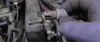
“10” wrench (preferably a “10” head) “5” hexagon “17” wrench Phase sensor for a 16-valve VAZ 1 engine. The sensor is installed on the front side of the engine (radiator side) next to the intake camshaft pulley shaft It is not visible from above. We determine the position by the wiring harness suitable for this location.
Determining the position of the phase sensor
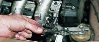
2. Disconnect the terminal. Using a 10mm wrench, unscrew the two bolts. Unscrew carefully, as they tend to “run away” under the car and into the generator along with the washers.
3. Remove the sensor and inspect it. In this case, mechanical damage was found on it from the camshaft pulley. It is necessary to remove the protective plastic casing and check the condition of the entire mechanism. If the DF has no traces of contact with the pulley, then simply replace the sensor with a new one and reassemble it in the reverse order.
Inspecting the removed sensor
4. I’ll immediately make a reservation that in this case there was a problem with the generator pulley (the gear ring of the crankshaft sensor turned). The crankshaft sensor determined the TDC position with an error, the engine vibrated strongly, which led to the breakdown of the phase sensor. And only then did the error light up on the instrument panel.
5. Unscrew the screws securing the casing using a 5mm hexagon. They are located at the top and along the edges, one in the center below the lip and one on the left edge of the casing below. We take out the screws along with the casing. We inspect the condition of the timing belt (in the photo below, for clarity, the cover has already been removed).
6. Set the first cylinder to top dead center. To do this, either put the car in 4th gear and drive, or turn the crankshaft or camshaft bolt with a key. The marks on the camshaft pulleys should fall under the slots on the plastic boot (indicated by arrows).
Setting the first cylinder to top dead center
7. Both marks should be at the top. To check the correct alignment of the crankshaft, there is a window in the gearbox, but it is made for an 8-valve engine, and in the 2112 engine it is very difficult to navigate through it. It’s easier to check by the ring gear on the auxiliary pulley. The crankshaft sensor (CSC) should look at the beginning of the 20th tooth after the gap (the arrow on the right shows the gap, the arrow on the left indicates the CSC):
What is a camshaft position sensor
The camshaft position sensor is also called the cylinder sensor or camshaft sensor. In sequential fuel injection systems, the electronic control unit must determine which cylinder should be injected next. This information affects engine operation and comes from the DPRV. As the engine rotates, the DPRV sends a signal to the on-board computer whenever a particular cylinder is at top dead center (TDC). Thus, the duration of pulse injection is estimated, for which the camshaft sensor is responsible.
In simultaneous fuel injection systems, the on-board computer is not used to determine the cylinder and injection order, since this is not necessary for the operation of the system. When a signal is received from the crankshaft or distributor, the exact cylinder is determined by recognizing the mechanical positions of the crankshaft, camshaft and valves.
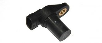
Types of sensors used
The most popular are 2 types of DPRV, which look almost the same and differ slightly in design:
An inductive sensor is needed to register the cylinder and can be located inside the camshaft. Therefore, a device with a magnet is mounted near it. Each time a magnet passes through the DPRV, its magnetic field changes and the resulting pulse is sent to the on-board computer for subsequent processing.
The Hall sensor may be located inside the camshaft. A screen with a socket and a magnet is installed on the shaft. When the screen passes between the magnet and the hall sensor, the DPRV turns on and off. While the socket is in front of the DPRV, the voltage returns to the amplifier through the third signal cable. As long as there is a solid sector of the screen in front of the sensor, the feedback voltage is interrupted as the magnetic field disappears.
What is a camshaft sensor and what is it used for?
It is necessary to respond in a timely manner to changes during operation. And they will definitely be there. The camshaft adjustment to achieve the parameters you need will also occur during engine operation. And to help us there is such a device as a Hall sensor (camshaft position sensor or valve timing sensor).
The design features of different types of engines may require different placement of the camshaft sensor on the engine. But the principle of its operation remains unchanged. In addition, the camshaft sensor is functionally connected to the crankshaft speed sensor.
The operating principle of the camshaft sensor is based on the Hall effect - a change in voltage in a semiconductor at the moment of a change in the magnetic field crossing it. There is a magnet in the sensor itself.
The metal tooth (benchmark) closes the magnetic gap and changes the magnetic field. The reference point itself is located on the camshaft gear (alternatively, on the master disk located on the camshaft).
Where is the sensor located
The location of the DPRV varies depending on the make of the car. In most cases, you can find it in the following places:
- near the cylinder head;
- near the wiring connectors on the front of the motor;
- near the toothed belt mount;
- on the rear side of the cylinder head;
- special compartment under the hood;
- inside the cylinder head.
First, consult your vehicle's manufacturer's repair manual. This contains all the necessary information.
Working principle of the camshaft position sensor
The task of the DPRV is to work with the crankshaft sensor to determine the exact position of its drive. Thanks to the combination of both sensor signals, the engine control unit knows when the first cylinder is at top dead center.
This information is needed for 3 purposes:
- To start fuel delivery during sequential injection.
- To activate the solenoid valve signal for the pump injection system.
- To control cylinder detonation.
The DPRV operates in accordance with the Hall principle. It scans the ring gear on the camshaft. Rotation of the ring gear changes the Hall voltage IC in the DPRV housing. This voltage change is transmitted to the control unit and evaluated there in order to set the required data.
Problems that a faulty camshaft sensor can create
The camshaft's job is to control the consumption of gasoline and the emission of vapors from the exhaust system. Compensation vanes are installed on the camshaft, which control the exhaust and intake valves. The timing belt and chain connect the camshaft to the crankshaft. The vehicle's engine control unit monitors the rotating position of the camshaft using a component called a "camshaft position sensor." Based on the information transmitted by the DPRV, the engine control unit will determine how much fuel should be introduced into the combustion chamber. There are many symptoms of a bad camshaft sensor in your car.
Ignition problems – The mixture of air and fuel in an internal combustion engine requires a spark to ignite. In some vehicles, if the DPRV fails, there will be no spark, which is the first sign of a DPRV malfunction. If you can't create a spark, then you can't start the engine. Unfortunately, it is quite difficult to determine the source of the malfunction, especially if it is a DPRV. But don't be surprised that it might be him.
Reduced Power – If the DPRV fails in a vehicle with an automatic transmission, you may experience a transmission lock-up fault. The only thing you can do is turn off the engine, wait a few seconds and start it again. This is just a temporary solution that allows you to quickly deliver your car to the nearest auto store. If you do not replace the DPRV, the gear shifting problem will definitely return.
Poor engine performance - a faulty DPRV will lead to incorrect fuel injection into the cylinder chamber. Since the engine depends on the correct mixture of air and fuel, problems will immediately arise in its operation. When you press the gas pedal, the acceleration of the car will be significantly less. You probably won't be able to go faster than 50-70 km. at one o'clock. Moreover, the car may begin to move jerkily.
Poor Fuel Efficiency – The fuel injectors will send too much gasoline into the combustion chamber if you have a bad fuel pressure sensor. At the same time, fuel consumption increases significantly, which can be noticed after the first 50 km. The breakdown is eliminated by replacing the DPRV.
Possible causes of malfunction
DPRV is a pulse generator that creates a very weak signal. There is a small chance that the current will gradually weaken the integrity of its winding. However, vibrations caused by magnetism travel through the gear teeth. When the camshaft is turned, the force changes just like the signal generated. These vibrations cause microscopic movements within the DRV, creating weak points in essential parts, especially the winding in the case of inductive type DRV.
With a Hall-type sensor it is a completely different story. This type of DPRV is a solid-state device, that is, its electronic component, such as a diode or transistor. Voltage can damage the sensitive parts of the DPVR. Short circuits and incorrect connections can also damage it. And remember that you need a polarity sensitive power supply.
How to check the camshaft position sensor
When troubleshooting a suspected DPRV fault, you should follow the diagnostic guidelines in the vehicle manufacturer's literature to isolate the faulty component when a DTC is present. There is no other way to know what is causing the problem (spark, bad ignition module, coil, computer, bad wiring or ignition switch).
Magnetic DPRVs can be checked by disconnecting the electrical connector and checking the resistance between the terminals. For example, on a GM 2.3L Quad 4, the sensor should show a voltage between 500 and 900 ohms. When testing DPRV, always take into account the technical specifications of the vehicle manufacturers. Obviously, if you see zero resistance (short circuit) or infinite (open) resistance, this means that the DPRV is not working and needs to be replaced.
How to determine a malfunction without diagnostics
Determining the problem using a diagnostic computer is quick and easy and will show error codes that indicate a faulty camshaft sensor. But the breakdown can be determined without connecting a scanner.
To find the fault you need a multimeter. The easiest way to change the sensor. The replacement procedure is not at all complicated - unscrew the old one and screw on the new one. But hardly anyone has a new device in stock. To buy a new one, you need to know for sure what is broken in the car.
- To determine whether the sensor is faulty, you need to install needles as probes on the multimeter (included on some models).
- If not, you need to sharpen the ones you have.
- Having pierced the insulation of the wires, identify the two power wires and measure the voltage on them.
- There will always be more voltage on two wires - this is the coil.
- If the voltmeter shows a voltage of about 13.4 V, then the coil is working. In this case, the multimeter will show 12 V on the signal wire.
If the device indicates no voltage, what to do then. Then it’s worth checking the sensor’s reaction to metal. To check, you need to remove the sensor without disconnecting the wires.
With the ignition turned on, bring any metal object near the device. The multimeter must be connected to the signal wire at this time. As the iron approaches the sensor, the voltage should decrease to almost zero, no more than 0.5 V.
If this happens, it means the sensor is working. In general, to accurately determine the performance of the DPRV device, use an oscilloscope. Who has it hidden in the garage? In practice, the considered method using a multimeter is sufficient.
Testing a two-wire inductive sensor
There are a number of common signs of a faulty DPRV. If you have these problems, you may need to replace it. These same symptoms can be caused by problems with the ignition or fuel injection systems. Thus, before replacing the DPRV, it is worth conducting tests to determine the real source of the malfunction.
If the check light comes on, your ECU is recording a trouble code. You can check for errors using a special diagnostic tool. Codes between P0335 and P0338 correspond to DPR problems.
This is probably the easiest and most accurate way to test and determine the problem of the DPRV. Unfortunately, the DPRV, as a rule, fails much earlier than the corresponding indicator lights up. To be constantly aware of the car's problems, it is worth conducting other types of testing.
RPM is the next method for checking the DPRV, which also requires a diagnostic tool. One of the scanner settings allows you to read the engine speed in revolutions per minute (RPM). Set up the scan tool to read engine speed and start it. The scan tool should read between 100 and 500 rpm. A low value indicates that the DPRV is not working properly. “0” means that the DPRV is completely out of order.
How the device works
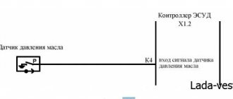
Electrical diagram of the sensor location
The operation of the crankshaft location sensor is based on an effect discovered by the American physicist Edwin Herbert Hall. The device monitors the slightest changes in the strength of the magnetic field induced by a piston magnet installed in the device body. Metal notches (teeth), which are located on the camshaft wheel or on the drive shaft disk, change the strength of the magnetic flux, which is fixed by a semiconductor element.
The camshaft sensor transmits electronic commands to the vehicle's control unit. Based on the data received, the control system accurately calculates the exact angular position of the cylinder piston. Thanks to the accuracy of this process, the gas distribution mechanism of the vehicle operates in optimal mode, effectively supplying the cylinders with an air-fuel mixture and carrying out the timely removal of exhaust gas.
Causes of breakdowns and frequency of regulator replacement:
The camshaft sensor is equipped with a semiconductor chip, the service life of which is reduced when overheated. Due to the fact that the sensor is located on the valve cover, the chip is exposed to increased temperature, which can cause sensor failure.
Over time, the mounting tabs can break, causing the sensor to become dislodged.
Short circuit of the semiconductor chip.
Broken toothed disc, etc.
There are reasons why a sensor can fail at the wrong time.
To ensure that the problem does not take you by surprise, you should practice periodic replacement of the sensor at least once every five years, or after the car has driven 100 thousand. km.
Replacement must be carried out even with smooth and stable engine operation. If the engine stalls for no apparent reason or problems appear with the ignition system, installing a new camshaft sensor is a top priority.
Checking three-wire DPRV
Steps to test a three-wire DPRV:
- remove the air filter cover;
- disconnect the 3-pin connector in the DPRV;
- turn on the ignition;
- using a multimeter and cables from the kit, measure the voltage between terminals 1 and 3 of the sensor connector;
- recommended value: 4.5 to 5.5 V;
- turn off the ignition;
- check the wires between the test box and the 3-pin open circuit connector;
- Recommended wire resistance: max. 1.5 Ohm;
- check the wires for short circuit, to battery (+) and ground (GND);
- If the wires and voltage are ok, replace the camshaft position (CMP) sensor.
IMPORTANT! Before starting any test, the battery voltage must be at least 11.5 volts.
- disconnect the 3-pin camshaft position sensor connector;
- switch DMM to voltage measurement position;
- connect the DMM between the external terminals of the connector;
- Switch the ignition to the “ON” position, but do not start the engine. You should see a minimum of 4.5 volts;
- Now turn the ignition “OFF”;
- connect the VAG 1598/22 test unit to the ECM connector;
- Check the wiring between the test block and the ECM connector using the wiring diagram. Checks must be performed on each of the following points:
- Wire 1 and socket 11.
- Wire 2 and socket 76.
- Wire 3 and socket 67.
- For each of the above tests, the maximum resistance should not exceed 1.5 ohms.
- Check all wires for short circuits.
- when connected and there is voltage between terminals 1 and 3, replace the camshaft position sensor.
- If the wiring is OK but there is no voltage between terminals 1 and 3, replace the ECM.
IMPORTANT! Before starting any test, the battery voltage must be at least 11.5 volts.
- disconnect the 3-pin wire connectors from the camshaft position (CMP) sensors;
- connect the DMM to measure voltage on terminals 1 (+) and 3 (ground) of the CMP connector using the adapters from the test kit;
- turn the ignition to the “ON” position, but DO NOT start the engine;
- Measure the voltage between terminals 1 and 3. It should be a minimum of 9.0 volts;
- turn the ignition “OFF”;
- connect the test block to the ECM connector;
- Check the wiring for open circuit between the ECM and the 3-pin connector according to the wiring diagram;
- For the CMP sensor connector on the right cylinder head, measure the following:
- Connector 1 with ECM connector 11.
- Connection terminal 2 to ECM76 connector.
- Connector 3 with ECM 67 socket.
- maximum resistance should not exceed 1.5 Ohms;
- For the CMP sensor on the left cylinder head, measure the following:
- Connector 1 with ECM connector 11.
- Connector 2 with ECM 44.
- Connector 3 with ECM 14.
- for each of these tests the maximum resistance is 1.5 ohms;
- If the wiring and voltage at terminals 1 and 3 are OK, replace the camshaft position sensor;
- If the wiring is OK but there is still no voltage at terminals 1 and 3, replace the ECM.
Functional test of the CMP sensor:
- To perform a functional test of the camshaft position sensor, disconnect the 4-pin connector from the ignition coil and check the DTC memory;
- check the supply voltage of the camshaft position sensor and make sure that it is in order;
- move away the rubber connector of the CMP sensor (the sensor remains connected);
- connect a voltage tester between terminals 1 (+) and 2 (phase);
- start the engine for a few seconds;
- for every second engine revolution, the voltage tester should flash briefly;
- if the voltage indicator does not blink, turn off the ignition and disconnect the 3-pin connector from the camshaft position sensor;
- connect the test block to the ECM connector;
- Check the signal wire for continuity between terminal 2 and socket B2. The maximum resistance should not be more than 1 ohm;
- If the specified value is not obtained, check for a short or open circuit in the wiring between the CMP sensor connector and the ECM;
- if the wiring is ok, connect the DMM between the B2 test block socket and ground;
- turn the ignition key to the “ON” position. Must be at least 4.0 volts;
- if the specified value is not obtained, replace the ECM;
- If a value is obtained, replace the camshaft position (CMP) sensor.
Replacing the camshaft sensor
Begin the repair by parking the vehicle on a level surface with the engine off and the handbrake applied. Although the appearance and design of the engines of different cars differs, the process is almost identical.
Required tools and supplies:
- new camshaft position sensor;
- set of tools;
- safety glasses and gloves.
Step 1: Remove the camshaft sensor
Locate the sensor by inspecting the front, rear, and top of the engine. The devices are usually located on the side and have a two- or three-wire connector.
To disconnect the connector from the sensor, use a flathead screwdriver. Carefully pull the connector out of the sensor. It may get a little stuck due to the seal inside which is designed to keep moisture out.
Using an 8mm or 10mm wrench (in most cases), remove the camshaft position sensor mounting bolt by turning it counterclockwise. There is usually only one bolt.
Inspect the threads for damage and replace the bolt if necessary. Grasp the sensor and use a twisting motion to pull it out of the housing. It can also get a little stuck due to the o-ring that is designed to control the engine oil.
Once the sensor is removed from its housing, check the electrical terminals for damage or corrosion that will prevent the new sensor from operating.
Step 2: Install a new camshaft sensor
Once the old sensor is removed, wipe down the socket and other components to ensure proper installation. Make sure the sensor has a new O-ring to avoid oil leakage after installation.
To avoid oil leakage and to clean the surface or system components if necessary, use a paper towel. Then apply a small amount of motor oil or WD40 to the O-ring and carefully place the sensor in place. The oil will help prevent damage to the seal during installation.
Insert and tighten the mounting bolt by hand to avoid damaging the threads. Use a small screwdriver or wrench and tighten the sensor mounting bolt. Check the wiring connector to make sure it is free of grease, dirt and corrosion. If necessary, clean it before installing a new sensor. Check the connector wiring because it usually needs replacing.
Install the electrical connector securely. When it is fully installed, you will hear a characteristic click. After installing the new sensor, double check the mounting bolt and connection. Once the repair is complete, connect the programmer to clear the codes and start the engine. The message “PASS” will indicate successful completion of the installation.