Today, every car, regardless of type, is equipped with special protection for all electrical systems. This protection is called a fuse. They are installed so that in the event of a short circuit or malfunction, the system can turn off via a fuse, thereby protecting itself from breakdown. Fuses are used for every electrical circuit, from a small light bulb to an engine's ignition system. More important engine systems are equipped with special relays, they protect various pumps, electric motors and other powerful sources of electricity consumption.
The fuse is a small structure consisting of a plastic casing with a fusible element inside. If a short circuit occurs, the thin contact melts under the influence of current, which interrupts the electric current. The simplest electrical fuse is a thin copper wire inserted into a circuit. If the upper limit of the supplied current increases, the contact begins to melt and interrupts the flow of electricity. Here there is a description of all fuses and relays for VAZ 2113, 2114, 2115 models of injection and carburetor types, old and new models.
Interpretation of fuses and relays of injection models
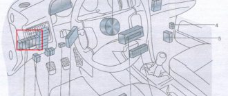
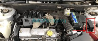
The main electrical fuse module 2114-3722010-60 is located under the front engine compartment. This arrangement allows for quick access to all electrical systems of the car.
Block location
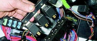
Please note that the location of the electrical fuse module may depend on the type of equipment and year of manufacture of the vehicle. As a rule, this is the upper right part of the engine compartment, under the front windshield. The mounting block is made of plastic in the form of a rectangular box. To protect against accidental opening, the box is equipped with special latches. To open the module, you need to snap off the two protective brackets and lift the top plastic protection. Under the cover are all the main control relays and electrical fuses of the vehicle.
To quickly remove the fuse, special plastic pliers are located on the plastic protection cover. With their help, you can very easily get any element. You need to grab the top edge of the plastic case with pliers and carefully lift the element.
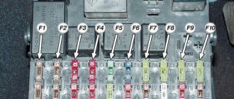
For the convenience of the user, on the top plastic cover there is a complete diagram, made in the form of a schematic image, which shows all the electrical fuses and relays indicating the current strength (A).
Fuse and relay diagram for injection models
Table 1. Explanation of fuses and relays 2114-3722010-60
| № | Current, A | Explanation of fuses |
| F1 | 10 | Rear fog lights, rear fog light indicator lamp |
| F2 | 10 | Turn signals and turn signal breaker relay. Alarm system. Hazard warning lamp |
| F3 | 7,5 | Interior and luggage compartment lighting systems (interior lamp, luggage compartment lamp, ignition key illumination). Brake brake lamp, on-board computer backlight lamp. Engine control lamp |
| F4 | 20 | Rear window heating control. Portable lamp connection socket |
| F5 | 20 | Relay for monitoring and turning on the sound signal. Cooling system engine switch fuse and relay |
| F6 | 30 | Control and relay switching on electric windows |
| F7 | 30 | Electric motor control - heating system, interior heater, windshield washers, headlight cleaners. Interior cigarette lighter, glove box lamp. Turn on the heated rear window. |
| F8 | 7,5 | Turning on the right fog lamp |
| F9 | 7,5 | Turning on the left fog light |
| F10 | 7,5 | Side light for the left side body, indicator light for turning on the side lights (on the display), lamps for illuminating the license plate and engine compartment, illumination lamp for switches, cigarette lighter, heater control levers. Instrument lighting switch. |
| F11 | 7,5 | Right side body marker light |
| F12 | 7,5 | Front right low beam headlight |
| F13 | 7,5 | Front left low beam headlight |
| F14 | 7,5 | Front left high beam headlight. Light indicator lamp. |
| F15 | 7,5 | Front right high beam lamp. |
| F16 | 15 | Body turn signals, relay-breaker for turn signals and hazard warning lights. Control relay and reverse lamps, indicator lamps for the on-board instrument control system, lamps for oil pressure, handbrake activation, brake fluid level, battery charge. On-board computer, engine generator winding. |
| F17-F20 | Spares | |
| № | Relay circuit | |
| K1 | Headlight cleaners | |
| K2 | Turn signals and hazard warning lights | |
| K3 | Windshield wiper | |
| K4 | Monitoring the serviceability of brake light lamps and side lamps | |
| K5 | Window lifters | |
| K6 | Sound signal | |
| K7 | Heated rear window | |
| K8 | High beam headlights | |
| K9 | Low beam headlights | |
Location of fuses in Grant
- since 2011
- from 2022
“INSTALLATION No. 8-15 On LADA GRANT vehicles manufactured between 07/04/2014 and 01/19/2015, a problem may appear in the form of “the engine does not start, fuse F1 in the mounting block has blown” ...” If this is your case - The factory recommends updating the engine control unit program from an authorized dealer. It sounds strange, but it helps.
All fuses and relays of Lada Granta, Lada Granta Liftback, Granta Lux, Granta standard, Granta Norma, VAZ 2190, VAZ 2191 - 2011, 2012, 2013, 2014, 2015, 2016, 2022, 2022, 2022, 2022 model years.
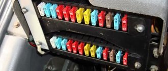
Most fuses are located in the vehicle interior under the instrument panel on the driver's side, behind a protective cover on which the relays and fuses of the main unit are marked on the reverse side.
To open the fuse box cover, pull the lower left corner of the cover
Decoding fuses and relays of block 2114-3722010-18
VAZ-2114, 2115, 2113 cars of the first models with a carburetor have certain differences in the fuse module.
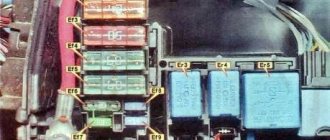
Old style block fuse and relay diagram
Table 2. Decoding of fuses and relays of block 2114-3722010-18
| № | Current, A | Explanation of fuses |
| F9 | 7,5 | Right rear fog lamp |
| F8 | 7,5 | Left rear fog lamp |
| F1 | 10 | Front headlight cleaners at the moment of switching on, wiper contacts, headlight washer switch valve, headlight wiper switch relay contacts |
| F7 | 30 | Front headlight wipers during operation, winding of the relay for turning on the wipers, fuse for the interior heater, windshield washer, gearbox and timing controller for the rear window wiper, valves for turning on the front and rear washer, relay (winding) for turning on the engine cooling system, relay for turning on the rear window heating, glove box lighting, rear window heating control lamp |
| F16 | 15 | Turn signal indicators and activation of hazard warning lights in turn mode, indicator control lamp, reversing lights, gearbox and relay for activation of windshield washers, generator winding (at startup), control lamps for brake fluid, oil pressure, carburetor flap, hand brake. "STOP" display lamp, voltmeter and coolant temperature indicator |
| F3 | 10 | Interior lighting and rear brake light |
| F6 | 30 | Power windows, power windows on/off relay |
| F10 | 7,5 | License plate lights, engine compartment lamp, warning light on the dashboard (exterior lighting), instrument panel lights, cigarette lighter light, heating lever lights |
| F5 | 20 | Relay for turning on the cooling system fan (electric motor), sound signal. |
| F10 | 7,5 | Left front marker light Left rear marker light |
| F11 | 7,5 | Right front headlight, right rear |
| F2 | 10 | Hazard warning lamp, turn signals and hazard warning relay. |
| F4 | 20 | Rear heated glass, heating on, portable socket, cigarette lighter in the cabin |
| F15 | 7,5 | Front right high beam |
| F14 | 7,5 | Front left high beam Light switch |
| F13 | 7,5 | Left low beam |
| F12 | 7,5 | Right low beam |
| № | Relay circuit | |
| K1 | Headlight washers | |
| K2 | Hazard and turn signals | |
| K3 | Windshield wipers | |
| K4 | Monitoring the health of lamps | |
| K5 | Windows | |
| K6 | Sound signal | |
| K7 | Heated rear window | |
| K8 | High beam headlights | |
| K9 | Low beam headlights | |
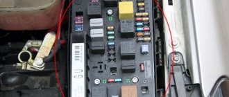
Location of the fuse box under the hood of the Lada Granta
| № | Current strength, A | What protects |
| F1 | 30 | Low beam headlights or main relay, circuits protected by fuses F1 and F21 of the mounting block in the passenger compartment |
| F2 | 60 | Generator |
| F3 | 60 | Generator |
| F4 | 30 | Heater fan (heater fuse) |
| F5 | 50 | Electric power steering |
Starter, ignition, rear fog lamp relay
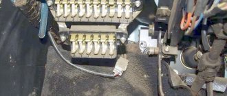
In order to carry out quick checks and repairs, the ignition system relay is installed under the front dashboard of the car, behind the hood release handle. It is located just below the central dashboard. The module is closed with a plastic plug, which must be opened slightly to test for functionality.
Starter, ignition, rear fog lamp relay
Next to the indicated relay, there is a similar one for the rear fog lights and the starter.
The main task of the relay when igniting is to reduce the applied load to the contacts. When the engine starts, the relay turns off some electrical circuits in the vehicle system. The system is used not only in injection, but also in carburetor engines.
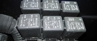
In the event of a malfunction or malfunction in the ignition system, it is necessary to monitor the operation of the relay. For this purpose, open the box and carefully remove the desired element. It is attached using contacts to special grooves. The first thing to do is look at the oxidation of the contacts, if necessary, clean them with a soft cloth or treat them with a special liquid.
To check functionality, you need to use a regular multimeter. We connect to incoming connections and check the numbers. If there is no short circuit when current is applied, it means the element is not working. Replacement is carried out in a similar manner. It is necessary to use a standard element with the number of amperes indicated on the housing.
Unexpected reasons for non-working PTFs on the VAZ-2110
The most common cause is a blown fuse.
But we will return to it later. There is still a lot that is still unknown in the design of foglights, relays, switches and lamps. For example, a possible reason for the failure of fog lights could be a completely unexpected breakdown.
First of all, we check the bulbs themselves; you can get to the left one through the hood.
On some versions of the VAZ-2110, a PTF from the Avtosvet plant (Kirzhach) was installed with a socket for the H1 lamp. Stock lamps are not the best quality and they do not like sudden changes in temperature.
Front fog lamp relay
Front fog lights are not standard equipment on the model and are equipped depending on the configuration. The relay itself (if there are fog lights) is located in the engine compartment on the left mudguard.
Front fog lamp relay
Important! To access the relay, you must remove the battery! Without performing this manipulation, it will be difficult to remove and check its functionality.
Replacing a faulty element is very simple. You need to take a Phillips screwdriver (with a short handle), unscrew the bolt securing the relay to the car body, and check the element for malfunction. If it fails, we buy a new one and put everything in the reverse order.
Where are the fuses on the Priora?
- The main mounting block of the Priora is closed with a lid and located at the driver’s left foot. To open it, you need to turn three latches 90° and unclip the lid.
- The fuse box is under the hood, which is located near the expansion tank.
- Another mounting block, which is located near the left foot of the front passenger. To gain access to the fuses and relays, unscrew several screws with a Phillips screwdriver.
Below is a description of each fuse and relay block in order.
The VAZ 2114 has two blocks
The electrical circuit of the VAZ 2114 fuses is divided into two mounting blocks:
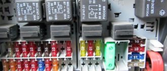
The main set of instruments is mounted under the hood on the left side (when viewed from the driver's position). The plastic cover is held on by latches, with the help of which it can be easily snapped off and can then be removed. The inside of this cover is equipped with a layout diagram that shows the rated current for each element. A detailed electrical diagram of the mounting block with the order of connecting contacts to the plugs is shown in the Lada 2114 instruction manual.
It is not allowed to insert a fuse whose amperage exceeds the permissible values in the circuit. This puts electrical equipment at risk. There are tweezers in the upper right corner of the mounting block. The design of this unit provides seventeen working fuses (which are schematically named F1-F16) and four backup protective elements (F17-F20): gray (2 A), pink (4 A), yellow (20 A); green (30 A).
The second mounting block of the VAZ 2114 is located in the cabin under the glove compartment, to the right of the central instrument console. You can get to it by moving the passenger seat all the way back. This mounting block includes a protective element for the fuel pump (with a rated current of 15 A). The remaining ES are designed to protect the fan relay, speed sensor (built into the gearbox), and mass air flow sensor.
The rated amperage of the element is 7.5 A. An element with the same rated current is provided for the ignition unit and ECU.
PTF connection diagram
But sometimes it happens that the PTFs refuse to turn on, and either one or both headlights may not work. There can be many reasons why the fog lights on a VAZ 2114 do not light up, but the main one is the appearance of oxides or corrosion in important places in the electrical circuit leading to the headlights.
Before considering all possible causes in more detail, you should familiarize yourself with the schematic diagram of connecting fog lights to the vehicle’s on-board electrical system.
It looks like this:
It contains the following symbols:
- pink rectangles 10A - 10-amp fuses;
- F1 and F2 - fog lights;
- grounding icon - connection to ground;
- +12V — output to the “+” terminal of the battery.
Replacing the VAZ 2114 fuse
Often, car electrical breakdowns are caused by a blown fuse. Before checking components, contacts, and wiring for damage, the fuses are always checked first. If the integrity of the element is compromised, it simply needs to be replaced.
First, we determine which device is faulty and where its fuse is located. When further troubleshooting, you must disconnect the “—” terminal of the battery. Open the hood, remove the cover of the VAZ 2114 mounting block, take tweezers and pull out the fuse that is supposedly blown. Do not use a metal screwdriver or other tools to work on fuses.
There are external signs by which you can visually determine whether it has burned out or not. But the most reliable check is with the help of a tester. We set the multimeter to the continuity mode and apply the probes to the contacts of the electrical circuit. If the product is working properly, the tester will show a resistance of 0 and emit a sound signal.
If the fuse element is destroyed, the fuse must be replaced. The cost of the product varies between 150–350 rubles, depending on the type.
- Electrical equipment
- Engine
- Brake system
- Other
- Steering
- Transmission
- Suspension
- Tuning
- VAZ 2110
- Other
- Engine
- Steering
- Electrical equipment
- Transmission
- Brake system
- Suspension
- Tuning
- VAZ 2114
- Electrical equipment
- Engine
- Brake system
- Other
- Steering
- Transmission
- Suspension
- Tuning
- Lada Priora
- Steering
- Engine
- Suspension
- Electrical equipment
- Tuning
- Brake system
- Transmission
- Video publications
- VAZ tuning photo stream
- Operation and repair manuals