The road along which the driver chooses a route is not always level and smooth. Very often, it may contain such phenomena as uneven surfaces - cracks in the asphalt and even bumps and potholes. Don't forget about speed bumps. This negative would have a negative impact on driving comfort if there were no shock-absorbing system - the car's suspension.
Purpose and device
While driving, road unevenness in the form of vibrations is transmitted to the body. The vehicle's suspension is designed to dampen or soften such vibrations. Its application functions include providing communication and connection between the body and the wheels. It is the suspension parts that give the wheels the ability to move independently of the body, allowing the vehicle to change direction. Along with the wheels, it is an essential element of the car's chassis.
A car suspension is a technically complex unit that has the following structure:
- elastic elements - metal (springs, springs, torsion bars) and non-metallic (pneumatic, hydropneumatic, rubber) parts, which, due to their elastic characteristics, take the load from road unevenness and distribute it to the car body;
- damping devices (shock absorbers) - units that have a hydraulic, pneumatic or hydropneumatic structure and are designed to level body vibrations received from an elastic element;
- guide elements - various parts in the form of levers (transverse, longitudinal) that provide connection between the suspension and the body and determine the movement of the wheels and body relative to each other;
- anti-roll bar - an elastic metal rod that connects the suspension to the body and prevents the car from increasing roll while driving;
- wheel supports - special steering knuckles (on the front axle) that absorb the loads coming from the wheels and distribute them over the entire suspension;
- fastening elements for parts, components and assemblies of the suspension are means of connecting suspension elements with the body and among themselves: rigid bolted connections; composite silent blocks; ball joints (or ball joints).
Designs of elastic elements
Multi-leaf springs are the most functional and simplest elastic element in design. At the same time, springs perform the functions of an elastic element, a guide and a damping device.
The disadvantage of leaf springs is their high metal consumption. The elastic deformation energy (potential deformation energy) related to the mass of a leaf spring is 2...3 times less than that of springs and torsion bars. Currently, semi-elliptical springs, symmetrical and asymmetrical, are mainly used.
Asymmetrical springs with a shorter (more rigid) length of the front part than the rear part make it possible to reduce the “dive” of the car when braking, thus partially performing the functions of a longitudinal stability stabilizer. The spring (Fig. 1, a) consists of sheets of the same width but different lengths assembled together.
The curvature of the sheets increases as their length decreases. The thickness and cross-sectional profile of the sheets (rectangular, parabolic, trapezoidal) can be different. Their choice is determined by the nature of the stress distribution along the length of the sheets and the level of permissible stresses.
Each of the spring leaves has holes for a central bolt, which is used to tighten the sheets before installation. The sheet or several sheets by which the spring is attached to the supporting system are called main sheets.
The ends of the main sheets are additionally processed - an eye is formed (Fig. 1, 6) or holes are punched to install parts for fastening the spring to the frame (body) of the car in one of the following ways: brackets for fastening using fingers or cups of rubber supports. To bring the spring structure closer to a beam of “equal” resistance, in which the bending stresses in each section of the sheets are equal in length, the ends of the remaining sheets can be pulled back (Fig. 1, c) or cut off along a trapezoid.
Rice. 1. Multi-leaf spring
Few-leaf and single-leaf springs (Fig. 2) are closer to the shape of a beam of equal resistance than multi-leaf springs. The cross-sectional height h of the sheet l of the spring at the point of attachment to the bridge beam 3 using stepladders 2 is determined from the strength condition at a given load. With a constant width b of the sheet, the height h of its sections along the length of the sheet varies along a parabola. The thickness of the ends made of alloy steels: chromium-manganese - 50KhG, 50KhGA, silicon-manganese 55GS and silicon 60S2.
Rice. 2. Leaf spring
The durability of leaf springs to this day remains less than the durability of other elastic elements, even when using special methods of metal hardening and sheet surface treatment. In addition, the difficulty of creating an independent spring suspension, the large mass of unsprung parts and friction between the spring leaves are the reasons for the decrease in ride smoothness.
Spiral springs (Fig. 3) are distinguished by their simplicity of design and at the same time high specific energy intensity.
Rice. 3. Coil spring
Given the short and simple manufacturing cycle, springs have become the most common elastic elements in car suspensions. When creating a spring with a variable pitch, a progressive change in spring stiffness is ensured. The advantage of such an elastic element is its compactness, low weight and ease of arrangement of suspension parts. A shock absorber or a hydraulic suspension strut can be placed inside the spring. It is important to ensure the immobility of the springs relative to the supports, for which the design of the ends of the springs or the support coils as a whole must meet certain requirements.
The lowest relative cost are springs whose ends are cut at right angles and tightened. A more expensive version of the spring is to press and grind the support coils to a plane. The main advantage of flat support coils is their simplicity, and therefore ease of production of spring support parts. Springs are easy to manufacture and inexpensive, the ends of which are twisted inside the spring to form a supporting surface. In addition to reducing the overall length of the spring, they provide easy installation on supporting surfaces. The disadvantage of such springs is that they cannot be installed inside shock absorbers.
Torsion bars, along with springs and springs, are widely used as elastic elements of suspensions.
A torsion bar is a shaft (rod) that produces torsion. Torsion bar suspensions, with equal energy intensity, have a significantly lower mass of the elastic element compared to a spring and have better suspension layout capabilities even compared to spring elastic elements. The last advantage is especially obvious when designing the suspension of the driving wheels of a car. Car suspensions use torsion shafts with cross sections shown in Fig. 4.
Basically, the cross-section of the torsion bar is a circle or ring, including a split one (Fig. 4, a, 6, c). In some designs, the torsion bar is made up of several rods (Fig. 4, d) or strips of the same or different widths (Fig. 4, e, f). Plate torsion bars are a set of strips of equal length with a square-shaped cross-section, subject to twisting during operation. It is economically feasible to produce plate torsion bars from sheets with identical section sizes.
Strips of the required thickness for stacked plate torsion bars are produced by rolling, which ensures compliance with stringent requirements for the accuracy of dimensions of the width and height of the profile. The use of cylindrical torsion bars with a circle or ring in cross-section most closely meets the requirements for the effective use of elastic element material in the case where the length of the rod is not limited by design and parameters.
Rice. 4. Sections of torsion bars
Cylindrical torsion bars work well not only under single impacts with a maximum stress level, but under constant high-level stresses. This is ensured by hardening and grinding the surface along the working length of the torsion bar. The design of the end sections is of great importance for cylindrical torsion bars. To transmit torque, it is technologically and structurally advisable to produce splined ends with a small profile. Such surfaces can be obtained by rolling or cutting, which ensures the alignment of the ends of the torsion bar.
A significant advantage of torsion bar suspensions is the ability to relatively easily adjust the height of the car or correct the roll in case of uneven settlement of the elastic elements. Therefore, in many cases, manufacturers use relatively complex designs for fastening the ends of the torsion bar with a large number of parts, but providing stepless adjustment of the suspension. The design of the end sections in these cases can be different, for example, with a square or hexagonal section.
Rubber elastic elements in car suspensions are used as additional elastic elements that work in compression, torsion or shear. Rubber elastic elements are much cheaper and more technologically advanced to manufacture than any metal elastic elements. To fasten the rubber compression spring 2 (Fig. 5), use a metal bushing 1, installed in the mold before vulcanization.
Rice. 5. Rubber elastic element
Many car manufacturers have long and successfully used rubber elastic elements in the designs of vehicle suspensions for a wide variety of purposes in a wide range of variations and technically permissible weights.
The advantage of rubber elastic elements is their progressive characteristic, which ensures a significant increase in the rigidity of the elastic element as it deforms. The main restrictions on the use of such elements are associated with disadvantages determined by the quality of the source material and manufacturing technology.
Pneumatic elastic rubber-cord elements (Fig. 6) are used on vehicles (buses, trucks, semi-trailers), the weight of the sprung masses of which can vary significantly.
Rice. 6. Pneumatic elastic element
Pneumatic elastic elements have low weight, high durability and progressive non-linear elastic characteristics. They are made of two-layer rubber-cord shells. To reduce rigidity and reduce its change during suspension deformation, the pneumatic element can be supplemented with metal containers, one or two, positions 1 and 2.
Hydropneumatic elastic elements (Fig. 7) differ in that the elastic element is a chamber with compressed inert gas under high pressure, and the working fluid transmits the vertical load.
Rice. 7. Hydropneumatic element
The normal reaction force Q from the wheel is transmitted to the gas in chamber 1 using the piston 4 of the hydraulic telescopic strut, the working fluid filling the cylinder 3, and the piston 2 of the elastic element. The gas pressure in the elastic element can reach 20 MPa, which ensures its compact dimensions. Damping of vibrations of the sprung mass is ensured by throttling the fluid through valves 5 and 6.
Principle of operation
The operation of a car's suspension is based on the conversion of the impact energy arising from a wheel hitting an uneven road surface into the movement of elastic elements (for example, springs). In turn, the rigidity of the movement of elastic elements is controlled, accompanied and softened by the action of damping devices (for example, shock absorbers). As a result, thanks to the suspension, the impact force that is transmitted to the car body is reduced. This ensures smooth running. The best way to see the system in action is to use a video that clearly demonstrates all the elements of a car's suspension and how they interact. Cars have suspensions of varying stiffness. The stiffer the suspension, the more informative and efficient the car control. However, this seriously compromises comfort. And, on the contrary, the soft suspension is designed in such a way that it provides ease of use and sacrifices controllability (which cannot be allowed). That is why car manufacturers are striving to find their best option - a combination of safety and comfort.
Pendant type "De Dion"
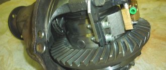
This type, as well as the McPherson suspension, was named after the inventor. It was the Frenchman Albert De Dion. The purpose of this type of suspension is to minimize the load on the rear axle of the car by separating the final drive housing. If previously it was attached to the bridge beam itself, in this case the crankcase is held directly on the body.
This allows you to transmit torque through axle shafts mounted on CV joints, and make the suspension both independent and dependent.
But the De Dion type could not get rid of the main disadvantages of all dependent suspension options. For example, it is almost impossible to brake without “pecking”, and with a sharp start the car simply “squats” on the rear wheels.
Despite attempts to eliminate these shortcomings by installing additional elements (guides), the unbalanced behavior of the car remains the main problem.
Variety of suspension options
The vehicle suspension device is an independent design solution of the manufacturer. There are several typologies of car suspension: they are distinguished by the criterion underlying the gradation.
Depending on the design of the guide elements, the most common types of suspension are distinguished: independent, dependent and semi-independent.
The dependent version cannot exist without one part - a rigid beam that is part of the car axle. In this case, the wheels move parallel in the transverse plane. The simplicity and efficiency of the design ensures its high reliability, preventing wheel alignment. That is why dependent suspension is actively used in trucks and on the rear axle of cars.
The independent suspension system of a car assumes that the wheels exist autonomously from each other. This improves the damping characteristics of the suspension and ensures a smoother ride. This option is actively used for organizing both front and rear suspension on passenger cars.
The semi-independent version consists of a rigid beam secured to the body using torsion bars. This scheme ensures relative independence of the suspension from the body. Its typical representative is the front-wheel drive VAZ models.
The second typology of suspensions is based on the design of the damping device. Experts distinguish hydraulic (oil), pneumatic (gas), hydropneumatic (gas-oil) devices.
The so-called active suspension stands apart. Its design includes variable capabilities - changing suspension parameters using a specialized electronic control system depending on the vehicle's driving conditions.
The most common parameters to change are:
- degree of damping of the damping device (shock absorber);
- degree of rigidity of the elastic element (for example, a spring);
- degree of rigidity of the anti-roll bar;
- length of guide elements (levers).
Active suspension is an electronic-mechanical system that significantly increases the cost of the car.
Hydraulic telescopic shock absorbers
Hydraulic shock absorbers provide damping of vibrations of the sprung part of the car and are the main structural elements that influence the smoothness of movement and the conditions of contact of the tires with the supporting surface. By design, shock absorbers are divided into two types: twin-tube and single-tube.
The design of monotube shock absorbers is recognized as more technologically advanced, but their effectiveness can be reduced due to the elastic components of the forces acting on the sprung masses. Twin-tube shock absorbers do not have this drawback. As a rule, modern vehicles use “double-acting” shock absorbers, which create resistance and dampen vibrations both during the “compression” and “recoil” strokes.
A double-acting hydraulic telescopic double-pipe shock absorber (Fig. 21) consists of the following main parts: cylinder 1 with a compression stroke valve body 2 fixed in its lower part; rod 3 with piston 4 and guide sleeve 5; shock absorber housings 6.
Rice. 21. Hydraulic telescopic twin-pipe shock absorber
Eye 7 of body 6 is connected to the suspension guide device, and eye 8 of the rod is connected to the sprung part of the vehicle. The piston 4 has holes 9, evenly spaced at an equal distance from the axis of the rod, and holes 10, also located on the circle, but with a larger radius. Holes 10 are covered by a check valve plate 11, and holes 9 are covered by a rebound valve plate 12, pressed against the piston by a spring 13. Housing 2 contains: a compression stroke valve 14, which closes the holes 15, and a check valve 16, which closes the holes 17 located around the circumference. Valve 14 is loaded by the elastic force of spring 18, pressed by nut 19. The cylinder and part of the reservoir 20 (cavity B) are filled with special oil; the upper part of cavity B contains air, which allows one to compensate for changes in the volume of liquid when the rod moves.
The piston relative to the cylinder is sealed using rings 21, the guide rod 5 and the seal ring 25 are sealed relative to the body using ring 22. The most complex is the rod seal a, consisting of anthers 26, an oil seal 27, constantly pressed by a spring 24 and a ring 23. The liquid carried out by the rod from the cylinder is drained into the cavity of reservoir B through holes A.
The shock absorber operates in two modes: throttle and valve. When the rod moves “smoothly” (throttle mode) during compression, liquid flows freely from cavity B to cavity D through holes 10. The volume of cavity D is less than the volume of cavity B by a volume equal to the volume of the rod, so excess liquid flows through holes 15, which are not closed check valve 16, compression valve clearances 14 into the tank cavity. With a “sharp” stroke of the piston, the unloading valve 14 opens, the pressure in cavity B and the resistance force are limited and no longer increase. During the recoil stroke, holes 10 in piston 4 are closed by check valve 11. Liquid from cavity g to cavity
B passes through holes 9, in throttle mode through the gaps of valve 12, and during a sharp stroke, through the open valve 12. The lack of liquid in cavity B is compensated by the flow of liquid from the reservoir cavity through holes 17, open valve 16 into cavity d.
A single-pipe telescopic hydraulic shock absorber with a gas chamber (Fig. 22) has a simpler design than a double-pipe one.
Rice. 22. Monotube shock absorber
It consists of a working cylinder 3, inside of which there is a rod 1 with a piston 2. The seal of the rod relative to the cylinder is ensured by seals 6. The shock absorber chamber 5 is filled with compressed inert gas. The gas chamber is isolated from the liquid by a separating piston 4. In the piston 4 (Fig. 22, a, b) there are two rows of through obliquely located holes 9 and 10. The internal holes are closed at the top with a compression valve 7, and at the bottom with a rebound valve 8. The valves consist of thin steel disks of the same thickness, assembled in a package. At the exit points of the inner row of holes, the piston has calibrated grooves through which fluid passes when the shock absorber operates in throttle mode.
In valve mode, the fluid pressure increases, and the valve discs bend, and the valve flow areas increase. In Fig. 22, b shows the operation of the valves during the compression stroke, in Fig. 22, during the lights out.
Main types of independent suspension
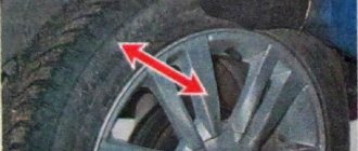
In modern passenger cars, an independent suspension option is often used as a shock-absorbing system. This is due to the good controllability of the car (due to its low weight) and the absence of the need for total control over the trajectory of its movement (as, for example, in the case of a truck). Experts distinguish the following main types of independent suspension. (By the way, the photo will allow you to more clearly analyze their differences).
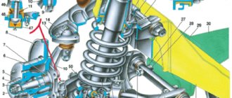
Double wishbone suspension
The structure of this type of suspension includes two levers attached to the body with silent blocks, and a coaxially located shock absorber and coil spring.
MacPherson strut suspension
This is a derivative (from the previous type) and a simplified version of the suspension, in which the upper arm was replaced by a shock absorber strut. Currently, MacPherson strut is the most common front suspension design for passenger cars.
Multi-link suspension
Another derivative, improved version of the suspension, in which two wishbones were “separated” as if artificially. In addition, the modern version of the suspension very often consists of trailing arms. By the way, multi-link suspension is the most commonly used rear suspension design for passenger cars today.
Torsion bar suspension
The design of this type of suspension is based on a special elastic part (torsion bar), which connects the lever and the body and works to twist. This type of design is actively used in organizing the front suspension of some SUVs.
What problems are the car suspension elements designed to solve?
The history of suspension dates back to the times of horse-drawn carriages, when the system of attaching wheels to the carriage cabin was very basic and did not have any shock-absorbing mechanisms. When driving on uneven roads, the passengers of such a carriage were shaken violently. In the struggle for comfort, engineers began to come up with designs that could soften cabin vibrations.
The first devices to perform shock-absorbing functions were elliptical springs. Over time, the spring mechanism began to be used on cars. By that time, the springs were already made in a semi-elliptical shape, and they were installed transversely, which turned out to be not the best solution for the car, because there were problems with its handling, even at low speeds. To solve this problem, manufacturers began to install springs longitudinally on each wheel separately.
Today, automotive technology has come a long way. Designers have developed various types of suspensions, and each type has certain features that affect not only the handling of the car, but the comfort of people while traveling. Despite the variety of designs, any suspension option must perform basic functions:
- Damping vibrations, as well as strong shocks that occur when moving on an uneven surface.
- Ensuring maximum wheel adhesion to the road surface, as well as eliminating car body roll when cornering.
- Increasing vehicle controllability by keeping the wheel in a given position.
In order for the car to be as stable as possible on the road during dynamic driving, a rigid type of suspension is used. This type of suspension provides the car with good handling at high speeds, eliminates body roll when cornering and provides an immediate response to driver inputs.
Despite all the advantages of a rigid suspension, passenger comfort during the trip cannot be called satisfactory, since due to rigidity, the ability to smooth out body vibrations is reduced. For normal driving, many passenger cars have soft suspension. The vehicle's handling is reduced, but the ride also becomes much more comfortable, which is a more important parameter for the average motorist.
Some automakers produce cars with adjustable suspension stiffness. This function is provided by the ability to adjust the spring tension of the shock absorber struts.
In addition to varying stiffness, the suspension can have different degrees of travel. The distance between the position point of the wheel with the springs maximally compressed and the position point in the maximum suspended state is called the suspension travel. The increased travel helps the car overcome obstacles on the roads without the risk of the wheel hanging out and the strut hitting the limiter.
We recommend
“Diagnostics and repair of the rear suspension of a car” Read more
Front suspension adjustment
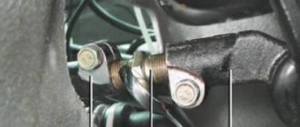
An important component of a comfortable ride is the correct adjustment of the front suspension. These are the so-called steering wheel alignment angles. In common parlance, this phenomenon is called “wheel alignment”.
The fact is that the front (steered) wheels are installed not strictly parallel to the longitudinal axis of the body and not strictly perpendicular to the road surface, but with certain angles that provide tilts in the horizontal and vertical planes.
Correctly set wheel alignment:
- firstly, it creates the least resistance to vehicle movement, and, therefore, simplifies the process of driving;
- secondly, it significantly reduces tire tread wear; thirdly, it significantly reduces fuel consumption.
Installing corners is a technically complex procedure that requires professional equipment and work skills. Therefore, it should be performed in a specialized institution - a car service center or service station. It’s hardly worth trying to do this yourself using a video or photo from the Internet if you have no experience in such matters.
Suspension faults and maintenance
Let’s make a reservation right away: according to Russian legal norms, not a single suspension malfunction is included in the “List of…” malfunctions with which driving is prohibited. And this is a controversial point.
Let's imagine that the suspension shock absorber (front or rear) does not work. This phenomenon means that driving over every bump will be associated with the prospect of body rocking and loss of vehicle controllability. What can we say about the completely loose and unusable ball joint of the front suspension? The result of a malfunction of a part - “the ball has flown out” - threatens a serious accident. A broken elastic suspension element (most often a spring) leads to body roll and sometimes an absolute inability to continue moving.
The malfunctions described above are the final, most odious malfunctions of the car suspension. But, despite their extremely negative impact on traffic safety, operating a vehicle with such problems is not prohibited.
Monitoring the condition of the vehicle while driving plays an important role in suspension maintenance. Creaks, noises and knocks in the suspension should alert and convince the driver of the need for service. And long-term operation of the car will force it to use a radical method - “change the suspension all around,” that is, replace almost all the parts of both the front and rear suspension.
What else is worth reading
Parking brake
Adjusting the parking brake
Car torsion bar suspension
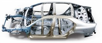
Types of car bodies
Anti-roll bar
Semi-independent rear suspension
This scheme has become widespread and is used in the design of most modern all-wheel drive vehicles. It consists of two longitudinal arms, which are attached to the cross member in the center. This type of suspension has many advantages:
- Small sizes;
- Light weight;
- Ease of maintenance and repair;
- The best kinematics of the wheels;
- Significant reduction in unsprung masses.
There is only one disadvantage of this design - it cannot be used on rear-wheel drive vehicles.