Automatic DRL controller
Author: CAMOKAT-BETEPAHA Published 07/30/2013 Created with the help of KotoEd.
The controller controls the inclusion of DRLs when necessary. This is the main task, although it can be applied in other areas. The signal for turning it on and off is the voltage of the on-board network and also the signal from the vehicle’s dimensions.
The controller has the ability to adjust the threshold for turning on and off the DRLs, and it is also possible to configure not the complete extinction of the DRLs when the lights are turned on, but the choice of any brightness level of the DRLs from zero to maximum.
The controller has smooth ignition and smooth decay.
The setup algorithm is simple:
There are two control buttons: “Minimum” and “Maximum”. With the engine off and the generator not running, press the “Minimum” button. The controller remembers the minimum voltage value. Next, the engine needs to be started, the generator starts working, the voltage in the on-board network increases - press the “Maximum” button. All setup is complete. Now the controller monitors the voltage of the on-board network, and if the voltage exceeds two-thirds of the minimum-maximum difference, then the DRLs will work. In order for the DRLs to go off, the voltage must drop below one-third.
If the headlights are turned on and the DRL operation is enabled, the brightness will change to the level to which the brightness level control potentiometer is turned. You can make sure that when you turn on the DRLs they go out completely, or you can adjust a third of the brightness, for example, or any other brightness level.
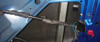
To connect the controller, you need to connect four wires: ground, + ignition, dimensions and output to DRL.
There are three operating modes: 1. — Main mode, when switching on occurs at 2/3 of the voltage, and switching off at 1/3 of the on-board network voltage. As described above in the link. The operating condition for this mode is that the minimum threshold must be higher than the maximum. That is, they turned on the ignition, pressed the MIN button, then started the car - pressed the MAX button.
2 — Selected threshold mode without a hysteresis loop, as in the first version of operation. The condition for selecting this mode: you need to press two buttons at the same time, after which the voltage on board the network at which the setting buttons were pressed will be considered the threshold. Exceeding this threshold above immediately turns on the light, below - turns it off.
3. — Fixed threshold mode at 13.8 Volts. The condition for selecting this mode: you need to do the opposite, press the MIN button when the engine is running, and the MAX button when the engine is off. In other words, the maximum threshold value must be less than the minimum.
The result is a fairly universal craft, which can, for example, be used to control a generator or control the excess of any voltage somewhere or, conversely, its decrease.
Attached is the firmware, diagrams and everything you need for assembly, a list of components, including sources:
Hello, dear friends! I think many people are interested in an effective connection diagram for DRLs, that is, daytime running lights.
For several years now, there have been rules in the country according to which, when driving a car during the day, you should indicate your presence with the help of appropriate headlights. Fog lights, low beam headlights and the DRLs themselves are used as such lamps.
The use of fog lights and headlights has objective disadvantages. Therefore, it is best to connect the DRLs from the generator or battery yourself.
There are various ways and schemes for implementing the idea. Some do this without a relay, others combine DRLs with turn signals, others even control the daytime lights with a separate button, etc. To do everything right, you need to know some important points. And then automatic activation will be carried out without violating traffic rules.
Nuances of using lights
There is a special GOST that defines and regulates installations, technical parameters and the connection itself of daytime running gears.
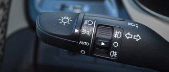
The regulations state that the circuit should be used in such a way that the drive wheels turn on automatically when the key is turned in the ignition switch. That is, when starting the power plant. But DRLs are also required to turn off automatically as soon as the main beam headlights come on. Here, as you understand, we are talking about the headlight unit (low or high beam). There is also a rule indicating that the head light should turn on only when the headlights turn on. The exception is short-term signals to warn other drivers.
Based on the above, we can safely say that you should not output the DRL through the button. The same as through the handbrake. But you can install it in turn signals, but you will need to connect 2 additional wires from each turn signal.
All this is extremely important to take into account when connecting the movers. After all, you should be concerned not only with the fact that the light bulbs do not burn out. Although this is an extremely significant point.
Without a well-thought-out and competent scheme, you will definitely not be able to install DRLs yourself. After all, everything should work with a shutdown when the high or low beam is turned on.
There are a number of schemes according to which, in theory, you can install DRLs on your car if they are not included in the standard configuration of your vehicle. The only question is which scheme is better to use.
An important role is played by the voltage stabilizer, which is a subject of much debate when using diode running lights. The DRLs themselves are equipped with resistors that act as a current limiter. But during voltage surges, they are not able to maintain the voltage at a single level. Therefore, it is correct to assume that the use of a stabilizer in such a scheme will be mandatory and necessary. Otherwise, the service life of the DRL will be significantly reduced due to regular voltage drops. Although some still believe that the connection can be made without a stabilizer.
Connection diagrams for DRLs with turn signal function
There is no single scheme suitable for all car models, since their designs are different. And the blocks themselves are also different. Therefore, it is best to look at forums where owners of a particular model communicate; there, most likely, you will find many connection options, and tested in practice.
For example, you can use the following schemes:
- connection to the cigarette lighter, if power is supplied to it when the engine is turned on. This will ensure that the running lights turn on at the same time. This is suitable, for example, for Dusters;
- connection to the speed sensor. Switching on will occur when you start driving, and switching off when stopping;
- connection to the oil sensor. Switching on will occur when the engine starts;
- connection to the generator.
All these are common schemes that are assembled with your own hands. There are many others like this. They are suitable for those who like to make and solder various devices themselves.
But how to connect DRLs with a turn signal function from a ready-made kit? This is the simplest option, anyone who knows how to hold a screwdriver can handle it, but it will take a master a few minutes. The control unit is connected simply:
- the black wire is connected to the negative of the battery, and the red wire to the positive;
- The orange wire connects to the headlights or low beam. It is needed to turn off the lights when the low beam or side lights are turned on. This wire is not always available.
If the DRL bulbs and the turn signal are structurally located in the same lamp, they still have different contacts that are connected according to the attached diagram.
It couldn't be simpler
This is the simplest scheme, which involves connecting to a battery or generator as a power source.
The scheme provides that the DRLs will be activated simultaneously with the engine starting. The point is to connect the plus to the positive terminal from the ignition switch of your Renault Logan or the same Lada Largus, and fix the minus on the car body in any convenient place. Everything looks simple and extremely logical. But you should not rush to conclusions, nor should you make such a connection. After all, it has an obvious drawback.
If the system is assembled according to this scheme, the diodes from the DRLs will start working constantly while the key is in the ignition switch. There is no question of any coordination with other headlights here. Therefore, such a connection contradicts GOST and traffic regulations.
Low beam or dimensions
You can also connect to the side lights or low beam headlights. In theory, everything here also looks quite simple, interesting and promising.
The first of the schemes under consideration provides that you will use an electrical circuit that powers the size lamps. Here the plus from the DRL is connected directly to the battery as a power source. But the minus goes to the plus of the dimensions. At such a moment the latter will be electrically neutral. Thus, the current flows from the plus of the battery through the diodes to the dimensions, and then through the lamp to the housing, where the latter acts as a minus of the created electrical circuit.
Since the level of current consumption will be small, the diodes will start to work, but the size lamp will not turn on.
As soon as the driver switches to the dimensions, a voltage of 12V will appear on its positive side, the potentials will be equalized on the DRL wiring and the diodes will go out. The circuit will begin to operate in normal mode, supplying current to the dimensions.
Everything seems to be fine. But again, conclusions were drawn hastily.
The scheme is simple and working. It just has a few drawbacks:
- The drive trains will remain active when the engine is switched off. This directly contradicts current laws;
- If the dimensions are equipped with LED lamps, such a circuit will immediately become inoperative;
- Operation will not be correct when using powerful SMD diodes as part of DRLs;
- To provide additional safety, you will have to add a fuse to the circuit.
To avoid the first drawback, the circuit is slightly altered. The positive from the LED module is taken not from the positive of the battery, but through the positive of the ignition switch.
The second scheme involves activating the DRL using a low beam lamp. The point is that when the low beam is turned on, the walkers are turned off, and the rest of the time they work.
There are the same disadvantages here as for the previous scheme. That is, it contradicts GOST and traffic rules.
LED lamps and the law in
The main regulatory framework has not changed: 12.5 of the Code of Administrative Offenses of the Russian Federation, part 1,2,3, 12.20 of the Code of Administrative Offenses of the Russian Federation, TR CU 018/2011 clause 77, Traffic Regulations, clauses 19.6, 3.7 and 3.8 of the Code of Administrative Offenses of the Russian Federation.
LED lamps are installed in standard headlight locations instead of halogen lamps. It is quite difficult to notice the replacement with an LED when the light is correctly adjusted.
Lamps must have a certificate from the manufacturer that this lighting device has all acceptable characteristics. LED is not xenon and is classified according to 2.5 Code of Administrative Offenses of the Russian Federation, part 1 with a fine of 500 rubles. A fine is issued only at the initiative of the inspector (in rare cases). There is no legislative framework for LED with deprivation of rights. When drawing up a protocol, be sure to record the color of the glow and the certificate of conformity of the lamps, then any Resolution under 12.5 Part 3 of the Code of Administrative Offenses regarding LEDs can be challenged.
The condition for a quiet ride is a correctly adjusted light with a glow color that is not prohibited by traffic regulations.
I will quote once again the Russian Traffic Regulations “Appendix. List of malfunctions and conditions under which the operation of vehicles is prohibited:
Don't use over-powered bulbs, adjust your headlights, and be respectful of other drivers on the road at night.
8(800) 350-34-54
4 pin relay, generator and oil sensor
These are two more methods worth considering. A 4-pin relay, a generator and an oil pressure sensor will be used here. But not in a single chain.
Both schemes assume that the DRLs will turn on only when the engine starts. The system is powered by a generator and is based on switching a 4-pin switch and a reed switch.
The connection of the relay contacts looks like this:
- Pin 30 goes to the plus of the LED module;
- Contact 85 goes to the plus of the wire to the dimensions;
- Contact 86 is required for any output from the reed switch;
- 87 contact to the positive terminal from the battery;
- Also, the second terminal from the reed switch goes to the battery plus.
After connection, configuration must be carried out. Here you need to start the engine and start moving the reed switch near the generator in order to get the movement and stable operation of the movers. Then the reed switch should be removed into a special thermal tube and fixed.
If there is no reed switch, then power for the DRL can be supplied through the oil pressure sensor. Then contact 86 goes to the pressure lamp, but otherwise the circuit remains in its original form.
The schemes are excellent in many ways. But they cannot be used in situations where the dimensions are based on LEDs. This is the only significant drawback.
Types of DRL controllers
In most cases (about 95% of cars), the headlight bulbs are turned on with positive voltage. This explains such a variety of “plus” controllers. However, some manufacturers use “minus” control - in this case, a “minus” controller is used when connecting.
Appearance of DRL controllers
The brightness of the lamps for DRL controller 'a and DRL 2+ controller 'a is regulated by a trimming resistor on the back of the housing.
All settings of Max DRL 2+/- controllers and Start-Stop 3-in-1 devices (in DRL mode) are changed by a pulse sequence at the “Dimensions” input (by the size switch after connecting to the car).
The simplest one - Lite DRL controller - does not have adjustable settings.
You can evaluate the capabilities of the controllers using the table below. More detailed information can be found on the product description page for the relevant device.
Control block
The simplest and most reliable connection method is the use of a control unit and the abandonment of a relay. This is a fully thought-out unit that does not require any complex manipulations.
But the big problem is that most often motorists come across a Chinese controller. They do not comply with GOST and have low build quality.
If you use control units, then only these:
These manufacturers have proven themselves to be excellent, and the units they offer really work efficiently and effectively. Moreover, the first one on the list is a domestically produced solution.
The second two blocks are German, sold complete with DRLs, and therefore cost significantly more.
How do you solve the problem with connecting DRLs, which have actually become a mandatory element?
Thank you for your attention! Subscribe, leave comments and ask your questions!
( 8 ratings, average: 4.50 out of 5)
On the territory of the Russian Federation, amendments to the rules of the road (TRAF) have been in force for more than 8 years, according to which a moving vehicle during daylight hours must be indicated by low beam headlights, fog lights (FTL) or daytime running lights (DRL). Using headlights and fog lights for these purposes has a number of disadvantages. Therefore, drivers prefer to buy ready-made running light modules and install them in their cars themselves. How to properly connect daytime running lights so that their operation is safe and does not contradict current laws?
What types of DRLs are there?
Typically, daytime running lights in turn signals are an LED unit that is installed instead of the standard turn signal lamp. But unlike a regular lamp, such a block can switch into two modes - blink like a regular turn, and simply shine with white light. To do this, it has orange and white LEDs, as well as a control unit that switches them according to the situation. Therefore, there are no problems with lighting.
There are other designs that also consist of bright LEDs. For example, a DRL with a running turn signal function is a flexible bar with LED blocks that can be mounted above or below the headlights. When turning on the turn, the LEDs simulate running lights in the direction of the turn, and when turned off, they light up all at once. Such flexible DRLs with a turn signal function are not suitable for all car models.
Some have a tracking function, when the brightness is reduced by half when the driver leaves the cabin, and illuminates the path in front of the car, and goes out after a few minutes.
Daytime Running Lights
The nuances of turning on running lights
The basic requirements regarding installation, technical parameters and connection of navigation lights are listed in paragraph 6.19 of GOST R 41.48-2004. In particular, the electrical functional circuit of the DRL must be assembled in such a way that the running lights turn on automatically when the ignition key is turned (the engine starts). In this case, they should automatically turn off if the headlights are turned on.
Clause 5.12 of this standard states that headlights (FGS) should be turned on only after the lights are turned on, with the exception of short-term warning signals. When connecting DRLs yourself, this feature must be taken into account.
Correct connection of DRLs is not limited to a well-thought-out functional diagram. It's time to think about the stabilization unit for LEDs. In the running lights themselves, resistors act as a current limiter; however, due to voltage drops, resistors cannot limit the current to the same level. That is why a voltage stabilizer in the running lights connection circuit is extremely necessary. Otherwise, the service life of LED DRL modules is significantly reduced due to constant changes in on-board voltage. Some car enthusiasts claim that it is possible to connect running lights without a stabilizer.
Connecting and installing an LED driver is a waste of time, because the DRLs on LEDs shine regularly for months without any stabilization...
However, this statement is easy to dispute. The fact is that with each voltage surge, more than 12 V appears on the LED module, the forward current through the LEDs exceeds the nominal value, which leads to overheating of the emitting crystal. The brightness of the LEDs decreases, such DRLs will no longer be able to fulfill their immediate task - to warn oncoming drivers from afar, and over time they will begin to flicker and fail.
Using LED DRLs without a voltage stabilizer means spending at least several hundred rubles every year on new modules and wasting time replacing them.
For ease of understanding, the circuits below are shown without using a stabilizer.
A little theory
Stable salary, stable life, stable state. The last one is not about Russia, of course :-). If you look in an explanatory dictionary, you can clearly understand what “stability” is. On the first lines, Yandex immediately gave me the designation of this word: stable - this means constant, stable, not changing.
But most often this term is used in electronics and electrical engineering. In electronics, constant values of a parameter are very important. This can be current strength, voltage, signal frequency and other characteristics. Deviation of the signal from any given parameter can lead to incorrect operation of electronic equipment and even to its breakdown
Therefore, in electronics it is very important that everything works stably and does not fail.
In electronics and electrical engineering, voltage is stabilized. The operation of electronic equipment depends on the voltage value. If it changes to a lesser extent, or even worse, to an increase, then the equipment in the first case may not work correctly, and in the second case it may even burst into flames.
In order to prevent voltage spikes and drops, various voltage stabilizers were invented. As you understand from the phrase, they are used to stabilize the “playing” voltage.
Switching on through dimensions or low beam
The second version of the DRL connection diagram involves using the power circuit of the side light bulb. To do this, the positive wire from the running lights is directly connected to the “+” from the battery. In turn, the negative wire is connected to the “+” of the side light, which is currently electrically neutral. As a result, the following current flow path is formed: from the “+” of the battery through the LEDs to the size, and then through the light bulb to the body, which serves as the minus of the entire circuit. Due to the low current consumption (tens of mA), the LEDs begin to glow, and the lamp spiral remains extinguished. If the driver turns on the side lights, then +12 V appears on the positive side of the side lights, the potentials on the DRL wires are equalized and the LEDs go out. The circuit goes into normal mode, that is, current flows through the side light bulbs.
This circuit solution has several disadvantages:
- running lights remain on when the engine is turned off, which is contrary to current regulations;
- the circuit will not work if LEDs are also installed in the dimensions;
- the circuit will not work correctly if the DRLs contain powerful SMD LEDs, the rated current of which is comparable to the current of a light bulb;
- For safety reasons, an additional fuse must be installed.
The main thing is to start
How to change daytime running lights on a grant
Gorbachev’s famous phrase helps like nothing else with motivation to achieve a specific goal. The beginning of our installation process is to purchase the required running lights from an auto parts store. There are many different manufacturers and even more models, so an inexperienced person can easily get confused. In this case, it is better to contact the seller or consultant. Most of the manufactured lights meet all GOST standards and are ready for subsequent installation.
When approaching the procedure, motorists must take into account certain requirements:
- brightness of LEDs and their rated power;
- technical characteristics and distinctive features of their vehicle model;
- size, shape and type of front bumper.
DRL installation kit The installation
location will depend on the block (meaning its size and shape), but this does not create problems, since regardless of the shape (rectangular or oval), the dimensions of the block are small. When considering the main and “favorite” places to install emitters, one cannot fail to mention the air intake and bumper, where motorists most often install LEDs.
Connection via a 4-pin relay from a generator or oil sensor
The following two methods have a common basis and imply the operation of daytime running lights only after the engine is started. The circuit for switching on DRL from the generator is based on switching a four-contact relay and a reed switch.
The DRL relay contacts are connected as follows:
- 30 – to the positive terminals of LED modules;
- 85 – to the positive wire to the dimensions;
- 86 – to any reed switch output;
- 87 and the second terminal of the reed switch - to the “+” of the battery.
After checking the reliability of all contacts, proceed to setup. To do this, start the engine and, by moving the reed switch near the generator, achieve its activation and a stable glow of the DRL. Then the reed switch is hidden in a thermal tube and fixed in the found place using nylon ties.
At the moment of starting the engine, and then the generator, the contacts of the reed switch and relay close, supplying power to the LED running lights. In this case, the side lamps remain turned off, since the current through the relay coil is small to light them.
In the absence of a reed switch, you can power the DRL from the oil pressure sensor. In this case, pin 86 is connected to the oil pressure lamp. The rest of the circuitry is duplicated.
Both schemes have a common drawback. They cannot be used if LEDs are installed in the dimensions.
Useful video
You can see some options for installing and connecting the DRL in the video below:
Many car enthusiasts have not yet installed daytime running lights on their car, but perhaps they have been thinking about it for a long time. It's no secret that the absence of running lights, as well as the low beam/fog lights being turned off, can cause your vehicle to be stopped by a vigilant traffic police inspector, which is not very desirable for most drivers, unless the latter lack communication with people and are happy any company at any time.
In addition, if you use low beam or fog lights as daytime running lights (hereinafter referred to as DRLs), you will probably have to change the lamps in these headlights much more often. There is also the issue of increased gas consumption when constantly driving with the low beams on. Of course, this expense is negligible compared to the main one, but it still occurs.
If you have a certain amount of time (depending on skills and experience) and desire, correctly installing DRLs on a car is not such a difficult task for people who know how to hold a soldering iron in their hands and crimp terminals with wires, and in this article I will tell you how to do this .
Of the tools and materials we will need: a crimping device (if you have some skill, pliers will also do), a soldering iron, wire cutters, a knife, a lighter (as an option for tightening the heat-shrink tube), 3-4 meters of two-core wire in PVA insulation 2x1.5 (2x0 is possible .75 if the DRLs are LED and not the fog lights with halogens!). This wire will be needed to connect two lamps in parallel with each other.
You will need a standard 12 V automotive relay, four-pin, reed switch (any), single wire with a diameter of 1.5 to 2.5 mm. approximately 2-3 m., plastic clamps, heat shrinkage. That seems to be all.
Now a few words about connection options.
Option 1.
You can make the DRLs turn on when you turn on the ignition and not turn off until the engine is turned off. This is the simplest option. The negative wire is attached to the car body in any convenient place, the positive wire is attached to the positive wire from the ignition switch or to terminal D of the high-voltage module, preferably through a fuse (not indicated on the diagram).
Option 2.
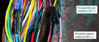
The same option, but when the low beam is turned on, the DRLs go out. In this case, we connect the plus in the same way as in the first option, and the minus – to the positive wire of the low beam lamp (either of the two). The fact is that an incandescent lamp consumes much more current and has a much lower resistance than LED DRLs and therefore, when the DRLs are turned on in this way, the lamp filament will not heat up even to the minimum glow at full incandescence, and when the DRL is operating, the resistance of the lamp filament is ( even warmed up) will have practically no effect.
As soon as you turn on the low beam, a plus will appear on the negative side of the DRLs and they will go out. True, if you turn on the high beam, the DRLs will light up again. In this case, you can connect the DRLs to the side lamps in the same way (if incandescent lamps are used as such, and not LED!). In most cars I know, the side lamps are a priori connected in parallel, so you can connect the common negative wire from two DRL lamps to any side lamp.
Option 3.
This is an option where the DRLs turn on automatically only when the engine is started and running. In this case, we also connect the minus of the DRL to the car body, and the plus to the 30th contact of the relay. Contact 87 is connected to the more powerful positive (you can connect to the positive terminal of the battery), contact 85 of the relay is connected to the vehicle ground through the running lights, and 86 is connected to the reed switch, to one of its terminals.
We also connect the second output of the reed switch to any plus nearby (can be from the generator or from the same place - from the battery). We start the car and by moving the reed switch around the generator we achieve the relay activation and the DRL ignition. We attach the reed switch, pre-packaged in heat shrink, using a plastic clamp to the generator in the found position and you’re done.
Option 4.
If there is no reed switch. Everything is the same, only contact 86 goes to the oil pressure lamp in the instrument panel.
That's all. In conclusion, I will say that using something made with your own hands is much more pleasant than something made by others. Good luck in implementing your and not yours, but most importantly, interesting ideas.
– these are lighting devices installed on a car and intended for use during daylight hours to improve the visibility of the vehicle while driving. DRLs can be provided by the manufacturer or installed additionally.
Daytime running lights on the VAZ-2114 are not provided by the manufacturer, therefore, if there is such a need, they can be installed additionally.
Connection via 5-pin relay
Now it's time to learn how to connect running lights via a five-pin relay. The scheme is the most universal, and was assembled to eliminate the disadvantages of previous options.
First, about connecting the relay for DRLs:
- 30 – to the positive terminals of LED modules;
- 85 – to the positive wire of the side lamp;
- 86 – on the car body;
- 87a – to “+” from the ignition switch;
- 87 – do not connect (isolate).
The circuit with a five-contact relay works as follows. When you turn the key, +12 V is supplied to the DRLs, thereby turning them on. If you turn on the side lights or headlights, the relay will open contact 87a and close inactive contact 87. As a result, the DRLs will go out and the side lights will turn on. The circuit fully complies with the requirements of GOST and traffic regulations and can work with side lights even based on LEDs.
However, the circuit still has one negative point - the DRLs will turn on immediately after turning the ignition switch. That is, if you turn the key in the ignition but do not start the car, the DRLs will light up.
Despite the existing drawback, the circuit is quite successful, but in order to correctly connect the DRL via a five-pin relay, you will need to supplement the circuit with a voltage stabilizer.
This switching option is interesting because the path of current flow through the running lights is independent. This allows you to install light sources of any type and power in headlights and DRLs.
LEDs
How to make a spray gun for whitewashing with your own hands How to make a spray gun with your own hands Types of paint spray guns
There are two options: either buy LEDs and assemble the lamp yourself, or purchase a special design in which the diodes are already installed in an aluminum board.
It is worth noting that it is possible to assemble the lamp yourself, but you need absolute confidence in your actions. LEDs can easily be damaged during installation, and you will have to purchase new ones. If the DRLs are installed incorrectly, there is a possibility of damaging important vehicle systems or harming its appearance. Also, if the running lights do not meet the necessary requirements, the visibility of the car on the road for other drivers is reduced, which can lead to an accident. In addition, homemade DRLs may not have sufficient protection from adverse environmental influences, which will greatly reduce their service life.
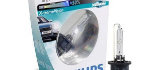
It is better to take light sources from popular manufacturers; these companies most often provide guarantees for their products, and the buyer, if necessary, can always contact the customer service center. The best DRLs are Osram devices, for example, OrsamLed Riving FOG. Philips brand devices have also proven themselves well. If you lack funds, you can use cheaper equipment from Korean manufacturers, for example, Samsung or Seoul Semiconductor, but it is better not to use Chinese diodes, especially those that have a suspiciously low cost.
You can assemble an LED lamp provided that you know exactly what to do
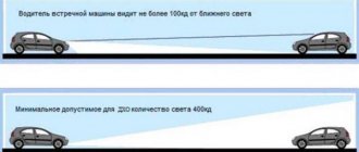
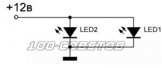
It is recommended to use LEDs with a power of 1-1.2 W; four such elements are enough to create light with an intensity of 400-800 Cd (this is the aperture ratio indicated in official standards). It is worth noting that sometimes three diodes are enough. No more than four elements can be installed in series, this is due to the fact that the circuit is powered by a battery. You can turn on several chains of 4 LEDs in parallel, but this does not make much sense, since the power of one such circuit is quite enough.
After installing the last light bulb, it is necessary to seal all contacts so that they do not collapse under the influence of adverse external factors. Then you need to install the board in place. It is recommended that before turning on the running lights for the first time, you should once again check all connections for any errors or inaccuracies made during installation.