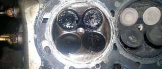
This is an engine part and at the same time the outermost link of the gas distribution mechanism. The valve group includes: a spring, a guide sleeve, a seat, and a spring fastening mechanism. All these parts operate under difficult mechanical and thermal conditions, experiencing enormous loads.
The seat-valve interface is subject to the greatest impact of high temperatures and shock loads. In addition, parts are constantly lacking lubrication due to high operating speeds. This causes them to wear out intensively.
Requirements for the group:
- Tightness of the valve operation in conjunction with the seat;
- High streamlining coefficient when the working mixture enters and exits the combustion chamber;
- Light weight of group parts;
- Parts must be high-strength and at the same time rigid;
- Resistance to high temperatures;
- Efficient heat dissipation of valves;
- High resistance to mechanical and shock loads;
- Anti-corrosion.
Purpose and features of the device
The purpose of the valve is to open and close holes in the cylinder head to release exhaust gases or admit a new working mixture. The main elements of the part include the head and the rod. The transition from the rod to the head serves for smooth removal of gases; the smoother it is, the better the filling or cleaning of the combustion chamber will be.
Exhaust gases leaving the combustion chamber create strong excess pressure, and the smaller the area of the valve plate, the less load it experiences, which is why the engine exhaust valve is made of a smaller diameter and the requirements for it are higher. So, during operation, the exhaust valve head heats up to 800-900°C on gasoline engines and up to 500-700°C on diesel engines, the intake valve heats up to 300°C.
It is for these reasons that in the manufacture of exhaust valves alloys and materials that have increased heat resistance and contain a large number of alloying additives are needed. The valves are made of 2 parts: a head made of heat-resistant material, a rod made of carbon steel. To manufacture an internal combustion engine valve, these blanks are welded and ground.
The exhaust valves, at the point of contact with the cylinder, are coated with hard alloy. The thickness of the alloy is about 1.5-2.5 mm. This coating avoids corrosion.
Due to lower loads, chromium or chromium-nickel steels with medium carbon content are used in the manufacture of intake valves. When the working fluid is introduced into the combustion chamber, the fuel removes some of the temperature from the valve and its components, which is why its temperature differences are lower.
The valve's performance is greatly influenced by its shape. The more streamlined it is, the higher the speed of the incoming or outgoing charge of the mixture. Most often, the valve head is made flat to facilitate the manufacture of the part, reduce the cost of its production and maintain rigidity.
However, in engines experiencing increased loads, for example, forced ones, due to the specifics of the engine itself, intake valves with concave heads are used. This device reduces the mass of the part and the inertial force that occurs during operation.
The valve is connected to the seat along a thin rim on the surface of the cylinder head - a chamfer. The standard chamfer angle for intake valves is 45°, for exhaust valves it is 45° or 30°. When making cylinder heads, the chamfers are ground, and then, when installing the valve, each one is ground to the seat. The width of the rim must be at least 0.8mm.
The rim must not be interrupted around the entire circumference of the valve disc. The joint between the valve and the seat must be sealed for sure, which is why the angle of the valve chamfer, on the outer side of the chamfer, is made smaller than the angle of the seat by 0.5-1°.
In some engines, for greater product safety, a forced valve rotation device is used. During operation, carbon deposits are deposited on the chamfers, the seal is broken, mechanical damage appears, and this sharply reduces the efficiency of the motor. When turning, the internal combustion engine valve distributes the load evenly over the entire surface of the chamfer and forcibly cleans it.
After chamfering the head, the valve has a special belt in the form of a cylinder. This design feature helps protect it from overheating and burning, and also makes the head more rigid. In addition, during grinding, the valve diameter remains the same.
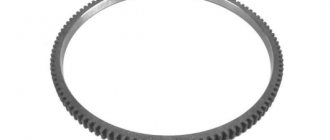
A snap ring prevents the valve from falling into the engine combustion chamber if the shank mounting elements break.
When in contact with the camshaft cam, or rocker arm, the ends of the valve are subjected to heavy loads. Therefore, to give them rigidity and wear resistance, they are hardened, or special caps made of high-strength alloys are put on them.
The intake valves are equipped with special rubber valve stem seals to prevent oil from entering the combustion chamber through the gap during the intake stroke.
Exhaust valves, operating in extreme temperature conditions, can jam in the hole in the guide sleeve. To prevent this from happening, their rods are made of a smaller diameter near the head, compared to the surface along the remaining length.
The nuts that hold the valve springs hold onto the valve itself using fastenings provided by recesses.
The diameter of the exhaust valve stem is larger than the diameter of the intake valve stem, and the valve head is smaller. This design technique allows you to remove more heat from the valve and lower its temperature. However, this technique increases the resistance to gas flow, making combustion chamber cleaning less effective. When calculating, this parameter is difficult to find out, so it is neglected, considering the pressure at the outlet to be greater than the pressure at the inlet, which more than compensates for the shortcoming.
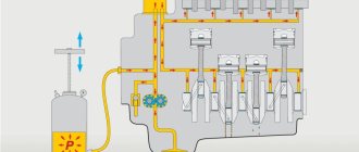
To increase the cooling effect of the exhaust valve, it is made hollow inside. The empty space is filled with a metal with a low melting point, usually liquid sodium. Heating from the valve head, liquid sodium vapor rises to the upper, colder part, taking most of the heat with it. There they come into contact with the less heated part of the rod and transfer heat to it.
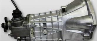
Upper shaft position
Depending on the design of the power unit, the shaft can be located either above the block or inside it. Let's consider the first case first.
Thanks to the upper position of the shaft, other parts are interconnected with cylinders or pushers.
The principle of operation is as follows: what pushes touches the part, which at this time transfers energy to the part, and it manages to rest on the valve leg; it is kept raised by a spring with a different force, that is, it is closed.
In the system described, the camshaft, located at the top of the engine, operates thanks to a drive having gears. It can also be seen that the cams and the pusher device located directly above the two gates are connected to each other.
The pusher pressure exerted on the cam causes the part that holds the valve to relax the spring. Next, when the shaft rotates, the spring moves and falls into place, then the valve closes.
It is this design that allows the engine to operate, which is equipped with an overhead valve mechanism.
Valve springs
The spring operates under heavy loads. Its main task is to create a reliable and tight connection between the valve and the seat. When under load, the spring may break, often due to its resonance. In order to prevent this phenomenon, the spring coils are made with variable pitch.
You can also make a conical or double spring. Double springs have the added benefit of having two parts to increase the reliability of the mechanism and reduce the overall size of the springs.
In order to eliminate the possibility of resonance in the double spring, the direction of the turns of the inner and outer springs is made different. This also allows you to retain fragments of the part; in the event of a spring break, the fragments will be retained between the turns.
Valve springs are made of wire, the material of which is steel. After shaping, the product is hardened and tempered. To increase strength, blow with air with the addition of abrasive material.
To avoid corrosion, the springs are treated with zinc or cadmium oxide. The ends of the springs are ground and given a flat shape. This is done to more effectively fix the ends of the springs with special fixed plates in the cylinder block. The plates are made of low carbon steel; the top plate is fixed to the valve using a cracker.
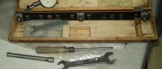
Adjusting the YaMZ 238 valves in two revolutions of the crankshaft.
It consists in the following. As in all the described cases, the piston of the first cylinder is set to TDC at the moment of compression. But it is set more accurately according to the crankshaft marks. The fuel injection pump mark is first aligned, then the mark on the pulley is aligned with “0” on the front cover. And the valves are adjusted according to the diagram
Then the crankshaft rotates one revolution, that is, 360 degrees. The marks of the crankshaft pulley or flywheel are again set to “0” and the following valves are adjusted.
But where does this save a lot of time? It's not entirely clear to me. The crankshaft also rotates two revolutions. Maybe fewer approaches. More precise alignment of the crankshaft is required. Which is also not very profitable. Climb under the car and look for marks that are clogged with dirt or simply cannot be read. And you won’t be able to remember this diagram and keep it in your head until the next adjustment. According to the law of meanness, she will not be at hand at the right moment.
Therefore, it is better to forget this method and never use it. There is less rotation of the shaft, and much more fuss. Due to the abundance of information, valves can simply be confused. Let's leave this method for very smart drivers. Which then will still remake the valves differently. If MMZ for the D 240 engine offers valve adjustment in two turns. Yes, it’s convenient and accurate. Kamaz and YaMZ don’t say anything about this and there’s no point in getting into the weeds. The designers know better. It is important for them that the engine runs for a long time. The motor does not forgive even minor mistakes.
Valve bushings and valve guides
Heat removal from the valve stem and its movement in a reciprocating plane are provided by guide bushings. During operation, the bushings themselves are exposed to high temperatures, washed by hot exhaust gases. When the valve moves back and forth, friction occurs between it and the surface of the sleeve. If there is not enough lubrication, then the friction goes almost dry.
It is for this reason that a number of requirements are applied to the material of the bushings, such as: resistance to wear, high temperatures, and friction. Some compositions of cast iron, aluminum bronze, and ceramics have all the properties necessary to create a part that meets these requirements.
For intake valves, due to the difference in heating temperature, the gaps between the guide sleeve and the rod are made smaller. The lower part of the bushing is made into a cone to prevent the valve from jamming.
Knock during operation
The main malfunction of the valves (not counting burnout) is considered to be a knocking sound on a cold or hot engine. The knocking noise on a cold engine disappears after the temperature rises. When they heat up and expand, the thermal gap closes. Another reason may be the viscosity of the oil, which does not enter the hydraulic compensators in the required volume. Contamination of the oil passages of the compensator can also cause a characteristic knocking noise.
On a hot engine, valves may knock due to low oil pressure in the lubrication system, dirty oil filter or incorrect thermal clearance. Natural wear and tear of parts should also be taken into account. Malfunctions may be in the valve mechanism itself (wear of the spring, guide bushing, hydraulic pushers, etc.).
Recesses for valves (seats)
The durability and proper operation of an internal combustion engine directly depend on the quality of the valve recess. If the valve and seat are connected incorrectly, proper tightness of the combustion chamber will not be ensured, and early engine failure is inevitable. The seats are made directly in the cylinder head, in this case we are talking about cast iron heads. Or they are made plug-in, made of steel, for example, in aluminum heads.
Insert seats are held in the head by pressing or flaring.
Consequences of incorrect thermal clearance
It happens that on a particularly cold day, when the engine is not warmed up, extraneous noise appears: a quiet clicking of metal. Normally, the sound gradually stops as the engine warms up.
If the clicking continues in this state, this is a signal that the thermal gap of one or all valves at once is too large. Such a defect is fraught with not only an unpleasant sound! The valves are forced to remain open for too short a time, which leads to:
- to interruptions in engine operation;
- to a decrease in efficiency;
- to problems starting the engine.
In the worst case, detonation combustion can destroy the engine.
A gap that is smaller than necessary is still a big “evil” for the engine! Heating the cylinder to operating temperature (600-900 degrees Celsius!) expands the metal, eliminating the too small gap.
As a result, efficiency decreases, fuel consumption increases, and the conical chamfers on the valves/seats begin to burn out.
Number of valves in the engine
When it comes to valves, many people ask the question: “how many valves should an engine have?” There is no definite answer; a clear quantity can only be determined by studying the design features of the motor. Considering that in a four-stroke power plant the valve performs the intake and exhaust strokes, this means the minimum number per cylinder is two, one intake and one exhaust.
Modern power plants most often use a design with four valves (two intake and two exhaust) per cylinder. When the valve opens, the fuel mixture is thrown into the resulting hole, or exhaust gases escape. The larger the hole, the more efficient filling or cleaning will be. Accordingly, the efficiency of the motor will also increase.
It is impossible to enlarge the hole by enlarging the valve plate, since its size is limited by the size of the combustion chamber. Therefore, to improve the quality of mixture formation, a larger number of valves are installed per cylinder.
There are schemes in which two, three, and even five valves per cylinder are used. Considering that the filling process is more important for engine operation, the number of intake valves in odd-numbered patterns is always greater.
How often are adjustments made?
Of course, valve adjustment is done when a certain mileage has accumulated, but it is also different for different cars. This information can be found in the instructions. But experienced car enthusiasts advise visiting a service station after every 20-45 thousand kilometers for domestic cars, and 60-100 thousand for foreign cars.
But if you know how valve clearance affects engine performance, you will be able to identify problems yourself in time. If, when the hood is open, the engine makes noise, as if there is a sewing machine, then you need to urgently go to a service station. The second sign is a drop in power - the car does not “pull” as before. In such a situation, you don’t have to wait until the car has covered the allotted mileage; you need to take action as quickly as possible.
The adjustment work itself is very inexpensive and takes about an hour - you have to wait until the engine cools down.
On some cars, adjustment is not made at all - if special hydraulic compensators are used. They themselves provide optimal conditions, and they may only need to be replaced, but this is rare. Hydraulic compensators can be installed on most cars, and you can forget about such adjustments forever.