One of the most popular, especially in everyday life, modes of operation of a multimeter is “diagnosis”. It is with the help of this function that you can find an open circuit or short circuit in the electrical circuit, and this often allows you to quickly diagnose and fix the malfunction.
It was possible to check the integrity of the circuit before using the resistance measurement mode - an ohmmeter. The main difference between dialing is that during measurements, if there is an electrical connection between the tested areas, then, in addition to the readings on the screen, a sound signal is heard - a buzzer, which is where the term dialing or ringing came from.
This sound signal significantly speeds up the verification process, you don’t have to be distracted, look at the screen, and it’s not always convenient, and when you hear the buzzer (or not), you already know the result. This is especially useful for mass measurements, for example, when searching for one specific wire in a bundle.
How to use a multimeter in a car: detailed instructions
Some budget electronic testers do not have a separate dialing mode with a sound alert, but they can also check the integrity of the circuit , but this is not so convenient.
Expert opinion
It-Technology, Electrical power and electronics specialist
Ask questions to the “Specialist for modernization of energy generation systems”
How to ring the wires with your own hands Then measure according to the usual scheme described above and watch the changes in the readings on the screen if there are changes, the circuit is intact. Ask, I'm in touch!
Troubleshooting in a car's electrical circuit
If some component in the car does not work, then first of all you need to check the electrical circuit. There are no particular differences between how to test different wires in different cars with a multimeter, except for the high-voltage cable.
First, make sure that there is voltage in the circuit of the non-working unit:
It must be taken into account that in some areas of the car voltage is supplied only when the ignition key is turned on.
When the voltage check is completed, the current value is checked. The device is switched to ammeter mode, the switch selects a measurement range of up to ten amperes. All vehicle devices must be turned off and the tester must be properly connected to the vehicle's electrical network. To do this, a multimeter is connected between the positive terminal of the battery and the unit being tested. The device screen should display the found current value; it should correspond to the consumption of constantly switched on devices of the machine. If the current value exceeds the norm, a conclusion is drawn about its leakage.
In this case, they begin checking devices that are not included in the standard equipment of the car, and places where wiring is part of moving mechanical components.
Experienced craftsmen identify areas with a drop in current, focusing on the readings of a multimeter with the fuses removed one by one. Then check for sparking at the contacts.
If a misbehaving wire is detected, it is ringed to check its integrity, and then its resistance is measured.
Checking the armored wire
The vehicle's power supply consists of the high-voltage wire of the ignition system. Before testing the power wire with a multimeter, carry out visual diagnostics with the motor running. When lighting candles, the voltage reaches several thousand volts.
Therefore, when high-voltage insulation breaks down, a spark occurs at a distance of three to five millimeters from the damaged area. In this case, if the insulation is damaged, sparking is accompanied by a breakdown to the engine, and the spark plug does not perform its function. If the diagnosis is carried out indoors or on a dark street, then the breakdown is clearly visible. The charge from the faulty area can heat the insulation until it ignites.
The cause of the malfunction may be damage to the contact assembly. In this case, the resistance of the central core increases. During corrosion due to thinning, some of the wires in the harness break, and the high resistance prevents the current from reaching the required level. Voltage, in turn, is not supplied to the electrodes of the spark plugs.
Testing a high-voltage cable is different from testing the wires with a multimeter, because the current in the cable is small. This is due to the very high voltage that passes through the power wire. Therefore, such wires have thick insulation and a small core diameter. In buzzer mode, the multimeter will not distinguish a intact wire from a damaged one.
In this case, the resistance is measured. To begin with, visually inspect the connection of the contact groups. According to statistics, breaks most often occur at contact points.
Then the contacts are cleaned with emery cloth to remove corrosion and the oxidative layer to avoid measurement errors. The multimeter is switched to resistance measurement mode with a measurement range of up to ten kOhms. Hands should not come into contact with wires and contacts. An intact armored train has a resistance from 3.5 kOhm to 10 kOhm. In any case, it is best to find the resistance data in the technical documentation and compare with the received ones. The difference should not be more than ten percent.
Directly during measurement, when the cable is twisted, stretched or bent, the resistance should not “jump”.
It is best to test any wires or harnesses, especially in a car, if an electrical and circuit diagram is present. Otherwise, it is difficult to figure out which wire is located in the harness.
After learning the basics of measuring with a multimeter and mastering the method of elimination, anyone can independently diagnose and repair a fault in the wires.
General information
You don't need to be a professional electrician to find a wire break. It is enough to have a measuring device - a multimeter . A multimeter is a multifunctional measuring instrument with its own voltage source. The device can measure the voltage in the circuit, the magnitude of the current and the resistance value. Many multimeters are used to test the continuity of a connection in a circuit.
If a connection is found, then if there is a built-in speaker, the device emits a sound signal. This is where the term “call” comes from. The device rings if there is a connection. A multimeter can also indicate that there is no connection between elements and helps determine a short circuit. Using the tester, all kinds of radio components are checked: resistors, transistors, diodes, relays, capacitors, and so on.
Conductor continuity is based on Ohm's law for a section of an electrical circuit. Ohm's law states that the resistance of an element is equal to the ratio of the applied voltage to the magnitude of the current in a section of the electrical network. Resistance is measured in Ohms. A resistance of one Ohm indicates that a current equal to one Ampere flows through the conductor at a given voltage of one Volt. Based on the calculated data on resistance, conclusions are drawn about the results of the call.
That is, a certain voltage is set on the multimeter, and the current value is determined using the instrument scale and the resistance is calculated. In other words, the multimeter is a voltage source and an ammeter to measure the resulting current.
How to test wires with a multimeter
The most convenient, understandable and safe way to diagnose wires for continuity or short circuit is to check with a multimeter. There are a large number of multifunctional devices with different parameters and prices: from the simplest and most affordable to the more expensive, accurate and functional. But with almost any multimeter you can check the integrity of the conductors; you don’t have to have expensive equipment for this.
What should the multimeter readings be?
There are two methods of checking using such a device: in resistance measurement mode and in continuity mode.
The dialing mode is the most convenient testing method. Here you do not need to have any knowledge of the instrument readings. It is enough to connect the probes of the device to the ends of the cable and hear the sound. In order, the procedure is as follows:
- Turn on the multimeter, set the dialing mode (an icon of several brackets of different sizes, similar to the Wi-Fi designation);
- Connect one probe to one end of the conductor being tested, the second probe to the other end of the same wire;
- If you hear a sound, it means the cable is intact. If there is no sound, there is a break in the line (or the probes are connected incorrectly).
It should be noted that in this way the presence of a short circuit in adjacent conductors is also checked. The only difference is that one probe is connected to the first conductor, and the second probe to the second: if there is sound, there is a short circuit.
The resistance measurement mode is somewhat more complicated. But if you remember what readings should be on the multimeter in different situations, it will be much easier. Moreover, many multimeters do not have a continuity mode, but there is almost always a resistance measurement mode.
The procedure for such a measurement will be as follows:
- Turn on the device, set the switch to resistance measurement mode, set the minimum value for measurement (usually 200 Ohms);
- Connect the probes to the conductor;
- If the display shows any value or zero, then the conductor is intact. If you see the number 1 on the screen, it means the resistance is infinite, that is, the cable is broken.
Reverse sequence for determining a short circuit between conductors or ground: with infinite resistance, the insulation between the conductors is not broken, and the presence of at least some resistance will mean a short circuit.
If you are confident in the integrity of the cable, then in this way you can identify the ends of the same conductor in a bundle of wires with the same color marking. It is enough to connect the probe to the conductor on one side, and on the other hand, alternately lean the probe against each conductor in the bundle. When the signal sounds, you have found the other end of the wire. That's all, nothing could be simpler.
Continuity of a long conductor
To test a wire whose ends are far away and there is no way to reach from the beginning to the end of the wire with two multimeter probes, you can use known wires or ground. For example, a cable may have a colored core, then all the white wires can be called out by connecting it to the white ones at one end and searching for this pair at the other.
If this is not possible, you can use grounding. We connect the wire core to the ground at one end, and at the other we look for a conductor sitting on the ground
It is important here that the grounding is reliable at both ends, otherwise it will not be possible to ring the wire in this way.
Device structure
Devices may differ in appearance, but multimeters are fundamentally divided into analog devices and digital devices.
Analogue devices are already gradually being replaced from the market by digital ones, but in the homes of many home craftsmen you can still find analog devices.
Such devices are equipped with an indicator screen with a scale and arrow. The advantage of these models is the clarity of display of measurements. The deflection of the needle is visually easier to assess than the flashing of numbers on the electronic display of digital instruments. Often, when making a call, it is necessary to evaluate approximate resistance indicators or, in general, its presence or presence, so analog devices are suitable for most practical work.
Digital multimeters have more complex electronics and a digital display. This type of device is used mainly in production and industry.
The housings of all multimeters have outputs for two probes. These are two insulated wires ending in needle-like metal tips. In some cases, special clips, so-called “crocodiles,” are put on the nozzles. When choosing a device, you need to pay special attention to the quality of the probes. The correctness of measurements depends on them.
The wires must be flexible with strong soldering and fit well into the device sockets. It often happens that outwardly spectacular probes are of unsatisfactory quality and have poor technical characteristics.
Checking the electric heating element
You can also ring an electric water heating element with a multimeter. To do this, the probes of the device must be attached to the contact plates of the heating element. If the resistance reading is small, then the heating element is working. With very large values or one (depending on the model), the heating element is damaged and requires replacement.
Note! Sometimes one housing may contain two heating elements connected to voltage in parallel. In this case, you need to ring them separately, having first removed the jumper between them
It is very important for boilers and other water heating devices to ring the contacts of the heating element for penetration into the body. To do this, the probe is connected to one of the contacts, and the second - to the body of the heating device
If the tester shows a certain value, the internal insulation has been damaged in this heating element. To prevent electric shock, the heating element must be replaced.
High-voltage wires VAZ 2115
Automotive high-voltage (HV) wires play an important role for internal combustion engines, since they help transmit high current from the ignition coil to the spark plugs. The serviceability and efficiency of the wires determines the timeliness and intensity of ignition of the fuel-air mixture, and therefore the correct and uninterrupted operation of the engine. Despite their simplicity, wires have many different “sores” and can cause a lot of troubles to their owner, which in one way or another will affect his nerves and pocket.
Connection
The order of connecting high-voltage wires must be strictly sequential, since each cylinder of the engine corresponds to a specific socket on the ignition module. Considering that there is a numbering of the sockets on the ignition module body, the risk of confusing anything is minimal.
The procedure for connecting high-voltage wires of the VAZ 2114 injection type depends on the year of manufacture of your car. Fourteen cars before 2004 had 4-pin ignition modules installed, and cars after 2004 had 3-pin coils.
The connection diagram for VAZ 2114 high-voltage wires to the ignition module (until 2004) is as follows:
Connection diagram for VAZ-2114 with ignition coils (after 2004):
In the pictures you can see the numbers of the landing slots. Each number must have a corresponding cylinder connected to it (cylinder numbering is counted from left to right).
To correctly install high-voltage wires on the VAZ 2114, follow the following algorithm of actions:
— Turn off the ignition. Open the hood and remove the power terminals from the battery;
— We remove the old GDPs from the mounting sockets on the module and cylinders;
— We remember the location of the high-voltage wires of the VAZ 2114 and connect new GDPs according to the diagram. Before replacing, it would not be amiss to draw this very diagram by hand on paper so as not to confuse anything;
— We connect power to the battery and, to check whether we did everything correctly, start the engine.
When installing the wiring, do not try to connect individual air intakes to each other with plastic clamps; to do this, you must use the comb holder that comes with them. A thin clamp can easily wear through the insulating coating. Also make sure that the GDP does not bend.
Connecting armored wires on VAZ 2115 and 2113 is carried out in a similar way.
How to remove high-voltage wires?
Turn off the ignition. Open the hood. Pull out the wires from the ignition module and from the engine.
How to connect high voltage wires?
The BB wires must be connected in a certain order. Each wire goes to a specific cylinder and to a specific connector in the ignition module (ignition coil). There are markings both on the wires and on the ignition module. But without removing the module, the markings cannot be seen, so see the photo below.
Connection diagram for high-voltage wires:
Cylinder numbering from left to right. Ignition module numbering: first cylinder - lower left compartment of the ignition module
Second cylinder - upper left compartment
The third cylinder is the upper right,
The fourth cylinder is the lower right compartment of the ignition module.
Location
Incorrect installation and location of high-voltage wires can lead to a spark jumping from wire to wire or to ground, which, in turn, can lead to misfires and a decrease in the crankshaft speed when the car is moving at high speed.
Therefore, install the high voltage wires properly as shown in the pictures above.
Disconnect the high-voltage wires from the spark plugs and ignition coils. Clean and check the integrity of the insulation of high-voltage wires. Check the internal contact surfaces of high-voltage wires for corrosion or carbon deposits.
Use an ohmmeter to measure the resistance of the high-voltage wires.
How to check wiring
You can diagnose electrical equipment using a voltmeter, ohmmeter or multimeter, or special diagnostic stands. Computer diagnostics are also carried out, during which error codes and main indicators of the machine’s on-board network are read. To independently check circuits and troubleshoot electrical faults, one multimeter or signal lamp is enough.
We use a multimeter
Fuses in the on-board network are considered the “weakest” link in terms of durability. In case of emergency situations (for example, in the event of a short circuit), the safety elements “take the blow”, protecting the rest of the electrics and electrical equipment of the machine. Fuses cannot be restored and must be replaced during repairs.
Checking the voltage
Before checking the wiring in the car, it is necessary to measure the voltage of the electrical circuit between individual components and electrical equipment. You can call like this:
- Set the multimeter to voltmeter mode.
- Connect one probe of the measuring device to the “minus” of the battery or to the ground of the machine.
- Connect the second probe to the supply wire of the circuit.
If a certain value appears on the device display, then there is voltage in this section of the electrical circuit. You can compare the values with those required according to the vehicle's owner's manual.
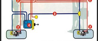
Looking for a short circuit
After measuring the voltage, search for short circuits. This will require either a multimeter or a pilot light. As for the lamp, if the wiring is in good condition and there is no short circuit, it should not light up.
A short circuit in the wiring, as well as a lack of voltage (zero or infinite resistance in the electrical circuit), indicates a malfunction in one of 2 components:
- Consumer - electrical equipment, devices, fuses, blocks.
- Wiring – broken or shorted wires, poor wiring contacts at the point of connection with the consumer.
Checking for a short circuit can also be done in voltmeter mode. To do this, it is necessary to remove all fuses in the area being tested and connect the probe to the terminals of the fuse element. The value “0” on the screen indicates the presence of a short circuit in the circuit. If, when you try to move the wires, voltage appears in the circuit, then the short circuit is caused by the wiring and the wires will need to be replaced.
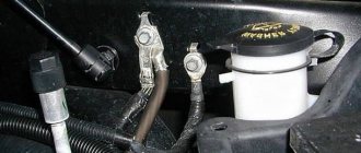
Checking the quality of grounding
Cars use a single-wire wiring diagram - this means that the “minus” goes to the ground (body) of the car. However, corrosion of metal parts, their oxidation and destruction, “loosening” lead to grounding failure and, as a consequence, to disruption of on-board circuit contacts.
Checking the grounding, as well as other electrical elements of the car, is carried out using a multimeter. The procedure is as follows:
- Disconnecting the battery.
- Connecting one multimeter probe to the body (metal parts) of the car.
- Connecting the second probe to the grounding element or wiring connection.
The value displayed on the device screen should be compared with the factory data (car operating manual). If the values diverge greatly, then it is necessary to restore the grounding - clean the metal at the connection point, check the reliability of the fastening.
Checking the integrity of the circuit
The connection of wires in the electrical circuit of cars is one of the most vulnerable points in the entire electrical system of the car. In addition to the destruction of insulation, loss of integrity and breaks at the connection points, oxidation of the contacts also often occurs here. Defects can be determined not only using a measuring device, but also visually. If the integrity of the circuit is broken precisely at the connection point, then soldering of wires with connectors will be required. Otherwise, you need to find the damaged area, which will require a signal lamp or multimeter.
Safety requirements
When performing any inspections of live electrical networks, safety requirements must be followed. You cannot work without protective insulated shoes, and it is also better to wear rubber gloves. When checking the integrity and insulation resistance of electrical circuits, it is necessary to de-energize the network by turning off the circuit breakers, so all checks should be carried out during daylight hours, since with emergency lighting and the light of lanterns you can only work in case of an emergency.
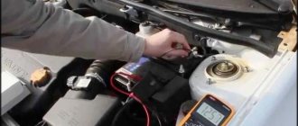
Multimeter and battery
It happens that the incorrect functionality of the battery is obvious. A multimeter comes to the rescue here too. Having picked it up and set it up to measure current, you need to:
First we disconnect one terminal, then we connect the red contact to the positive value. Accordingly, black goes to minus. A normal voltage reading is considered to be between 12.4 and 12.8 V.
Remember! Measurements are taken no earlier than an hour after the engine is turned off.
You still need to measure the voltage under load. This means that it should be equal to a figure twice as large as the capacity.
This means that if the capacity is, say, seventy-five A/hour, the corresponding load should be one hundred and fifty amperes. A voltage drop below nine indicates a battery malfunction. This may also indicate that the battery is undercharged. When you disconnect the load, the voltage usually returns to normal within seven seconds.
By the way, it is better to carry out wiring diagnostics armed with a diagram of the electrical equipment of your car.
How to test a car battery with a multimeter
Testing a car battery with a multimeter involves connecting two probes at once. Also turn off the engine before taking measurements.
Place the red probe against the “positive” terminal, the black one against the “negative” terminal. If you mix it up, it’s okay, the device will show the current numbers, just with a minus sign.
Look at the device screen. The normal battery charge ranges from 12.6 to 12.9 volts.
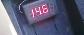
The operation of the battery can also be checked with the engine running. When checking the car battery with a multimeter, you will also find out how the battery works in conjunction with the generator, as well as whether the voltage regulator is working properly.
Normal numbers with the engine running are 13-14 volts. If the multimeter shows less, the battery needs to be charged, or there is a current leak.
Remember: a multimeter will show the battery charge, but will not tell you everything about its operation. There are other devices for this. For example, a load fork.
How to check car sensors with a multimeter
The reason for the “death” of the battery, voltage surges, and unnecessary values on the instrument panel can be various sensors in the car. According to the experience of motorists, 5 types of sensors most often cause problems:
You can understand where they are located from the instructions for the car, on car enthusiast websites, and various forums.
To check your car's sensors with a multimeter, you will also need information about the normal voltage readings specifically for your car. It can also be found in the instructions or on the Internet.
What should be the resistance of high-voltage ignition wires?
In order to obtain the most complete information about the serviceability or malfunction of a high-voltage wire, a method of measuring its physical parameters is used.
The simplest electrical measuring tool that should be in the trunk of any car is a multimeter. A simple small multimeter made in China is a little larger than two matchboxes in size and costs about 300 rubles.
In high voltage wires, two main parameters are checked: the resistance of the current-carrying conductor
and
insulation resistance
. The second parameter cannot be measured using a conventional multimeter; for this you need to have an expensive megohmmeter, since the insulation resistance must be several hundred megohms.
The resistance of the center conductor should be in the range from zero to several kiloohms. This depends on the type of high-voltage wires and the presence of limiting resistance in the ignition system.
Limiting resistances began to be used when cars began to be equipped with radio receivers. They significantly reduce the level of radio interference. In addition, they have another important function of protecting the ignition coil and control circuit from breakdown in the event of an overload in the high-voltage circuit. This is possible if the spark plug has a short-circuiting deposit, as well as if a high-voltage wire breaks down on the car body.
In many cars, limiting resistances are placed in a slider; in some cars, spark plugs have a limiting resistor. Sometimes resistors are inserted into the spark plug caps. But most cars use distributed resistance inside high-voltage wires.
In other words, the current-carrying core of a high-voltage wire is made of a conductor with high resistivity:
- nichrome, an alloy of nickel and chromium;
- cotton threads impregnated with a soot solution with a resistance of about 20 kOhm/meter;
- polymer conductive material with a resistance of about 15 kOhm/meter;
- fiberglass coated with graphite.
Sometimes such a conductor has the shape of a spiral, as in electric stoves.
To check high-voltage wires, the multimeter must be switched to resistance measurement mode at a limit of 20 kOhm. Next, connect the probes of the device to the opposite terminals of the wire.
The measured resistance should not exceed a resistance of 20 kiloohms (usually this value ranges from 500 to 3000 ohms). For ignition wires with distributed resistance, its value depends on the length of the high-voltage cable.
Operating principle
The analog type of the device does not require its own power supply . Its operating principle is the same as that of an ammeter, and an analog device works best in the range of radio waves and electromagnetic fields. There are induction coils inside the device body, and when the probes touch the conductor, a current begins to form in the coils. The created magnetic field deflects the indicator needle to a certain angle. The magnitude of this angle depends on the strength of the current generated, and the arrow on the drawn scale indicates the measurement value.
Digital devices contain a textolite printed circuit board on which a digital chip , which is responsible for processing the received data. To operate the electrical circuit and screen, digital devices are powered by batteries or an external power source.
Digital multimeters have lower measurement uncertainty and are more accurate than their analog counterparts.
There is a switch on the front panel of the multimeter that selects the measurement mode. The switch sets the scale factor that determines the value on the device scale.
Analog instruments have two types of scale:
- Uniform display.
- Logarithmic exponents.
The uniform scale is very sensitive to overloads, so the switch is first set to a large scale factor value, which is gradually reduced. The logarithmic scale does not have this drawback and has a range of values from zero to infinity.
Thus, the main components of multimeters are:
- Display for showing measured values.
- Connectors for probes and probes themselves.
- Switch for different modes and ranges.
Rules for using the dialer
The only rule that needs to be remembered is that the dialing process is allowed only in a completely de-energized circuit.
Note! If you check live wires, you can get an electric shock and, in some cases, cause a fire. Below we describe in detail how to check the wire with and without a multimeter. Below we describe in detail how to check the wire with and without a multimeter
Below we describe in detail how to check the wire with and without a multimeter.
How to properly test wires (with a multimeter and without instruments)
Step-by-step work process:
- before starting work, you must turn the multimeter handle to the desired position;
- connect the ends of the probes to the required sockets. The black probe goes into the socket marked COM (in some cases indicated as “*” or ground point), and the red one goes into the socket marked Ω (sometimes indicated as R). It must be emphasized that the symbol Ω can be drawn either alone or in combination with the designations of other signs (V, mA). This arrangement of wires will help maintain polarity when making future measurements;
How to connect probes
- turn on the multimeter. Basically, there is a separate button for this or work can start automatically when the handle is turned to the required position;
- close the measuring ends to each other. If a beep is heard, the device is working correctly;
- take the wire to be tested (strip it of insulation in advance). Touch the exposed parts of the cable with measuring probes;
- If it is working properly, a sound will sound and the multimeter readings will be zero or show resistance. If the screen shows 1 and there are no sounds, it means that the tested cable is broken.
You can ring the wires without using a multimeter. To work you will need:
Diagram of a device with a light bulb
- a classic battery (it is advisable to take a 4.5-volt square battery);
- a regular 4-volt light bulb, through which the linear section of the cable is diagnosed (monitored);
- A pair of jumper cables and a breathtaking looking connector.
After preparing the tools for work, you need to use them to assemble a simple measuring circuit. If the circuit is correctly assembled and the wire is in good condition, the lamp will work. If there is a defect in the area, the light will not light up.
What is a short circuit? Its consequences
Short circuit occurs in sockets, plugs, junction boxes and other places where there is a connection of wires. The reason for everything is poor quality contact. It leads to an increase in load and, as a result, to heating. Most often, the result is burnout of the insulation, as a result of which the supply wires become short-circuited with each other.
A short circuit is very dangerous for humans and in most cases causes a fire. In this regard, it is necessary to determine its location quite quickly.
In order to prevent short circuits, it is necessary to periodically test the power cable lines with voltage, which will avoid serious consequences.
How to check wiring
You can diagnose electrical equipment using a voltmeter, ohmmeter or multimeter, or special diagnostic stands. Computer diagnostics are also carried out, during which error codes and main indicators of the machine’s on-board network are read. To independently check circuits and troubleshoot electrical faults, one multimeter or signal lamp is enough.
We use a multimeter
Fuses in the on-board network are considered the “weakest” link in terms of durability. In case of emergency situations (for example, in the event of a short circuit), the safety elements “take the blow”, protecting the rest of the electrics and electrical equipment of the machine. Fuses cannot be restored and must be replaced during repairs.
Checking the voltage
Before checking the wiring in the car, it is necessary to measure the voltage of the electrical circuit between individual components and electrical equipment. You can call like this:
- Set the multimeter to voltmeter mode.
- Connect one probe of the measuring device to the “minus” of the battery or to the ground of the machine.
- Connect the second probe to the supply wire of the circuit.
If a certain value appears on the device display, then there is voltage in this section of the electrical circuit. You can compare the values with those required according to the vehicle's owner's manual.
Looking for a short circuit
After measuring the voltage, search for short circuits. This will require either a multimeter or a pilot light. As for the lamp, if the wiring is in good condition and there is no short circuit, it should not light up.
A short circuit in the wiring, as well as a lack of voltage (zero or infinite resistance in the electrical circuit), indicates a malfunction in one of 2 components:
- Consumer - electrical equipment, devices, fuses, blocks.
- Wiring – broken or shorted wires, poor wiring contacts at the point of connection with the consumer.
Checking for a short circuit can also be done in voltmeter mode. To do this, it is necessary to remove all fuses in the area being tested and connect the probe to the terminals of the fuse element. The value “0” on the screen indicates the presence of a short circuit in the circuit. If, when you try to move the wires, voltage appears in the circuit, then the short circuit is caused by the wiring and the wires will need to be replaced.
Checking the quality of grounding
Cars use a single-wire wiring diagram - this means that the “minus” goes to the ground (body) of the car. However, corrosion of metal parts, their oxidation and destruction, “loosening” lead to grounding failure and, as a consequence, to disruption of on-board circuit contacts.
Checking the grounding, as well as other electrical elements of the car, is carried out using a multimeter. The procedure is as follows:
- Disconnecting the battery.
- Connecting one multimeter probe to the body (metal parts) of the car.
- Connecting the second probe to the grounding element or wiring connection.
The value displayed on the device screen should be compared with the factory data (car operating manual). If the values diverge greatly, then it is necessary to restore the grounding - clean the metal at the connection point, check the reliability of the fastening.
Checking the integrity of the circuit
The connection of wires in the electrical circuit of cars is one of the most vulnerable points in the entire electrical system of the car. In addition to the destruction of insulation, loss of integrity and breaks at the connection points, oxidation of the contacts also often occurs here. Defects can be determined not only using a measuring device, but also visually. If the integrity of the circuit is broken precisely at the connection point, then soldering of wires with connectors will be required. Otherwise, you need to find the damaged area, which will require a signal lamp or multimeter.
Features of automotive wiring
Indeed, all these wiring harnesses that encircle the car from top to bottom perform the only task - to ensure the uninterrupted transmission of electrical impulses between the components of a particular system. And if one of the wires has poor contact, or even worse, the terminal is burnt out or oxidized, then the operation of the circuit will be disrupted or even fail.
Replacement is simple; it’s more difficult to find the location of a break or short circuit with your own hands, especially if you don’t know how to do it.
In this article we will try to answer many questions, including:
- how to test the wiring in a car to find a fault;
- how to properly repair the actuator;
- how to restore bad contact;
- how to solve other electrical problems.
Troubleshooting wiring requires basic knowledge and precise tools.
What's under the hood
In the engine compartment there are many wires that perform a wide variety of functions:
- transmitting high voltage pulses from a current source (generator or battery) to the engine cylinders;
- transmitting data from various sensors;
- ensuring continuous operation of the fuel supply system, lighting fixtures, etc.
The wiring of the ignition system deserves the greatest control.
What's in the cabin
Inside the car, intended for the driver and his passengers, there are even more wires, since there are:
- Automotive system controls:
- control of external lighting devices (road lighting, maneuvering signals and rear brake lights);
- management of audio devices;
- automatic transmission control;
- control of electronic assistants (cruise control, automatic windshield wipers, navigation system);
- Control devices and sensors;
- Active safety systems:
- electric seat belts;
- driver and front passenger airbag mechanisms;
- Comfort features:
- air conditioner;
- window regulators;
- musical equipment;
- heating systems for windows, mirrors, seats, etc.
Replacing the wiring in a car will necessarily require disassembling the instrument panel.
Note! Wiring harnesses run through the interior to the rear of the car. Therefore, there is a maximum concentration of electrical wiring inside the machine.
We check the wiring in the apartment with a multimeter
Let's take as an example a modern apartment in which the wiring is done in accordance with current requirements and standards. This means that when laying the lighting lines and power outlets, they were separated, and separate wires were laid for them in each of the rooms. Each of these circuits is powered from the apartment panel through a separate circuit breaker.
If the light has gone out in one of the rooms, you should first check that the lamp is working properly. Before starting work, it is necessary to turn off the power to the room/apartment depending on the power supply. When using an opaque incandescent lamp in a lamp, the integrity of the filament is difficult to visually determine, so you will need a multimeter and its continuity function. Let's figure out step by step how to do this correctly.
First you need to check the shield for triggered circuit breakers. In the first case, they will be in the on position (then the fault may be hidden in the room switch, lamp or socket). The likelihood of damage to the wiring in such a situation is low. If the device works, you will need to check everything except the room switch, including the switchboard itself.
If the machines don't work
We ring the switch. When the switch is on, there should be a sound signal, when off, there should be silence and “1” on the indicator.
- Make sure there is voltage at the input and output of the machine. If it is, you can proceed to further verification.
- Prepare the device for operation and check its serviceability by short-circuiting the measuring leads.
- Unscrew the lamp from the socket.
- Touch one of the measuring probes to the base (the metal part of the lamp with threads), and the second to the central contact of the lamp (the insulated center of the end part of the base).
- A sound signal and instrument readings that are different from 0 or 1 mean that the lamp is working. If it is faulty, you need to replace it, which will solve the problem.
- We check the cartridge for serviceability. To do this, you need to disassemble the lamp, make sure that the connected wires and contacts are intact. If everything is in order, then the cause of the failure is not in the cartridge. If malfunctions are detected, they must be eliminated. The lamp cannot be screwed in yet.
- We check the serviceability of the room switch. To do this, remove the plastic cover, unscrew the screws and take it out of the mounting box. We inspect the equipment for the appearance of carbon deposits and check the tightness of the fasteners. If everything is in order, you need to install the measuring ends of the tester on the contacts of the switch. The appearance of a sound signal when dialing in the on position will indicate that the equipment is working properly. The wires do not need to be disconnected.
During such a check, as a rule, a malfunction is identified, which becomes the cause of all the troubles. Eliminating it allows you to quickly solve the problem.
If the machine worked
To ensure electrical safety during work, in this case the voltage is turned off using a general apartment circuit breaker. Next, the serviceability of the socket and the wires connected to the lamp is determined according to the algorithm described above. If there are no faults, you need to check the wiring itself using a multimeter and the continuity function. Such malfunctions happen quite rarely, but they still happen, for example, when installing suspended ceilings or decorative interior elements.
The wiring in this case is performed as follows.
- Using a screwdriver, disconnect the connected conductor (if installed correctly, it is located at the bottom) and move it to the side. The “zero” of this group is, as a rule, located at the zero clamp under the machines.
- Unscrew the incandescent lamp from the socket. Using a ready-to-use tester, we check the line by connecting one of the measuring probes to “zero” and the other to the disconnected conductor. If the device beeps, it means the wiring is shorted.
- In this case, in the room under the ceiling above the switch, we find and open the junction box. We disconnect the wires.
- We check all groups of wires for short circuits. To determine the section of the circuit in which there is a short circuit, we again check the circuits on the apartment panel with a multimeter. If the signal sounds, it means that it is the wire laid from the switchboard to the box in the room that needs to be repaired. Otherwise, the search will need to be continued until a result is obtained.
Trailer Raccoon: technical specifications, price, where to buy
- The switch can be placed in any position in the zone;
- A suitable measurement range is selected;
- Before the operation, the power supply must be turned off;
- Otherwise, the tester will not show the correct value;
- If you see the number 1 on the display, or the values Over and Ol, then you should set a higher range;
- Otherwise, overload will occur;
- When 0 appears, the tester is transferred to a smaller range.
Following these simple rules and consistency in your actions will allow you to quickly and without any problems carry out all the necessary procedures for measuring resistance.
A good multimeter function that often comes in handy when repairing home appliances. For example, I recently fixed my wife’s iron. And the tester turned out to be extremely useful in this work.
Calling
I didn't tell you anything about the back panel of the multimeter. Although there are several more functions there. They are mainly intended for radio technicians who are professional in their work. They will not be needed for tasks at home or when repairing a car.