In VAZ-2107 cars, connecting a door sensor couldn’t be easier: there is one wire that is shorted to ground when any door is open. The cord from the handbrake sensor is routed to the “tidy”, and in the adjacent connector there is a tachometer contact. In general, the owner can install a “regular” alarm system that does not have auto start without any help. A more complex option, when connected to the ignition switch, is also discussed in our text. In the first case, by the way, you can use the turbo timer. Let's start considering this option right now.
Features of standard electrical wiring
First you need to clarify what exactly needs to be connected if the installation is performed without autorun:
- Ignition control;
- Power supply for the alarm itself;
- Door switches;
- Handbrake switch;
- Signal lamps (2 wires).
As you can see, the number of elements here is kept to a minimum. But even using this, that is, a minimum set of points, will allow you to quickly connect a turbo timer. Simply, in cars of the 2107 family, the ignition support relay is installed as standard. And you need to use this.
Look at the diagram and you will understand what we are talking about:
Elements of standard car wiring
In general, the figure shows all the important elements:
- Ignition support relay.
- Outputs for light signaling (blue and black-blue). The 8-pin connector is located in the steering column.
- Door control wire. It is located in the side tunnel near the clutch pedal.
Make T-branches and connect any signaling. By the way, the power supply to the lamps (second photo) is connected through fuses. Which is true for any car, not just the VAZ-2107.
Installation points for any alarms in classic VAZ cars: model 2107
In VAZ-2107 cars, connecting a door sensor couldn’t be easier: there is one wire that is shorted to ground when any door is open. The cord from the handbrake sensor is routed to the “tidy”, and in the adjacent connector there is a tachometer contact. In general, the owner can install a “regular” alarm system that does not have auto start without any help. A more complex option, when connected to the ignition switch, is also discussed in our text. In the first case, by the way, you can use the turbo timer. Let's start considering this option right now.
How to use the ignition switch
Any alarm equipped with auto-start is usually equipped with 5 power terminals:
Basic connection diagram
Cord 3 here is the control one; it is connected to the starter terminal. And on the blue wire, that is, on terminal 15/2, the voltage may disappear when the starter is running, or it may remain on it all the time. When setting up, select one option.
VAZ 2101-2107 cars have their own characteristics. The coil of the additional relay shown in the diagram cannot be connected to the ignition cord going to the standard relay. The line is simply not designed for additional load!
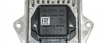
Let's see what the ignition switch looks like in reality:
Terminal block of standard lock
If you really need autostart, the starter cord (red) will have to be cut. Let's list what the correspondence between the lock and alarm cords looks like. The alarm cable will be indicated on the left:
- Green – free;
- Blue – free;
- Red – pink;
- Black-yellow thick – red (tap to starter);
- Black-yellow thin – red (bend to the lock);
- Yellow - blue thick.
In theory, everything turns out simple.
Of course, you can install the autostart system yourself. But it is better to entrust this task to a professional electrician. The three cords leading to the alarm must carry significant current. In new VAZ models the number of these cords will be no less.
Handbrake control
The dashboard diagram of the VAZ Seven looks like this:
Internal wiring diagram
The cord from the handbrake limit switch goes to terminal 8 (connector X2). Connect to this contact unless the instructions indicate that a diode must be installed. Otherwise, use terminal 4.
Connecting to the 4th terminal if the diode is not specified in the basic diagram is incorrect. Remember this and be careful.
Didn't find the information you are looking for? on our forum.
Installation and connection of additional elements
Many cars do not have hood, trunk, or fuel filler door sensors. You can purchase limit switches, connect them in parallel and connect them to the control input. This is how, for example, they install the hood button:
Installation of the sensor-button
One subtlety must be taken into account - the “open” position must correspond to a closed state. Installation is carried out in the following sequence:
- Secure the switch body;
- Additional wires are passed through the seal where the hydraulic corrector tubes pass;
- Connect the sensor, and at the same time the siren.
Now let’s add movement control to the car, that is, the alarm will “know” whether the car is actually moving.
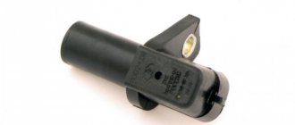
Connecting to the speed sensor
Let's talk about the "Seven" with an injection engine. Then the speed sensor is installed and connected from the factory. It will be easy to find the contact of this sensor:
ECU connection diagram
As you can see, you need to make a tap connected to one ECU terminal (1/59). Here we are talking about the control unit, that is, the standard engine controller.
Not every alarm system has a separate input connected to the speed sensor. But if the connection is still made, take care of good contact with ground. Under the “dashboard” there are two copper studs connected to the body. One of them is located near the ECU, and it is better to connect to it (see figure).
Ground connection point
It would seem that the speed sensor is a fairly simple additional device. And if this element is missing, you can buy it and install it yourself:
Pulse sensor
The sensor housing must cover the hole in the gearbox housing. Everything looks simple, and you can do the installation yourself, but the tightness of the assembly will then be broken. In general, it's better not to take risks.
Subtleties of engine control
If autostart is not used, the alarm should not read data from the engine. Otherwise, it is necessary to implement control that allows you to turn off the starter at the right time. The control itself is usually carried out like this:
- The signal can read the value of the supply voltage;
- The cord from the generator is connected to the terminal of the VAZ-2107 tidy - the control cable can be connected to this terminal;
- It is best to control the launch using the tachometer, for which the alarm will still need to be configured.
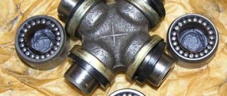
The third option is preferable. The cord is not connected directly to the tachometer terminal, but through a capacitor and resistor:
Generator and tachometer outputs
Direct connection is used for “generator” control.
In practice, only one control method can be used. First, installation and connection are performed, then the system is configured.
FakeHeader
Comments 17
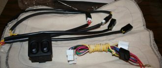
Heavy hehehehe. The corrugation is not for this car, you need to install rubber tubes that are specially designed for classics.
The actuator connector had to be cut off, twisted, ideally, soldered again... And the rods had to be wrapped with foam rubber so as not to rattle)...
PS: So I understand, the car is not yours, let the owner deal with this... For a couple of seconds. could have been done, of course, for an additional fee. fee).
The power of the actuators is not enough because the bimetal wiring is laid with a real cross-section of less than 0.7. This is called hack work. These wires are not even tinned. It's been like a year. I have already replaced the wiring for myself and my friends to 1.5 kV. The actuators fire even on a dead battery. Previously there were constant problems. Including periodic failures of actuators in different doors
I will not argue. Perhaps the wiring is bad, but this problem occurs even in cars with factory central locking (VAZ 2110 and modifications). And all problems were solved by removing the springs.
The exact definition of this action is “crutches”. By the way, I don’t have them either, since at one time I solved the problem along the path of least resistance. In the end, I had to do it for myself once and for all
It is better to install corrugations straight. These S-ki quickly dry out and crack, and they are compressed when the door is closed. Now just a classic in the works. True, I had to install two rubber bands, there are a lot of wires (activator, ESP, heated mirrors, speaker).
Basically, all rubber bands dry out and crack.
Corrugations are faster because they work in torsion all the time
It is better to install corrugations straight. These S-ki quickly dry out and crack, and they are compressed when the door is closed. Now just a classic in the works. True, I had to install two rubber bands, there are a lot of wires (activator, ESP, heated mirrors, speaker).
What exactly are these rubber bands called?
Strange ! Alarm? Are they being stolen? According to my Classic Wazen Tazen from Kopeyka to Semerka, Alarms and locks are no longer needed at all!
Well, I don’t know... for me, locks are a convenience, a way to automatically heat up and find out the temperature outside, and protection from dirty tricks.))
So the Center-Lock is separate, and the Alarm is also separate. You can install just a Center-Lock without an Alarm. I asked why the Old Lady had an alarm system.
Well, I wrote - the locks are there for convenience - so that in the cabin you don’t have to poke the flag on each door - but just press the button and all the doors are closed.))
I removed the entire signaling system and threw it away. I bought Center-Zamok (Vympel) and its remote controls are very beautiful. Everything seems to be working well! True, only a couple of weeks. I bought a new one, fortunately they were not expensive. Well, there are no problems with installation, two wires plus and ground. The second one worked longer for a couple of months and also went out. I spat, and now I use the key. It’s not summer, I don’t want to climb in the cold. So it turns out that now the problem is not with the cars, but with spare parts.
Strange ! Alarm? Are they being stolen? According to my Classic Wazen Tazen from Kopeyka to Semerka, Alarms and locks are no longer needed at all!
Sound signal device
The sound signal on the VAZ 2107 comes in the following versions:
- Two separate signals: type S-304 (low tone) and S-305 (high tone). Mounting - on the bracket, to the left of the radiator.
- The only non-separable signal of type 20.3721-01, one tone, with a built-in relay. Mounting is on a bracket outside the radiator, immediately behind the decorative grille.
The operation diagram of the sound signal is as follows: two wires are connected to the sound signal itself. The red wire is “plus”. This part of the circuit is constantly energized. The gray-black wire is “ground, minus”; in the normal state it is de-energized, and current begins to flow through it when shorted. The photo clearly shows the color of the wires and two separate signals with brackets.
The “negative” part of the chain is long. When you press the central steering wheel button, the spring contacts close. They are located in the switch housing under the steering wheel.
The slip ring is attached to the back of the steering wheel. Its task is to ensure good contact through friction and provide a signal whenever the steering wheel is turned. Therefore, the ring must be lubricated with conductive graphite lubricant to avoid wear.
Then, the current is transmitted through the wire as part of the engine compartment harness to the switch and relay mounting block. The location of the horn relay (switch) is third on the right (if you are sitting behind the wheel).
Horn relay functions:
- The length of wires and current losses in them are reduced.
- With the help of a relay, a button with a small current can control a circuit with a large load.
Sometimes the circuit does not provide a relay; instead, a jumper that is connected “directly” works. In the case of a single signal 20.3721-01, this is justified, since it has a built-in relay. If there are two “snails”, it is advisable to install a relay to improve operation.
After the relay, the current passes through fuse F7. The new mounting blocks have a 20 A flag-type fuse, yellow. Older units have 16 A fuses. Their lifespan is often insufficient, since this fuse also serves in the cooling fan circuit.
Further, after leaving the mounting block as part of the wiring harness of the engine compartment, the “negative” wire goes directly to the sound signal.
Preparing for installation
Installing an alarm system on a VAZ 2107, 2106, 2105 does not require special knowledge or extensive experience. To install the anti-theft system you will need the following tools:
- screwdrivers
- electric drill
- spanners
- pliers
- tester
To begin installing a car alarm, you need to partially disassemble the interior, or rather, remove the front panel and door trim, including the handles for opening and closing the glass. To gain access to the ignition switch, you must remove the cover from the steering column.
Before installing the alarm system on a VAZ 2107, 2106, 2105 with your own hands, you need to assemble all its components in advance and test them for functionality by connecting them to the battery. The anti-theft system kit includes a main unit, a contact relay, limit switches, an alarm button, wires with lugs and a central lock. The main unit must be installed as secretly as possible to make it difficult to access. The wiring should also be hidden from prying eyes or simulate the network of another mechanism using colored insulating tape.
To make the electrical circuit under the hood difficult to access, you should hide it behind large parts, but away from hot and moving parts. The sound system must be installed so that it can only be accessed after opening the car.
We install autostart with our own hands
Before you begin the installation work of the autostart on the VAZ, you need to prepare everything required for this. Installing one alarm will not be enough; it will require long and painstaking work. To bring your plan into reality, you will need to prepare the following:
- alarm with auto start, in this case you can use the simplest model from ]StarLine;
- a temperature sensor and a controller are purchased separately;
- small electric drive, can be used from a Ladovsk washer;
- a thin cable, preferably soft, made of copper or aluminum, but it is better to give preference to the copper option;
- wiring in the required quantity, it is better to prepare with a reserve;
- In addition, patience will be required, since setting up equipment and autostarting a carburetor is a long and painstaking process.
Scheme for installing autostart on a carburetor
You can start assembly by turning off the manual choke, which is installed on any VAZ carburetor engine. In this case, you don’t have to pull out the cable, but secure it securely under the hood. There is a high probability that it will be useful for something in the future. If you have an auto choke on your car, then it will have to be completely disassembled. The carburetor is completely disassembled and all sensors are removed from it. The last step before assembly is to switch the feed drive to external.
Stages of installing a do-it-yourself autostart on a carburetor
To install a start-up signal on a carburetor engine, the following series of actions must be performed sequentially:
- First of all, all the components of the structure are placed in their places. The electric drive can be installed on the engine wall. The temperature sensor is mounted on the engine. You should not use an old sensor, as there is a high probability of making a mistake. The microcontroller will need to be placed next to the electric motor, although in some situations it is better to attach it to the carburetor.
- Using a previously prepared cable, the engine is connected to the damper.
- All parts of the suction pump should be connected to a microcontroller, which in turn has a direct connection to the signaling system.
- Next comes a test test, if the system gives a response, then you can move on to the next stage, if there is no feedback in the carb, then you have to recheck the entire connection again.
- The entire system is tested and brought to perfection. The microcontroller will have to change several operating modes taking into account the temperature sensor readings. You should also adjust the length of the cable as much as possible. Once the system has been tested, the first test run can be performed.
The final stage of installing autorun
It is possible to fully start the engine using the key fob only after installing the air damper servomotor. The device, as a rule, is placed on the wall of the engine compartment, while others, on the contrary, try to mount the element directly on the carburetor. By installing this element, you can forget about the position of the air barrier. This device is produced under the Sadko brand. The model is produced in two types:
- Standard equipment, which includes a microcontroller, control unit, cable, electric drive and temperature sensor.
- The maximum configuration, which contains all the previously listed devices, as well as some additions.
The maximum configuration of "Sadko" is distinguished by the following indicators:
- Having received a signal from the alarm key fob, the damper automatically opens slightly;
- Next comes fuel injection;
- after which, due to the control unit, a spark is supplied, which starts the engine for warming up.
If you decide to give preference to the standard set, then you will have to manually configure the entire system, since there may be a problem due to inaccurate calculations and installation, namely:
- The ignition is turned on first and the damper is closed manually;
- after the engine is running normally, you have to close the damper again with your own hands;
- after waiting for some time, you have to completely open the fuel supply;
- the machine should run for some time at idle speed without outside intervention;
- At the end the engine stops and cools down completely.
Upon completion of everything, all that remains is to test start the car with a button from a certain distance, which is accessible for the alarm.
Installing the Valet button
The Valet button is included with every anti-theft system. It completely disables the alarm and allows you to reprogram it.
If you install an alarm system on a VAZ 2107, 2106, 2105 with your own hands, you can install the Valet button in the most convenient place for you. The main thing is that it is invisible and difficult to access. It is rarely used, since you need to turn off the alarm in case of breakdown or failure, and also if you want to reprogram it. Each other alarm model connects the Valet button differently, so it is better to use the installation instructions for a specific model.
Preparation for work
Installation of the system on a VAZ 2107 model car begins with partial disassembly of the interior. The order of work is as follows:
- The upholstery is removed from the doors: the fastening screw is unscrewed with a Phillips screwdriver. The handles for lowering the glass and opening the doors, as well as the armrest, are removed from the panel.
- The vertical part of the center console is removed; to do this, you need to unscrew all the fastening screws.
- The plastic cover is removed from the steering column; this is necessary to gain access to the ignition switch and the control button for the standard hazard warning lights.
Before installing the system, you need to check its functionality by assembling it on a table and connecting it to the battery.
The alarm system is usually purchased in a store, and the delivery package must be checked. It includes: a central unit, an executive relay, central locking solenoids, wires with lugs and limit switches. The listed emergency system equipment must be placed secretly in the cabin so that it is not easily accessible. If you do the installation and connection yourself, you should carefully study the instructions.
Causes of malfunctions
If the central locking stops working, you must first check the fuse box. Short circuits and various disturbances often occur in the central locking system, which leads to blown fuses.
Checking system fuses
The central lock does not operate when the battery is completely discharged. To check, you need to open the central locking with the key and try to start the car. If it does not start, then the reason is the battery is discharged.
The reason why the central locking system does not work may be due to a breakdown of the electronics. You can open the car without a key using the key fob. If the central locking does not open with the key fob, you should check the batteries and buttons of the key fob. They may stick and not work at the right time.
At the next stage, using the instructions, you should check the alarm control unit. It is possible that due to problems with it, the central locking works, but does not close all the doors. The last thing to check is the microboard, which is located on the activator motor, and at the same time the drive itself should be checked. Defective parts must be replaced.
Electrical circuit diagram for central locking
If the central locking does not work, this may be due to mechanical problems: the cylinder drive hose is faulty. The signal received by the control unit from the key fob is transmitted to the motor on the doors, which should operate and act on the hose fixed in the cylinder. If one end of the hose falls out of the cylinder, the drive is turned off. In this case, the door will not be able to open or close. Thus, the reasons why the lock does not work or malfunctions can be either electrical or mechanical.
Read, it may be useful: Repair of armrests of the VAZ-2107
Initial stage of work
Reliable car protector
You can install an alarm on a VAZ 2107 using an awl, a drill, a chisel, a drill, screwdrivers, a file, wire cutters, a tester, and electrical tape.
Before installing and connecting the alarm, an electric lock is installed on the front door. It should be remembered that the alarm can be connected from the negative and positive polarity of the sensor. However, not every installation of this type provides this opportunity. The first case is characterized by connecting the black wire to the body, and the white wire to the sensor with negative polarity.
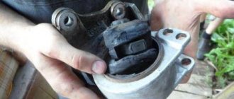
Before installing the electric lock on the rear doors, please note that you will initially need to bend the electric lock rod into the shape of the letters “V” or “Z” with your own hands, and then cut it off. There is little space available for such work, so experts recommend proceeding carefully.
The important points in this matter are the following.
- Dismantling door trim where activators are to be installed. It is recommended to have several caps in stock, as they break easily.
- Electric locks are installed taking into account the minimum load that will be placed on them during operation.
- The location of the drive rod is parallel to the standard rod. When carrying out this work on the front doors, you will need to attach the rod with the activator to its outer side, making a mark using an awl. Then 2 holes are made.
- Routing wires through rubber bushings.
- The holes in the rack and the door are made coaxial, taking into account the dimensions of the bushings. Otherwise, the hole is made using a file.